
Light Music Player
The Light Music Player is a multimedia demo project based on the Quectel Pi H1 single-board computer.
By playing local music files and performing real-time analysis of the audio signal, the project drives a 16×16 WS2812 RGB LED matrix to display lighting effects that change in sync with the music rhythm, enabling coordinated music-and-light visualization.
This project is mainly intended to demonstrate the Quectel Pi H1’s capabilities in audio processing, SPI peripheral control, and multi-threaded real-time rendering. It can serve as a reference example for applications such as music visualization, ambient lighting, and LED display solutions.
Development Resources Summary
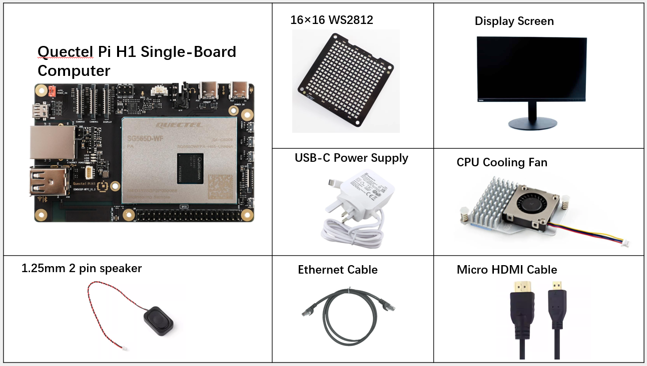
Development Accessories List
| Accessory Name | Quantity | Specifications |
|---|---|---|
| Quectel Pi H1 smart single-board computer | 1 | Quectel Pi H1 Smart Ecosystem Development Board |
| 16×16 WS2812 RGB full-color LED matrix display | 1 | 16×16 WS2812 RGB full-color LED matrix display |
| 1.25mm 2 pin speaker | 1 | 1.25mm 2 pin speaker |
| USB-C Power Supply | 1 | 27W USB Type-C Interface Charger 1.2m Cable Length Standard Power PD Power Supply Suitable for Raspberry Pi 5 |
| USB-C DP Cable / Micro HDMI Cable | 1 | DP 1.4 spec; Length: 1m; USB-C (male) to USB-C (male) Micro HDMI 2.0 spec; Length: 1m; HDMI-A (male) to HDMI-D (male) |
| Ethernet Cable | 1 | Length: 1m; Transmission Rate: Gigabit |
| CPU Cooling Fan(Optional) | 1 | Raspberry Pi 5 Official Active Cooler with Heatsink and Thermal Pad |
| Display Screen | 1 | 24-inch HDMI Monitor |
Physical Reference of Accessories
Get Started Quickly
Development Preparation
The Quectel Pi H1 comes pre-installed with Debian 13, so no re-flashing is required. Just follow the steps below.
Hardware Connection
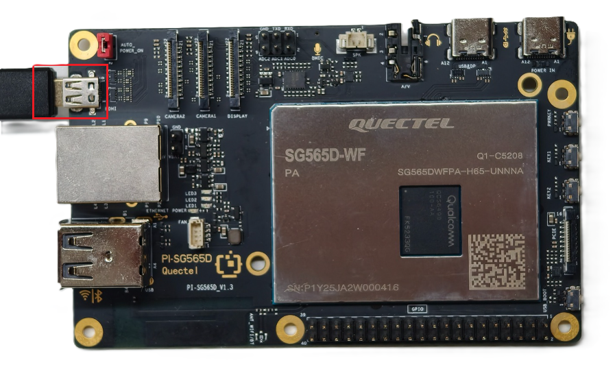
Display Connection
Connect one end of the Micro HDMI cable to the Micro HDMI port of the single-board computer and the other end to the HDMI port of the monitor.
Input Device Connection
Connect the USB keyboard and mouse to the two USB-A ports on the single-board computer. If using a wireless input device, just plug the receiver into the USB port.

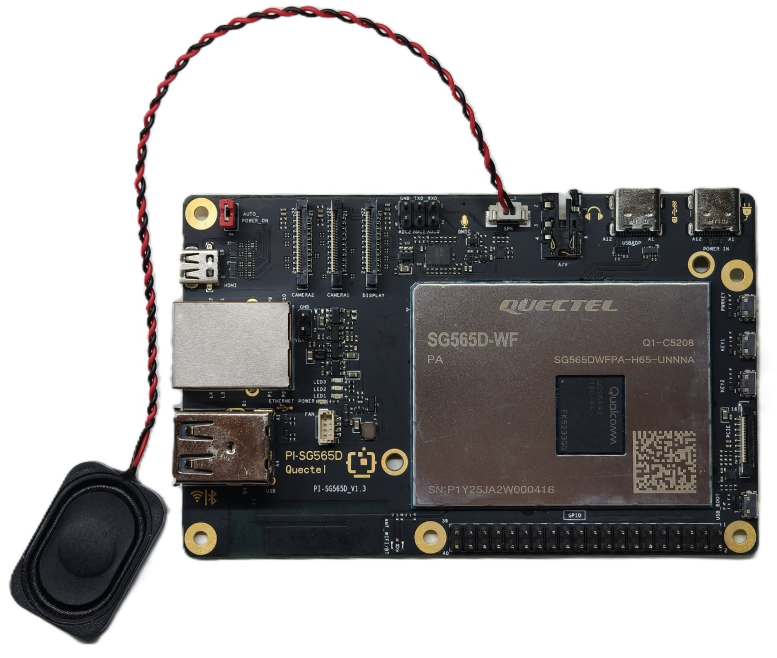
Speaker Connection
Connect the 2-pin PH1.25 speaker to the board’s speaker output.
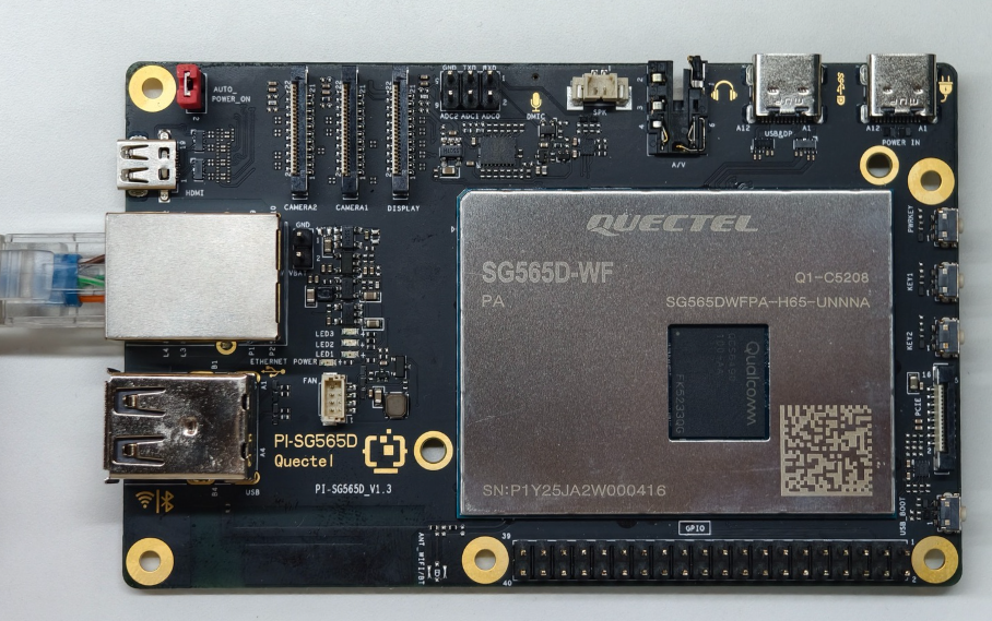
Network Connection
Connect one end of the Ethernet cable to the Gigabit Ethernet port of the single-board computer, and the other end to the Ethernet port of the router (ensure the router is already connected to the network).
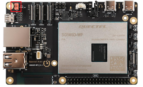
Jumper Cap Connection
Locate the pin header labeled AUTO_POWER_ON at the upper left corner of the single-board computer, and ensure it is shorted with a jumper cap.
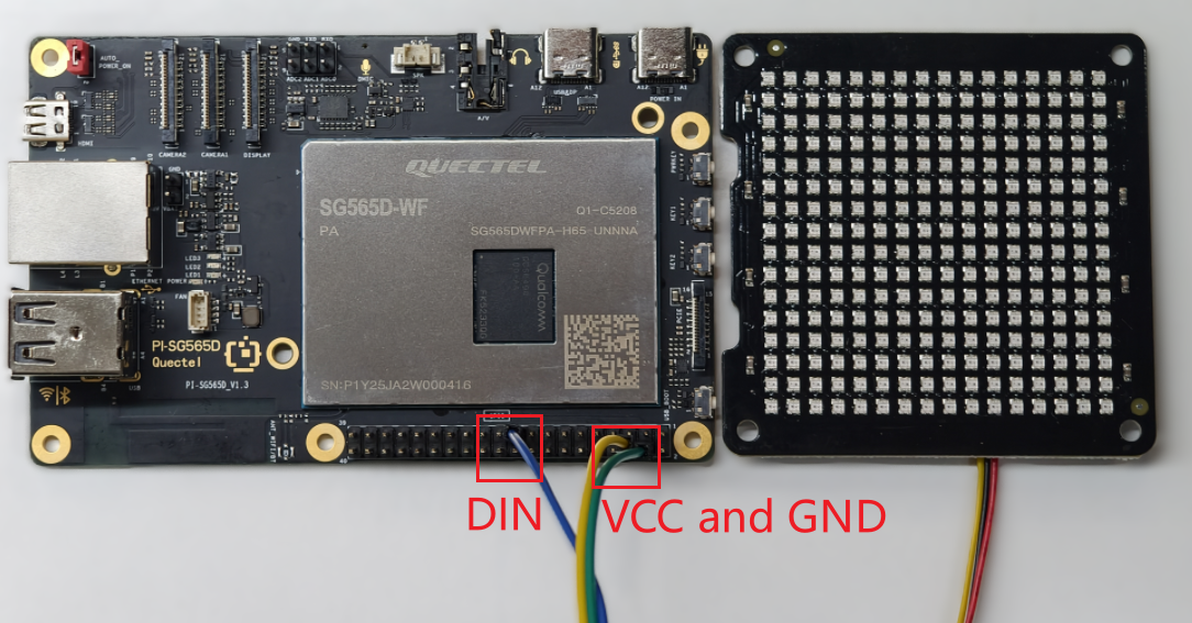
Connecting the 16×16 WS2812
The 16×16 WS2812 RGB LED matrix display is connected to the Quectel Pi H1 single-board computer via the SPI interface. Connect the WS2812 data input to the corresponding interface pin on the Quectel Pi H1.
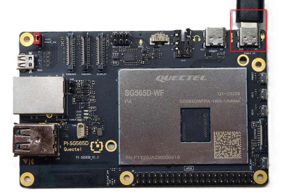
Power Connection
Connect the USB-A end of the USB-A power cable to the power supply, and connect the USB-C end to the power port of the single-board computer (usually labeled POWER IN).
Project Implementation
Prerequisites Installation
After confirming that the device is connected to the network, open a terminal and enter the following commands:
sudo apt update && sudo apt install -y pulseaudio-utils python3-numpy python3-spidev ffmpeg
The above commands will update the software sources and install several libraries required to run the project, including:
- pulseaudio-utils: Provides audio utilities such as
pacat, used to play decoded PCM audio data on the system; - python3-numpy: Used for FFT spectrum analysis and numerical computation of audio signals, supporting spectrum-based lighting effects;
- python3-spidev: Enables Python access to the SPI interface, used to drive the WS2812 RGB LED matrix;
- ffmpeg: Used to decode MP3/WAV and other audio files into a PCM data stream for audio playback and real-time analysis.
Configuring the 40-Pin Interface Configuration File
To ensure communication between the Quectel Pi H1 mainboard and the 16×16 WS2812 matrix, SPI10 on the 40-pin header must be enabled. Proceed as follows:
- On the Quectel Pi mainboard, modify the qpi-config.ini configuration file. First, run the following command to open the file:
vi /etc/qpi-config/qpi-config.ini, then update its content to:
i2c9=enable
spi10=enable
uart12_2w=enable
i2c13=enable
#need pull up gpio47 in you app when use spi14
spi14=disable
led_red_trigger=none
led_blue_trigger=none
led_green_trigger=heartbeat
led_red_brightness=0
led_blue_brightness=0
led_green_brightness=100
- In the terminal, run
sudo qpi-config 40pin set, then restart the Quectel Pi H1 mainboard for the configuration to take effect.
Obtaining the Code
Extract the code package to the device. If you are accessing the device remotely,refer to SCP File Transfer for file transfer instructions.
Preparing Music Files
Copy the music files to be played (supports MP3 / WAV formats) to the following directory:
/home/pi/Music
After the program starts, it will automatically scan this directory for music files and generate a playlist.
Application Demo
Running the Program
Run the following commands in the project directory to start the program:
cd light_music_player
sudo python3 light_music_player.py
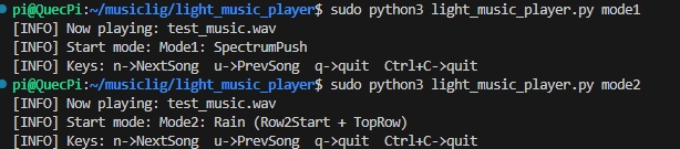
The lighting effect can be configured as mode1 or mode2. After the program starts, it will automatically begin playing music and display lighting effects synchronized to the music rhythm on the 16×16 WS2812 LED matrix.
After the program is running, the terminal will show the key controls (n for next track, u for previous track, q or Ctrl+C to exit the program).
Lighting Effect Description
Notes: 16×16 WS2812 LED Matrix Layout
Since 16×16 WS2812 RGB LED panels from different vendors may differ in their physical wiring, the panel used in this project follows the layout below:
- Starting LED position: bottom-left corner (LED 0)
- Direction of the first row: left to right (LED 0 → LED 15)
- Row progression: bottom to top
- Wiring pattern: serpentine
In other words, the first row runs from left to right, the second row returns from right to left, and so on, extending upward.
All lighting effects in the program (spectrum direction, raindrop direction, etc.) are mapped based on the above layout.
If the wiring pattern of the WS2812 panel you use does not match this description, the display direction may appear reversed or misaligned. In that case, adjust the LED matrix mapping configuration according to the actual wiring of your panel.
mode1 — Spectrum Push Effect
This mode is based on the 16-band spectrum analysis of the audio:
- Each column of the LED matrix corresponds to the energy of one frequency band;
- The bar height changes in real time with the spectrum energy;
- Supports smooth rising, slow falling, and peak-hold effects;
- When there is a sudden change in the music rhythm, the overall display produces a pronounced “pushing” visual effect.
mode2 — Raindrop Lighting Effect
This mode simulates raindrops falling from the top of the matrix:
- The raindrop generation rate changes dynamically with the music intensity;
- Supports trailing effects and background color filling;
- The louder the volume, the denser the raindrops and the higher the brightness.
Technical Support and Contributions
If you encounter any issues during use, please submit technical inquiries on the Quectel Official Forum. Our technical support team will respond promptly.
Project open-source repository: https://github.com/Quectel-Pi/demo-light-music-player
We welcome you to submit Issues to report problems or Pull Requests to contribute code improvements!