
User Guide
This document introduces the common features and usage methods of the Quectel Pi H1 smart single-board computer, including audio and multimedia, machine learning, etc..
Audio and Multimedia
PulseAudio Service
PulseAudio is a mainstream audio service system in Linux environments. It sits between applications and the underlying audio architecture (TinyALSA), responsible for managing audio streams, mixing multiple audio channels, and routing to different output devices.
PulseAudio Overview
PulseAudio is a cross-platform, network-capable sound service that accepts sound input from one or more sources (processes or input devices) and redirects sound to one or more sinks (sound cards, remote network PulseAudio services, or other processes). It interacts with the lowest-level ALSA (Advanced Linux Sound Architecture) and provides a unified interface for applications, enabling advanced features such as multi-channel audio mixing and audio forwarding.
View Sound Card Information
Enter the following command in the terminal to view the sound card mounting status:
root@qcm6490-idp:/opt# cat /proc/asound/cards
 0 [qcm6490idpsndca]: qcm6490 - qcm6490-idp-snd-card
                      qcm6490-idp-snd-card
View and Manage Device
View Available Output Devices (Sinks)
To view the currently available audio output devices and their detailed information of the system, you can use the following command. This command will list the indexes and names of all available sinks (output devices). Example output:
root@qcm6490-idp:/# pactl list short sinks
*       0       low-latency0    module-pal-card.c       s16le 1ch 16000Hz       SUSPENDED
1       deep-buffer0    module-pal-card.c       s16le 2ch 48000Hz       SUSPENDED
2       offload0        module-pal-card.c       s16le 2ch 48000Hz       SUSPENDED
3       voip-rx0        module-pal-card.c       s16le 2ch 48000Hz       SUSPENDED
The * mark indicates the current default output device.
To obtain more detailed device information, use:
root@qcm6490-idp:/# pactl list sinks
Sink #0
        State: SUSPENDED
        Name: low-latency0
        Description: pal sink to play via low-latency path
        Driver: module-pal-card.c
        Sample Specification: s16le 1ch 16000Hz
        Channel Map: mono
        Owner Module: 1
        Mute: no
        Volume: mono: 65536 / 100%
                balance 0.00
        Base Volume: 65536 / 100%
        Monitor Source: low-latency0.monitor
        Latency: 0 usec, configured 0 usec
        Flags: HARDWARE HW_VOLUME_CTRL LATENCY
        Properties:
                device.string = "low_latency"
                device.description = "pal sink to play via low-latency path"
                device.icon_name = "audio-card"
        Ports:
                speaker: speaker (type: Unknown, priority: 200, available)
                headset: headset (type: Unknown, priority: 100, available)
        Active Port: speaker
        Formats:
                pcm

Sink #1
        State: SUSPENDED
        Name: deep-buffer0
        Description: pal sink to play via deep buffer path
        Driver: module-pal-card.c
        Sample Specification: s16le 2ch 48000Hz
        Channel Map: front-left,front-right
        Owner Module: 1
        Mute: no
        Volume: front-left: 65536 / 100%,   front-right: 65536 / 100%
                balance 0.00
        Base Volume: 65536 / 100%
        Monitor Source: deep-buffer0.monitor
        Latency: 0 usec, configured 0 usec
        Flags: HARDWARE HW_VOLUME_CTRL LATENCY
        Properties:
                device.string = "deep_buffer"
                device.description = "pal sink to play via deep buffer path"
                device.icon_name = "audio-card"
        Ports:
                speaker: speaker (type: Unknown, priority: 200, available)
                headset: headset (type: Unknown, priority: 100, available)
                bta2dp-out: BT a2dp source port (type: Unknown, priority: 50, not available)
        Active Port: speaker
        Formats:
                pcm

Sink #2
        State: SUSPENDED
        Name: offload0
        Description: pal sink to play compressed via offload path
        Driver: module-pal-card.c
        Sample Specification: s16le 2ch 48000Hz
        Channel Map: front-left,front-right
        Owner Module: 1
        Mute: no
        Volume: front-left: 65536 / 100%,   front-right: 65536 / 100%
                balance 0.00
        Base Volume: 65536 / 100%
        Monitor Source: offload0.monitor
        Latency: 0 usec, configured 0 usec
        Flags: HARDWARE HW_VOLUME_CTRL LATENCY
        Properties:
                device.string = "offload"
                device.description = "pal sink to play compressed via offload path"
                device.icon_name = "audio-card"
        Ports:
                speaker: speaker (type: Unknown, priority: 200, available)
                headset: headset (type: Unknown, priority: 100, available)
                bta2dp-out: BT a2dp source port (type: Unknown, priority: 50, not available)
        Active Port: speaker
        Formats:
                mpeg
                aac

Sink #3
        State: SUSPENDED
        Name: voip-rx0
        Description: pal sink to play via voip rx path
        Driver: module-pal-card.c
        Sample Specification: s16le 2ch 48000Hz
        Channel Map: front-left,front-right
        Owner Module: 1
        Mute: no
        Volume: front-left: 65536 / 100%,   front-right: 65536 / 100%
                balance 0.00
        Base Volume: 65536 / 100%
        Monitor Source: voip-rx0.monitor
        Latency: 0 usec, configured 0 usec
        Flags: HARDWARE HW_VOLUME_CTRL LATENCY
        Properties:
                device.string = "voip_rx"
                device.description = "pal sink to play via voip rx path"
                device.icon_name = "audio-card"
        Ports:
                speaker: speaker (type: Unknown, priority: 200, available)
                headset: headset (type: Unknown, priority: 100, available)
                btsco-out: BT SCO sink port (type: Unknown, priority: 50, not available)
        Active Port: speaker
        Formats:
                pcm
View Input Devices (Sources)
Similarly, you can view audio input devices (such as microphones):
root@qcm6490-idp:/# pactl list short sources
0       low-latency0.monitor    module-pal-card.c       s16le 1ch 16000Hz       SUSPENDED
1       deep-buffer0.monitor    module-pal-card.c       s16le 2ch 48000Hz       SUSPENDED
2       offload0.monitor        module-pal-card.c       s16le 2ch 48000Hz       SUSPENDED
3       voip-rx0.monitor        module-pal-card.c       s16le 2ch 48000Hz       SUSPENDED
4       regular0        module-pal-card.c       s16le 2ch 48000Hz       SUSPENDED
5       regular2        module-pal-card.c       s16le 2ch 48000Hz       SUSPENDED
6       voip-tx0        module-pal-card.c       s16le 1ch 48000Hz       SUSPENDED
Recording
Onboard DMIC Recording
root@qcm6490-idp:~# pactl set-source-port 5 speaker-mic
root@qcm6490-idp:~# parec -d 5 --file-format=wav output.wav
3.5 mm Headphone Recording
Before using 3.5 mm headphones for recording, you need to set gpio8 and gpio68 to high level.
root@qcm6490-idp:/opt# rgpiod &
root@qcm6490-idp:/opt# sleep 1
root@qcm6490-idp:/opt# rgs c 999 go 4
root@qcm6490-idp:/opt# rgs c 999 gso 0 8
root@qcm6490-idp:/opt# rgs c 999 gw 0 8 1
root@qcm6490-idp:/opt# rgs c 999 gso 0 68
root@qcm6490-idp:/opt# rgs c 999 gw 0 68 1
- gpio8: Headphone European standard/US standard switching control. 0: European standard; 1: US standard.
- gpio68: Headphone power supply enable switch. 0: disabled; 1: enabled.
root@qcm6490-idp:~# pactl set-source-port 5 headset-mic
root@qcm6490-idp:~# parec -d 5 --file-format=wav output1.wav
Playback
Speaker Playback
GPIO controls the PA enable switch:
rgpiod &
sleep 1
rgs c 999 go 4
rgs c 999 gso 0 142
rgs c 999 gw 0 142 1
root@qcm6490-idp:~# pactl set-sink-port 0 speaker
root@qcm6490-idp:~# paplay output.wav
3.5 mm Headphone Playback
root@qcm6490-idp:~# pactl set-sink-port 0 headset
root@qcm6490-idp:~# paplay output1.wav
TinyALSA/AGM Direct Audio Link Testing
The Quectel Pi H1 smart single-board computer supports various direct audio links such as external MIC recording, 3.5 mm headphone recording and playback. The following examples demonstrate how to directly access the sound card using the TinyALSA/AGM toolchain.
View Sound Card Information
- Enter the following command in the terminal to view the sound card mounting status:
root@qcm6490-idp:/opt# cat /proc/asound/cards
 0 [qcm6490idpsndca]: qcm6490 - qcm6490-idp-snd-card
                      qcm6490-idp-snd-card
- Enter the following command in the terminal to view the list of allocated PCM streams:
root@qcm6490-idp:/opt# cat /proc/asound/pcm
00-00: CODEC_DMA-LPAIF_RXTX-RX-0 multicodec-0 :  : playback 1
00-01: CODEC_DMA-LPAIF_RXTX-TX-3 multicodec-1 :  : capture 1
00-02: CODEC_DMA-LPAIF_VA-TX-0 va_macro_tx1-2 :  : capture 1
External MIC Recording
- Stop PulseAudio to avoid occupying the audio device, and set up the capture link:
root@qcm6490-idp:/opt# systemctl stop pulseaudio
root@qcm6490-idp:/opt# tinymix set "VA DMIC MUX0" "DMIC0"
root@qcm6490-idp:/opt# tinymix set "VA_AIF1_CAP Mixer DEC0" "1"
root@qcm6490-idp:/opt# tinymix set "VA_DEC0 Volume" "100"
root@qcm6490-idp:/opt# agmcap test1.wav -D 100 -d 101 -c 1 -r 48000 -b 16 -i "CODEC_DMA-LPAIF_VA-TX-0"
-c 1: Mono recording-r 48000: 48 kHz of sample rate-b 16: 16-bit of sample bit depth-i "CODEC_DMA-LPAIF_VA-TX-0": Specify input device interface
- Press
Ctrl+Cto stop recording, and thetest1.wavfile will be generated in the current directory:
root@qcm6490-idp:/opt# ls
cni  containerd  test1.wav
3.5 mm Headphone Recording
- Set
gpio8andgpio68to high level to enable headphone standard switching and power supply:
root@qcm6490-idp:/opt# rgpiod &
root@qcm6490-idp:/opt# sleep 1
root@qcm6490-idp:/opt# rgs c 999 go 4
root@qcm6490-idp:/opt# rgs c 999 gso 0 8
root@qcm6490-idp:/opt# rgs c 999 gw 0 8 1
root@qcm6490-idp:/opt# rgs c 999 gso 0 68
root@qcm6490-idp:/opt# rgs c 999 gw 0 68 1
- Configure the recording link and start capturing:
root@qcm6490-idp:/opt# systemctl stop pulseaudio
root@qcm6490-idp:/opt# tinymix set "TX DEC0 MUX" "SWR_MIC"
root@qcm6490-idp:/opt# tinymix set "TX SMIC MUX0" "ADC1"
root@qcm6490-idp:/opt# tinymix set "TX_AIF1_CAP Mixer DEC0" "1"
root@qcm6490-idp:/opt# tinymix set "ADC2 MUX" "INP2"
root@qcm6490-idp:/opt# tinymix set "ADC2 Switch" "1"
root@qcm6490-idp:/opt# tinymix set "ADC2_MIXER Switch" "1"
root@qcm6490-idp:/opt# tinymix set "TX_DEC0 Volume" "80"
root@qcm6490-idp:/opt# tinymix set "ADC2 Volume" "20"
root@qcm6490-idp:/opt# agmcap test2.wav -D 100 -d 101 -c 1 -r 48000 -b 16 -i "CODEC_DMA-LPAIF_RXTX-TX-3"
- Press
Ctrl+Cto stop recording, and thetest2.wavfile will be generated in the current directory:
root@qcm6490-idp:/opt# ls
cni  containerd  test2.wav
3.5mm Headphone Playback
- Similarly, first pull
gpio8andgpio68to high to enable the headphone:
root@qcm6490-idp:/opt# rgpiod &
root@qcm6490-idp:/opt# sleep 1
root@qcm6490-idp:/opt# rgs c 999 go 4
root@qcm6490-idp:/opt# rgs c 999 gso 0 8
root@qcm6490-idp:/opt# rgs c 999 gw 0 8 1
root@qcm6490-idp:/opt# rgs c 999 gso 0 68
root@qcm6490-idp:/opt# rgs c 999 gw 0 68 1
- Set the playback path and use
agmplayfor audio output:
root@qcm6490-idp:/opt# systemctl stop pulseaudio
root@qcm6490-idp:/opt# tinymix set "RX_MACRO RX0 MUX" "AIF1_PB"
root@qcm6490-idp:/opt# tinymix set "RX_MACRO RX1 MUX" "AIF1_PB"
root@qcm6490-idp:/opt# tinymix set "RX INT0_1 MIX1 INP0" "RX0"
root@qcm6490-idp:/opt# tinymix set "RX INT1_1 MIX1 INP0" "RX1"
root@qcm6490-idp:/opt# tinymix set "RX INT0 DEM MUX" "CLSH_DSM_OUT"
root@qcm6490-idp:/opt# tinymix set "RX INT1 DEM MUX" "CLSH_DSM_OUT"
root@qcm6490-idp:/opt# tinymix set "RX_COMP1 Switch" "1"
root@qcm6490-idp:/opt# tinymix set "RX_COMP2 Switch" "1"
root@qcm6490-idp:/opt# tinymix set "HPHL Switch" "1"
root@qcm6490-idp:/opt# tinymix set "HPHR Switch" "1"
root@qcm6490-idp:/opt# tinymix set "HPHL_RDAC Switch" "1"
root@qcm6490-idp:/opt# tinymix set "HPHR_RDAC Switch" "1"
root@qcm6490-idp:/opt# agmplay test.wav -D 100 -d 100 -i "CODEC_DMA-LPAIF_RXTX-RX-0"
- Audio playback will automatically stop when finished. To stop early, press
Ctrl+C.
Machine Learning
NPU Application Scenarios
In the Quectel Pi H1 smart single-board computer, NPU resource application scenarios include: image classification, object detection, semantic segmentation, etc. This section takes the ResNeXt50 machine learning model in image classification as an example. The model can classify images in the Imagenet dataset and can also serve as a backbone for building more complex models for specific use cases.
Download Quantized Model
Deploy Model
Deploy the model and the label file to Quectel Pi H1, and then deploy them to the /opt directory via adb or scp.
Model characteristics:
- Model checkpoint: Imagenet
- Input resolution: 224 x 224
- Number of parameters: 88.7 M
- Model size: 87.3 MB
Connect Display
Prepare a display and connect it to Quectel Pi H1.
Run Command
Run the following command in the device terminal to ensure the results are displayed on the connected display:
export XDG_RUNTIME_DIR=/dev/socket/weston && export WAYLAND_DISPLAY=wayland-1
Run the following command on the device:
gst-launch-1.0 -e --gst-debug=2 filesrc location=/opt/video11.mp4 ! qtdemux ! queue ! h264parse ! v4l2h264dec capture-io-mode=5 output-io-mode=5 ! queue ! tee name=split split. ! queue ! qtivcomposer name=mixer sink_1::position="<30, 30>" sink_1::dimensions="<640, 360>" ! queue ! waylandsink sync=true fullscreen=true split. ! queue ! qtimlvconverter ! queue ! qtimltflite delegate=external external-delegate-path=libQnnTFLiteDelegate.so external-delegate-options="QNNExternalDelegate,backend_type=htp;" model=/opt/resnext50_quantized.tflite ! queue ! qtimlvclassification threshold=35.0 results=5 module=mobilenet labels=/opt/imagenet_labels.txt extra-operation=softmax constants="Resnetnet,q-offsets=<30.0>,q-scales=<0.06314703077077866>;" ! video/x-raw,format=BGRA,width=256,height=144 ! queue ! mixer.
Command Description
- gst-launch-1.0: This is the command-line tool of GStreamer for starting a GStreamer pipeline. The -e parameter after it means exit when the pipeline ends, rather than continuing to run.
- --gst-debug=2: Sets debug level to 2, indicating to display the debug information.
- filesrc location=/opt/video11.mp4: Specifies the input video file path.
- !: This is a connection symbol used to connect the output of the previous element to the input of the next element.
- qtdemux: Parses the input video files into multiple streams.
- queue: buffers the input data.
- h264parse: Parses input data into H.264 format data.
- v4l2h264dec: Decodes H.264 format data into YUV format.
- capture-io-mode=5: Specifies the memory access mode of the decoder input port (Capture Side).
- output-io-mode=5:Specifies the memory access mode of the decoder output port (Output Side).
- tee name=split:Splits input data into two branches.
- split.:The first branch is used to display the original video stream.
- qtivcomposer:Combines multiple video streams.
- waylandsink:Displays the combined video stream on the screen.
- split.:The second branch is used for image classification.
- qtimlvconverter:Converts the input data to model input format.
- qtimltflite:Executes model inference.
- delegate=external:Uses external acceleration library (i.e., non-TFLite default CPU backend) to run model inference,usually used to call hardware accelerators.
- external-delegate-path=libQnnTFLiteDelegate.so:Specifies the external acceleration library (Delegate) path of TensorFlow Lite.
- external-delegate-options="QNNExternalDelegate,backend_type=htp;":Specifies external acceleration library options. Here the backend type is specified as HTP (High-Throughput Processing).
- model=/opt/resnext50_quantized.tflite:Specifies model path.
- qtimlvclassification:Classifies model outputs.
- video/x-raw,format=BGRA,width=256,height=144:Specifies output video format and dimensions.
- mixer:Combines the outputs of the two branches.
- threshold=35.0:Sets confidence threshold to filter low-confidence classification results.
- results=5:Sets the number of classification results.
- module=mobilenet:Specifies the model name to use.
- labels=/opt/imagenet_labels.txt:Specifies the label file path.
- extra-operation=softmax:Performs Softmax operation on model output to get the probability of each category.
- constants="Resnetnet,q-offsets=<30.0>,q-scales=<0.06314703077077866>;":Specifies model quantization parameters.
Run Results
After running the command, the display will show the video stream and image classification results.

TensorFlow Lite Introduction
TensorFlow Lite is a set of tools that help developers run models on mobile devices, embedded devices, and edge devices to implement on-device machine learning.The following uses the posenet machine learning model for pose estimation as an example to demonstrate the real-time inference and display process.
Download posenet Model
Deploy Model
- Deploy the model and the label file to Quectel Pi H1, and then deploy them to the /opt directory via adb or scp.
- Model characteristics:
- Model checkpoint:mobilenet_v1_101
- Input resolution:513 x 257
- Number of parameters:3.31 M
- Model size:12.7 MB
Connect Camera and Display
- Prepare a MIPI camera,and connect it to the first CSI slot.
- Prepare an HDMI display,and connect it to the development board.
Use TFLite for Pose Estimation and Display
- Set Wayland environment variables:
export XDG_RUNTIME_DIR=/dev/socket/weston && export WAYLAND_DISPLAY=wayland-1
- Start real-time pose estimation:
setprop persist.overlay.use_c2d_blit 2

gst-launch-1.0 -e \
qtiqmmfsrc name=camsrc camera=0 ! video/x-raw\(memory:GBM\),format=NV12,width=1280,height=720,framerate=30/1,compression=ubwc ! queue ! tee name=split \
split. ! queue ! qtimetamux name=metamux ! queue ! qtioverlay ! queue ! waylandsink fullscreen=true sync=false \
split. ! queue ! qtimlvconverter ! queue ! qtimltflite delegate=external external-delegate-path=libQnnTFLiteDelegate.so external-delegate-options="QNNExternalDelegate,backend_type=htp;" model=/opt/posenet_mobilenet_v1.tflite ! queue ! qtimlvpose threshold=51.0 results=2 module=posenet labels=/opt/posenet_mobilenet_v1.labels constants="Posenet,q-offsets=<128.0,128.0,117.0>,q-scales=<0.0784313753247261,0.0784313753247261,1.3875764608383179>;" ! text/x-raw ! queue ! metamux.
Key Command Description
- gst-launch-1.0:Builds GStreamer pipeline,The
-eparameter after it ensures resources are released when finished. - qtiqmmfsrc:The camera source based on QMMF.
camera=0Indicates to select the first CSI interface. - tee name=split:Copies the original video stream for display and inference respectively.
- qtimlvconverter:Converts NV12 video frames into model input tensors.
- qtimltflite:Calls TensorFlow Lite + QNN delegate to accelerate model inference with HTP.
- qtimlvpose:Performs pose decoding on inference results and output human keypoints.
- qtioverlay/qtimetamux:Overlays keypoints onto video frames and output through
waylandsink.
Run Results
After running the command, the display will show the camera stream and pose estimation results. Test Example
System Configuration and Monitoring
qpi_config is a tool for configuring Quectel Pi H1 ,provides the following functions:
- Configure onboard LED operating mode and brightness;
- Configure fan interface operating mode and fan speed;
- Configure 40-pin interface operating mode;
- Query system component temperatures;
- Query system CPU, memory and storage status;
- Configure Wi-Fi.
Onboard LED Configuration
Configure Operating Mode
qpi-config led mode <blue|green|red> <heartbeat|none>
Configure Brightness
qpi-config led brightness <blue|green|red> <0-511>
Fan Configuration
Configure Fan Speed
qpi-config fan set speed <0-255>
40-Pin Interface Operating Mode Configuration
First modify the configuration file /etc/qpi-config/qpi-config.ini,then run the following command to configure:
qpi-config 40pin set
Query System Component Temperatures
qpi-config dump temperature
Query System CPU, Memory and Storage Status
qpi-config dump systemusage
Configure Wi-Fi
Scan Wi-Fi
qpi-config wifi scan
View Existing Wi-Fi Connections
qpi-config wifi show
View Wi-Fi Connection Status
qpi-config wifi dump <connection uuid>
Add Wi-Fi Connection
qpi-config wifi connect <ssid> <password>
Delete Wi-Fi Connection
qpi-config wifi delete <connection uuid>
40PIN and Interface Expansion
The configuration file for 40PIN low-speed interfaces (i2c9/spi10/uart12_2w/i2c13/spi14) is located at /etc/qpi-config/qpi-config.ini. The configuration steps are:
- Modify the qpi-config.ini configuration
- Apply the configuration
qpi-config 40pin set
- Restart to take effect
GPIO Testing
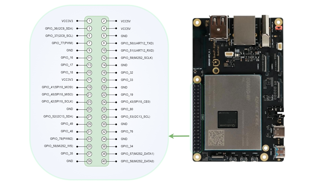
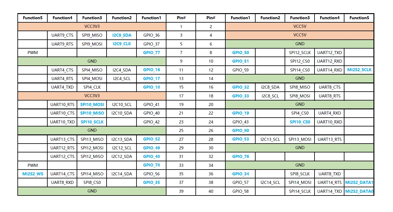
Select a 40-pin GPIO pin to test GPIO functionality. For example, select Pin3 of 40-pin for testing. Pin3 corresponds to gpio_num 36. The gpio_num information corresponding to each pin can be found in the pin mapping table.
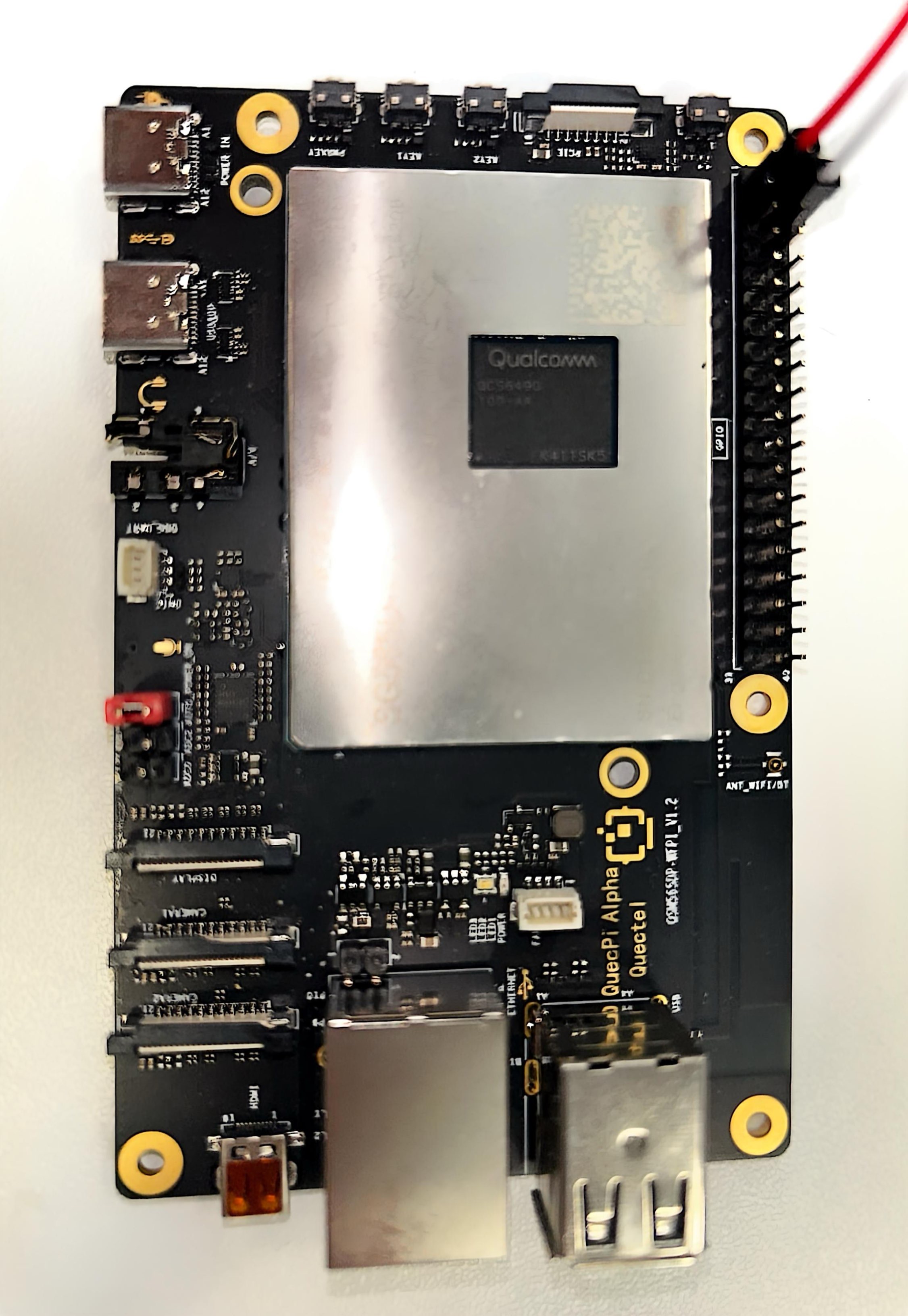
Connection diagram,where the red wire connects to the multimeter positive terminal and the white wire connects to the multimeter negative terminal:
Control Using SHELL Commands
The system has lgpiod service enabled by default. Execute the following commands in sequence to test the GPIO functionality of Pin3 of 40-pin:
rgs c 999 go 4#Use go to open /dev/gpiochip4.rgs c 999 gso 0 36#Use gso to set gpio 36 as output mode. In this command, 0 is the return value of the previous command, which shoule be modified according to actual situation.rgs c 999 gw 0 36 0#Set GPIO36 to low level. At this time, the pin voltage value is 0 V.rgs c 999 gw 0 36 1#Set GPIO36 to high level. At this time, the pin voltage value is 3.3 V.
Control Using C Code
Create a gpio.c filewith the following content:
#include <stdlib.h>
#include <lgpio.h>

int main(int argc, char **argv)
{
    int gpio_num = atoi(argv[1]);
    int pin_level = atoi(argv[2]);
    int handle = lgGpiochipOpen(4);

    lgGpioClaimOutput(handle, 0, gpio_num, 0);
    lgGpioWrite(handle, gpio_num, pin_level);
}
Compile: gcc -o gpio gpio.c -llgpio
Execute: ./gpio 36 0 #Set GPIO36 to low level. At this time, the pin voltage value is 0 V.
Execute: ./gpio 36 1 #Set GPIO36 to high level. At this time, the pin voltage value is 3.3 V.
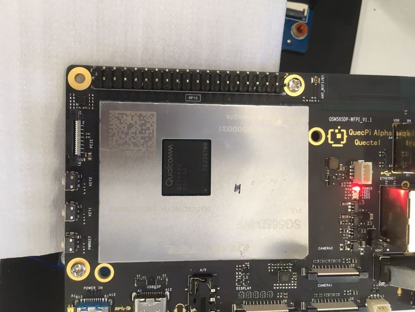
I2C Testing
40PIN's pin3 and pin5 default to I2C data and clock pins, corresponding to device node /dev/i2c9. If the node does not appear, you can first use qpi-config from the beginning of this chapter to configure and enable it.
Testing I2C interface requires an external I2C device,Here we choose the Waveshare environmental sensor expansion board,connected via 40pin interface。
Connection diagram:
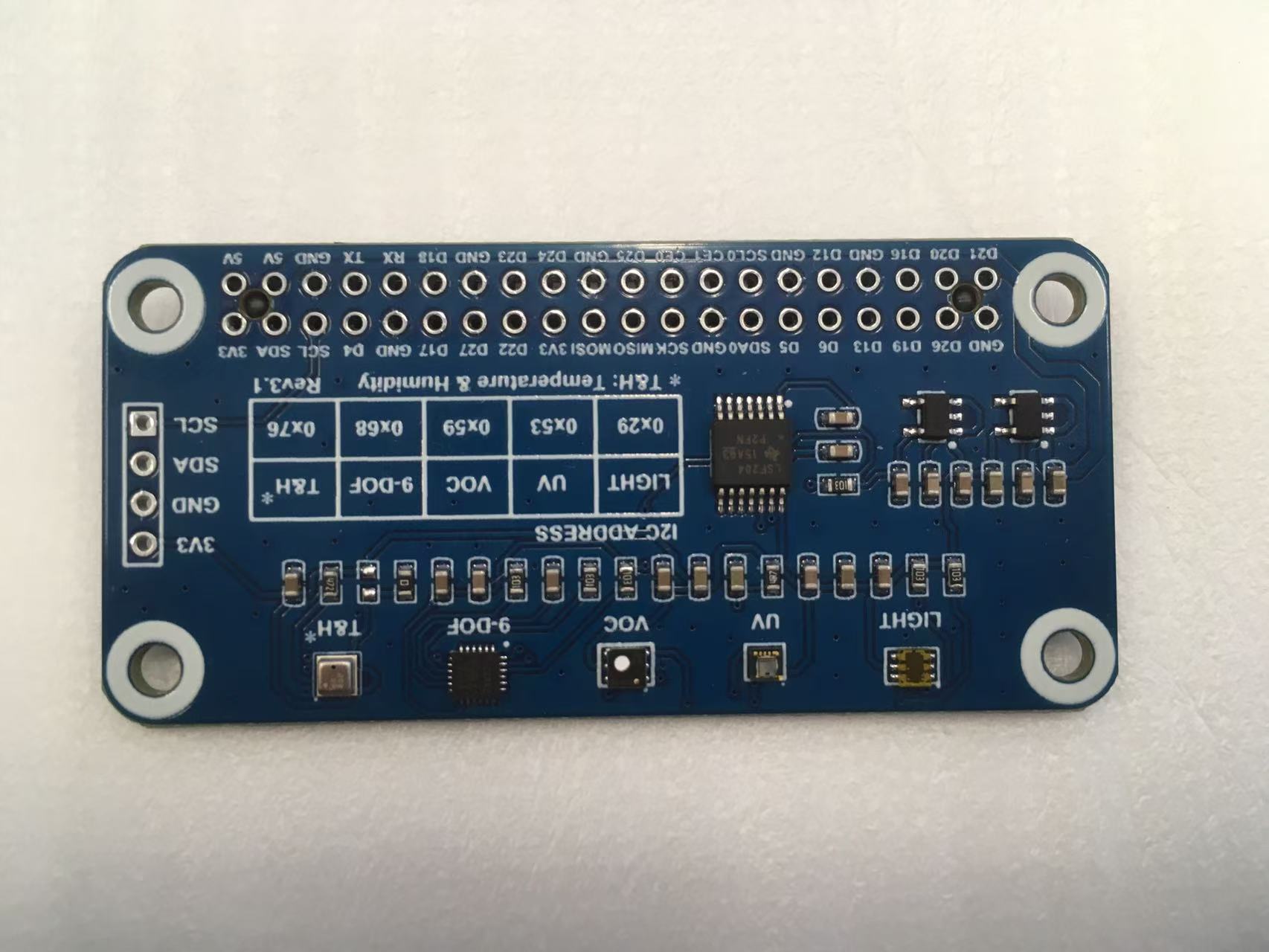
Waveshare Environmental Sensor Expansion Board
QuecTel Pi H1 40PIN Pins
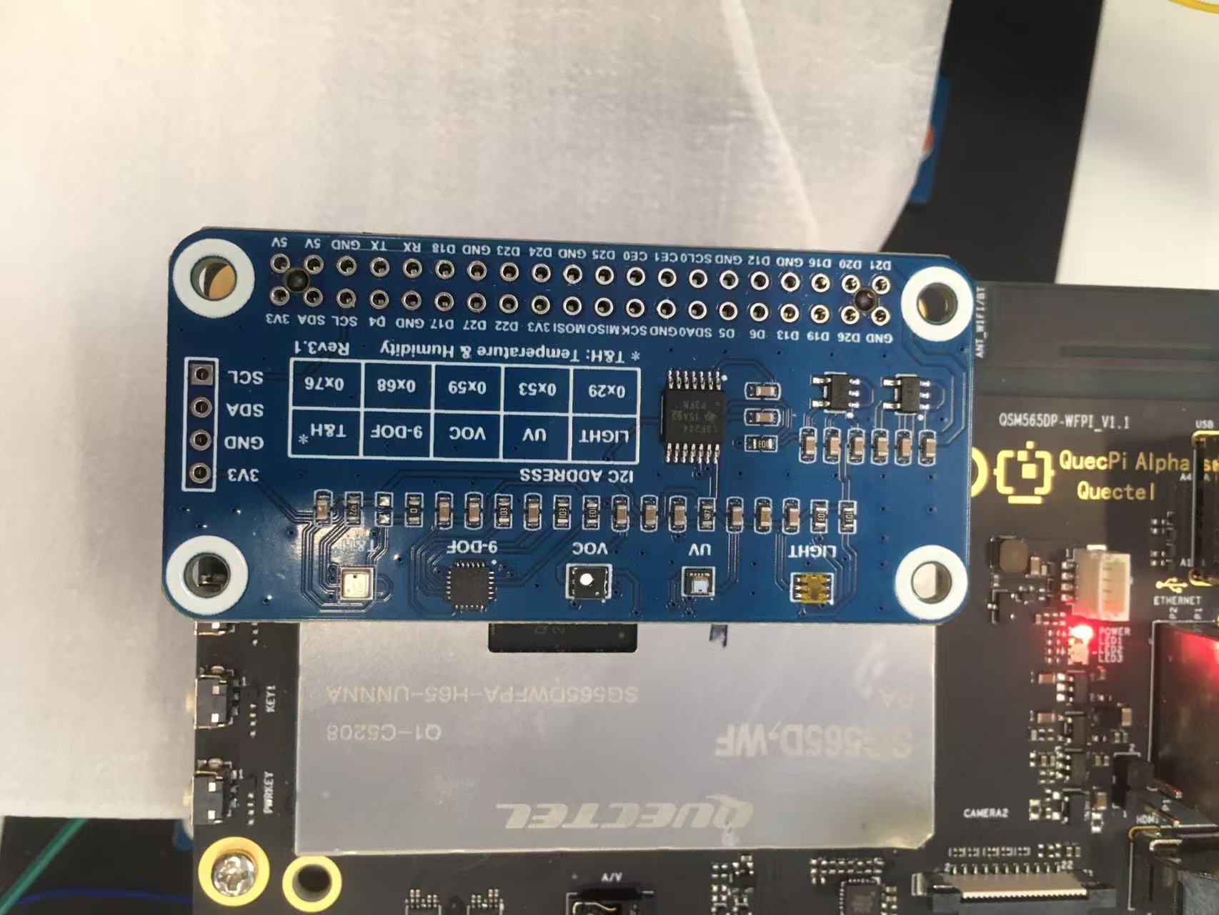
Quectel Pi H1 with Environmental Sensor Expansion Board
Test Using C Code
Test steps:
Create a new envtest.c file,with the following content:
#include <stdio.h>
#include <lgpio.h>

#define I2C_DEV_NUM 9
#define BME280_ADDR 0x76

int32_t digT[3],digP[9],digH[6];
int32_t t_fine = 0.0;

double compensate_P(int32_t adc_P)
{
    double pressure = 0.0;
    double v1,v2;
    v1 = (t_fine / 2.0) - 64000.0;
    v2 = (((v1 / 4.0) * (v1 / 4.0)) / 2048) * digP[5];
    v2 = v2 + ((v1 * digP[4]) * 2.0);
    v2 = (v2 / 4.0) + (digP[3] * 65536.0);
    v1 = (((digP[2] * (((v1 / 4.0) * (v1 / 4.0)) / 8192)) / 8)  + ((digP[1] * v1) / 2.0)) / 262144;
    v1 = ((32768 + v1) * digP[0]) / 32768;
    if(v1 == 0)
        return 0;
    pressure = ((1048576 - adc_P) - (v2 / 4096)) * 3125;
    if (pressure < 0x80000000)
        pressure = (pressure * 2.0) / v1;
    else
        pressure = (pressure / v1) * 2;
    v1 = (digP[8] * (((pressure / 8.0) * (pressure / 8.0)) / 8192.0)) / 4096;
    v2 = ((pressure / 4.0) * digP[7]) / 8192.0;
    pressure = pressure + ((v1 + v2 + digP[6]) / 16.0) ;
    return (pressure/100);
}

double compensate_T(int32_t adc_T)
{
    double temperature = 0.0;
    double v1,v2;
    v1 = (adc_T / 16384.0 - digT[0] / 1024.0) * digT[1];
    v2 = (adc_T / 131072.0 - digT[0] / 8192.0) * (adc_T / 131072.0 - digT[0] / 8192.0) * digT[2];
    t_fine = v1 + v2;
    temperature = t_fine / 5120.0;
    return temperature;
}

double compensate_H(int32_t adc_H)
{
    double var_h = t_fine - 76800.0;
    if (var_h == 0)
        return 0;
    var_h = (adc_H - (digH[3] * 64.0 + digH[4]/16384.0 * var_h)) *
        (digH[1] / 65536.0 * (1.0 + digH[5] / 67108864.0 * var_h * (1.0 + digH[2] / 67108864.0 * var_h)));
    var_h = var_h * (1.0 - digH[0] * var_h / 524288.0);
    if (var_h > 100.0)
        var_h = 100.0;
    else if (var_h < 0.0)
        var_h = 0.0;
    return var_h;
}

void get_calib_param(int handle)
{
    uint8_t calib[32];
    for(int i=0;i<24;i++) {
        calib[i] = lgI2cReadByteData(handle, 0x88 + i);
    }
    calib[24] = lgI2cReadByteData(handle, 0xA1);
    for(int i=25,o=0;i<32;i++,o++) {
        calib[i] = lgI2cReadByteData(handle, 0xE1 + o);
    }
    digT[0] = (calib[1] << 8) | calib[0];
    digT[1] = (calib[3] << 8) | calib[2];
    digT[2] = (calib[5] << 8) | calib[4];
    digP[0] = (calib[7] << 8) | calib[6];
    digP[1] = (calib[9] << 8) | calib[8];
    digP[2] = (calib[11] << 8) | calib[10];
    digP[3] = (calib[13] << 8) | calib[12];
    digP[4] = (calib[15] << 8) | calib[14];
    digP[5] = (calib[17] << 8) | calib[16];
    digP[6] = (calib[19] << 8) | calib[18];
    digP[7] = (calib[21] << 8) | calib[20];
    digP[8] = (calib[23] << 8) | calib[22];
    digH[0] = calib[24];
    digH[1] = (calib[26] << 8) | calib[25];
    digH[2] = calib[27];
    digH[3] = (calib[28] << 4) | (0x0f & calib[29]);
    digH[4] = (calib[30] << 4) | ((calib[29] >> 4) & 0x0f);
    digH[5] = calib[31];
    for(int i=1;i<2;i++)
        if((digT[i] & 0x8000) != 0) digT[i] = (-digT[i] ^ 0xFFFF) + 1;
    for(int i=1;i<8;i++)
        if ((digP[i] & 0x8000) != 0)    digP[i]=(-digP[i] ^ 0xFFFF) + 1 ;
    for(int i=0;i<6;i++)
        if ((digH[i] & 0x8000) != 0) digH[i] = (-digH[i] ^ 0xFFFF) + 1;
}

int main(int argc, char **argv)
{
    uint8_t data[8];
    double value[3];
    int handle = lgI2cOpen(I2C_DEV_NUM, BME280_ADDR, 0);

    lgI2cWriteByteData(handle, 0xF2, 0x01);
    lgI2cWriteByteData(handle, 0xF4, 0x27);
    lgI2cWriteByteData(handle, 0xF5, 0xA0);
    get_calib_param(handle);

    for(int i=0;i<8;i++) {
        data[i] = lgI2cReadByteData(handle, 0xF7 + i);
    }
    value[0] = (data[0] << 12) | (data[1] << 4) | (data[2] >> 4);
    value[1] = (data[3] << 12) | (data[4] << 4) | (data[5] >> 4);
    value[2] = (data[6] << 8)  |  data[7];
    value[0] = compensate_P(value[0]);
    value[1] = compensate_T(value[1]);
    value[2] = compensate_H(value[2]);

    printf("pressure:    %7.2f hPa\n", value[0]);
    printf("temperature: %7.2f C\n"  , value[1]);
    printf("humidity:    %7.2f %\n"  , value[2]);
    lgI2cClose(handle);
}
Compile: gcc -o envtest envtest.c -llgpio
Run: ./envtest #Output content includes collected pressure, temperature and humidity information
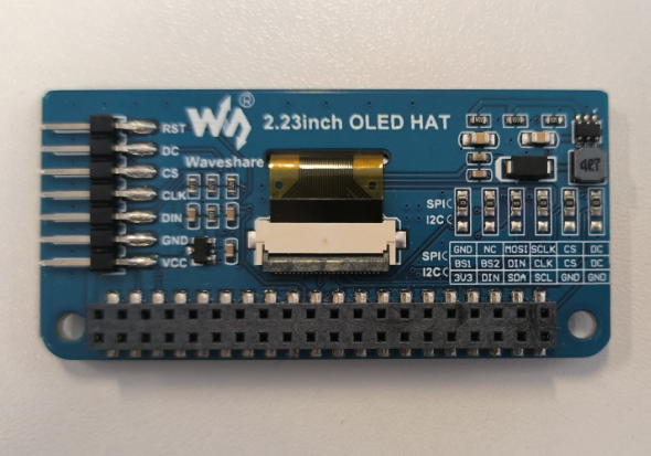
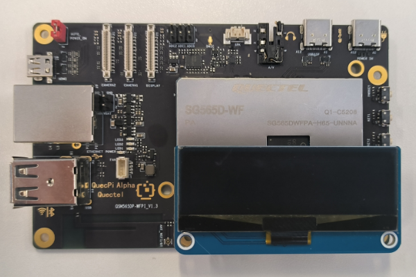
SPI Testing
Use Waveshare 2.23 inch OLED displaytest SPI functionality in 40pin,corresponding device node /dev/spi10,If the node does not appear, you can first usefrom the beginning of this chapter qpi-config to configure and enable。
Connection diagram:
Waveshare Environmental Sensor Expansion Board
Quectel Pi H1 40PIN Pins
Test steps:
wget https://www.waveshare.net/w/upload/c/c5/2.23inch-OLED-HAT-Code.7z #Download the source code provided by Waveshare
7z x 2.23inch-OLED-HAT-Code.7z #Extract the source code
cd 2.23inch-OLED-HAT-Code/Without\ scrolling/Raspberry\ Pi/SPI/c #Switch to the source code directory
Modify the source code according to the following patch content:
diff -r -u "2.23inch-OLED-HAT-Code/Without scrolling/Raspberry Pi/c/examples/main.c" quectelpi/c/examples/main.c
--- "2.23inch-OLED-HAT-Code/Without scrolling/Raspberry Pi/c/examples/main.c"	2023-12-20 03:19:38.000000000 +0000
+++ quectelpi/c/examples/main.c	2025-08-15 07:34:39.959415415 +0000
@@ -17,10 +17,13 @@
     char value[10]={'0', '1', '2', '3', '4', '5', '6', '7', '8', '9'};
     time_t now;
     struct tm *timenow;
-
-    if(DEV_ModuleInit() != 0) {
-		return -1;
-	}
+    extern int GPIO_Handle;
+    extern int SPI_Handle;
+    GPIO_Handle = lgGpiochipOpen(4); if (GPIO_Handle < 0) { printf( "gpiochip4 Export Failed\n"); return -1; }
+    lgGpioClaimOutput(GPIO_Handle, 0, 119     , LG_LOW); //enable OLED_DC mode
+    lgGpioClaimOutput(GPIO_Handle, 0, OLED_RST, LG_LOW);
+    lgGpioClaimOutput(GPIO_Handle, 0, OLED_DC , LG_LOW);
+    SPI_Handle = lgSpiOpen(10, 0, 10000000, 0);
     SSD1305_begin();
     SSD1305_bitmap(7, 0, waveshare_ch,112,32);
     SSD1305_display();
Only in quectelpi/c/lib/Config: .DEV_Config.h.un~
diff -r -u "2.23inch-OLED-HAT-Code/Without scrolling/Raspberry Pi/c/lib/Config/DEV_Config.h" quectelpi/c/lib/Config/DEV_Config.h
--- "2.23inch-OLED-HAT-Code/Without scrolling/Raspberry Pi/c/lib/Config/DEV_Config.h"	2023-12-20 03:23:11.000000000 +0000
+++ quectelpi/c/lib/Config/DEV_Config.h	2025-08-15 07:32:05.844626084 +0000
@@ -41,8 +41,8 @@

 //OLED Define
 #define OLED_CS         8
-#define OLED_RST        25
-#define OLED_DC         24
+#define OLED_RST        19
+#define OLED_DC         33
Compile: make
Run: ./main
The running effect is shown in the figure below:
UART Testing
40PIN's pin8 and pin10 are default configured as uart functionality, corresponding to device node /dev/ttyHS2. If the node does not appear, you can first use qpi-config from the beginning of this chapter to configure and enable it.
Connect the computer's USB to serial port rx to pin8, tx to pin10。
Connection diagram: 
Control Using C Code
Create a uart.c file with the following content:
#include <stdio.h>
#include <string.h>
#include <lgpio.h>

int strip_head_and_tail(char *data, int data_len)
{
    int found_tail = 0;
    if (data_len > 0 && data[0] == '\r') {
        bcopy(data + 1, data, data_len-1);
        data_len--;
    }
    if (data_len > 0 && data[0] == '\n') {
        bcopy(data + 1, data, data_len-1);
        data_len--;
    }
    if (data_len > 0 && data[data_len - 1] == '\r') {
        data_len--;
        data[data_len] = 0;
        found_tail = 1;
    }
    if (data_len > 0 && data[data_len - 1] == '\n') {
        data_len--;
        data[data_len] = 0;
        found_tail = 1;
    }
    return found_tail;
}

int main(int argc, char **argv)
{
    int handle = lgSerialOpen("/dev/ttyHS2", 115200, 0);
    char data[512];
    int data_len = 0;
    for (;;) {
        int read_len = lgSerialRead(handle,
            data + data_len, sizeof(data) - data_len);
        if (read_len > 0) {
            data_len += read_len;
        }
        if (strip_head_and_tail(data, data_len)) {
            printf("received: %s\n", data);
            lgSerialWrite(handle, "Received.\r\n", 11);
        }
        lguSleep(100);
    }
    lgSerialClose(handle);
}
Compile: gcc -o uart uart.c -llgpio
Run: ./uart #At this time, the USB-to-serial-port module is connected to the PC. Use putty or other software that supports serial communication to communicate with the serial port server program. You can input content and end with Enter key in the client(such as putty). The server program will print the user input content and return "Received." to the client.
Control Using Python Script
Create server program uart.py file with the following content:
import serial
import threading

PORT = '/dev/ttyHS2'
BAUDRATE = 115200
TIMEOUT = 1

ser = serial.Serial(PORT, BAUDRATE, timeout=TIMEOUT)

def read_and_echo(ser):
    while True:
        data = ser.readline()
        if data:
            print(f"Received: {data.decode().strip()}")
            ser.write(“Received.\r\n”)

def main():
    if ser.is_open:
        print(f"Serial port {PORT} is open. Echo service started.")
        thread = threading.Thread(target=read_and_echo, args=(ser,))
        thread.daemon = True
        thread.start()

        try:
            while True:
                pass
        except KeyboardInterrupt:
            print("Exiting program.")
    else:
        print(f"Failed to open serial port {PORT}.")

    ser.close()
    print(f"Serial port {PORT} is closed.")

if __name__ == "__main__":
    main()
Run: python uart.py #At this time, the USB-to-serial-port module is connected to PC. Use putty or other software that supports serial communication to communicate with the serial port server program. You can input content and end with Enter in the client (such as putty). The server program will print the input content and return "Received." to the client.
PWM Testing
Pin33 of 40-pin is default configured as PWM functionality. Here we choose Waveshare's 4-pin PWM protocol speed control fan as the test device.
Control Using C Code
Create a pwm.c file with the following content:
#include <stdio.h>
#include <lgpio.h>
int main(int argc, char **argv)
{
      int h;
      int gpio = 78;
      float pwmFrequency = 1000;
      float pwmDutyCycle = 50;

      h = lgGpiochipOpen(4);
      if (h < 0) {
          printf("ERROR: %s (%d)\n", lguErrorText(h), h);
          return 1;
      }

      int e = lgGpioClaimOutput(h, 0, gpio, 0);
      if (e < 0) {
          printf("ERROR: %s (%d)\n", lguErrorText(e), e);
          return 1;
      }

      e = lgTxPwm(h, gpio, pwmFrequency, pwmDutyCycle, 0, 0);
      if (e < 0) {
          printf("ERROR: %s (%d)\n", lguErrorText(e), e);
          return 1;
      }

      lguSleep(5);
      lgGpioFree(h, gpio);
      lgGpiochipClose(h);
      return 0;
}
Compile: gcc pwm.c -o pwm -llgpio
Run: ./pwm #The fan will run at medium speed,You can modify the pwmDutyCycle value in the code to adjust fan speed.
Network and Communication
Bluetooth Testing
Quectel Pi H1 smart single-board computer supports QCA1023 HCI UART Bluetooth module, and it can connect to common Bluetooth peripherals. The following process shows how to pair with keyboard and mouse.
Bluetooth Module Startup
The Bluetooth module is worked with HCI UART connecting to the main controller, and communicates via HCI H4 protocol。
First, power on the peripheral through the device node with the following command. If the command changes to echo 0, it means to power off the the Bluetooth peripheral.
echo 1 > /sys/devices/platform/rfkill/bt_en
Initialize the Bluetooth module via serial port using the hciattach command。
hciattach /dev/ttyHS1 qca 3000000 flow
Query and enable the HCI Bluetooth device using the hciconfig command。
hciconfig hci0 up
Query HCI device status via hciconfig. When the status is UP RUNNING,it means the HCI Bluetooth device has been enabled。
root@qcm6490-idp:~# hciconfig
hci0:	Type: Primary  Bus: UART
    BD Address: 00:00:00:00:5A:AD  ACL MTU: 1024:7  SCO MTU: 60:8
    UP RUNNING
    RX bytes:783665 acl:1106 sco:0 events:18678 errors:0
    TX bytes:4072 acl:57 sco:0 commands:305 errors:0
Connect Bluetooth Peripheral
Enter the Bluetooth configuration tool with bluetoothctl. If the command prompt is [bluetooth]#,it indicates that the Bluetooth control mode has been entered.
root@qcm6490-idp:~# bluetoothctl
[bluetooth]#
Execute scan on to scan the Bluetooth devices, then the surrounding Bluetooth device information will be listed. At this time, you need to turn on the pairing mode of the Bluetooth device, and place it nearby。
[bluetooth]# scan on
After scanning devices for a certain period of time,you can execute scan off to stop scanning。
[bluetooth]# scan off
Execute devices to list the scanned devices. Find your Bluetooth peripheral(here we use a Bluetooth mouse as an example).
[bluetooth]# devices
Device C3:3E:68:5E:E7:1F MX Master 2S
Use the pair command to connect,and the address is your peripheral address.
[bluetooth]# pair C3:3E:68:5E:E7:1F
When the CHG log is output,it means pairing is successful. At this time, you can find that the mouse is registered under the input device. Here the mouse is input5(Please refer to the actual registration address).
[CHG] Device C3:3E:68:5E:E7:1F Modalias: usb:v046DpB019d0006
[MX Master 2S]# [ 1157.381232][ T1737] input: MX Master 2S Keyboard as /devices/virtual/misc/uhid/0005:046D:B019.0001/input/input4
[ 1157.392409][ T1737] input: MX Master 2S Mouse as /devices/virtual/misc/uhid/0005:046D:B019.0001/input/input5
Add the device as trust and connect (Optional: If the device automatically connects, you can skip this).
[MX Master 2S]# trust C3:3E:68:5E:E7:1F
Changing C3:3E:68:5E:E7:1F trust succeeded
[MX Master 2S]# connect C3:3E:68:5E:E7:1F
Attempting to connect to C3:3E:68:5E:E7:1F
Connection successful
Verify Peripheral
At this time, we can use the evtest tool to verify whether the peripheral is available. Enter evtest to display available event devices. Then, select the correponding number 5 of the mouse.
root@qcm6490-idp:~# evtest
No device specified, trying to scan all of /dev/input/event*
Available devices:
/dev/input/event0:	pm8xxx_vib_ffmemless
/dev/input/event1:	gpio-keys
/dev/input/event2:	pmic_pwrkey
/dev/input/event3:	pmic_resin
/dev/input/event4:	MX Master 2S Keyboard
/dev/input/event5:	MX Master 2S Mouse
Select the device event number [0-5]:
When the following log appears, it means the mouse is connected successfully. You can test whether events are reported by moving the mouse and pressing the buttons.
Input driver version is 1.0.1
Input device ID: bus 0x5 vendor 0x46d product 0xb019 version 0x6
Input device name: "MX Master 2S Mouse"
Supported events:
  Event type 0 (EV_SYN)
  Event type 1 (EV_KEY)
    Event code 272 (BTN_LEFT)
    Event code 273 (BTN_RIGHT)
    Event code 274 (BTN_MIDDLE)
    Event code 275 (BTN_SIDE)
    Event code 276 (BTN_EXTRA)
    Event code 277 (BTN_FORWARD)
    Event code 278 (BTN_BACK)
    Event code 279 (BTN_TASK)
    Event code 280 (?)
    Event code 281 (?)
    Event code 282 (?)
    Event code 283 (?)
    Event code 284 (?)
    Event code 285 (?)
    Event code 286 (?)
    Event code 287 (?)
  Event type 2 (EV_REL)
    Event code 0 (REL_X)
    Event code 1 (REL_Y)
    Event code 6 (REL_HWHEEL)
    Event code 8 (REL_WHEEL)
    Event code 11 (REL_WHEEL_HI_RES)
    Event code 12 (REL_HWHEEL_HI_RES)
  Event type 4 (EV_MSC)
    Event code 4 (MSC_SCAN)
Properties:
Testing ... (interrupt to exit)
Event: time 2618.445029, type 4 (EV_MSC), code 4 (MSC_SCAN), value 90001
Event: time 2618.445029, type 1 (EV_KEY), code 272 (BTN_LEFT), value 1
Event: time 2618.445029, -------------- SYN_REPORT ------------
Event: time 2618.610162, type 4 (EV_MSC), code 4 (MSC_SCAN), value 90001
Event: time 2618.610162, type 1 (EV_KEY), code 272 (BTN_LEFT), value 0
Event: time 2618.610162, -------------- SYN_REPORT ------------
Wired Network (eth0)
Quectel Pi H1 smart single-board computer supports 1 auto-adaptive gigabit Ethernet. Ethernet cable requirements: Only supports straight-through cables, does not support crossover cables.
Network Configuration
The system enables NetworkManager service by default to manage the network.
View Network Configuration
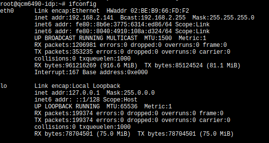
Use ifconfig to view network interface addresses:
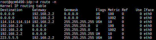
Use route -n to view network routing information,which contains default gateway address information:
Check DNS server address by viewing the /etc/resolv.conf file content:

Automatically Obtain Network Configuration
[If you are remotely connected to the device via network to modify network settings, there is a risk of losing network connection. Please ensure you have a method (such as through debug UART or display) to view the modified network configuration]
The system is set to automatically obtain network configuration by default. Connect the device to the local area network using a network cable,then the device will automatically obtain network configuration (The prerequisite is that there is an available DHCP service in the local area network).
Troubleshooting:
- View connection information:Execute
nmcli cto observe that whether the DEVICE column contains eth0 in the output results. If yes, delete it first and then recreate a connection.

- Delete old connection information:Execute
nmcli c del 'Wired connection 1'#Here 'Wired connection 1' is the connection name queried from the previous step NAME. [After deletion, a connection will be automatically created by default with NAME as eth0. At this time, network configuration will be automatically obtained.]

- Create another connection and enable it:Execute
nmcli c add type ethernet con-name eth0 ifname eth0to create a connection. Here the connection name is specified as eth0,and the network interface used is also eth0. Then executenmcli connection up eth0to make the connection named eth0 take effect. [Generally after deleting the old connection in the previous step, a connection will be automatically created with NAME as eth0 connection. At this time, network configuration will be automatically obtained. If in some cases the new connection is not automatically created, you can follow this step to create and enable a new connection]

Manually Configure Network
[If you are remotely connected to the device via network to modify network settings, there is a risk of losing network connection. Please ensure you have a method (such as through debug UART or display) to view the modified network configuration]
- View connection information:Execute
nmcli cto observe that whether the in DEVICE column contains eth0 in the output results. If yes, note its NAME value, which will be needed later. If not, first create an eth0 connection by executingnmcli c add type ethernet con-name 'Wired connection 1' ifname eth0.
- Manually configure network by executing the following command:
After modification is complete, executenmcli c modify 'Wired connection 1' \ ipv4.addresses 192.168.1.100/24 \ ipv4.gateway 192.168.1.1 \ ipv4.dns 192.168.1.1 \ ipv4.method manualnmcli c up 'Wired connection 1'to enable the connection. [In the example above, IP address, gateway address, and DNS address should be modified according to actual needs].
Test Network
Execute the ping command to test network connection:
- Execute
ping 192.168.1.1. If ping succeeds, it means the local area network connection is normal. [Here the IP address needs to be modified to the actual network gateway address]. - Execute
ping 114.114.114.114. if ping succeeds, it means the external network connection is normal。 - Execute
ping google.com. If ping succeeds, it means the external network connection is normal and DNS resolution is functioning properly.
WiFi Network Testing
Use nmcli to quickly connect Wi‑Fi:
- Check Wi‑Fi device status:
nmcli dev status - Turn on Wi‑Fi radio:
nmcli radio wifi on - Scan hotspots (specify Wi‑Fi device):
nmcli dev wifi list ifname wlan0 - Connect to hotspot:
nmcli dev wifi connect "wifi-name" password "wifi-password"
After running the connect command, seeing successfully activated indicates the network is connected.
PCIe 5G Module Connection
The Quectel Pi H1 smart single-board computer can connect to a 5G network card via PCIe interface through a riser card. This chapter introduces how to use a PCIe riser card to connect RM520N-GL PCIe network card.
PCIe Module Configuration
To use the PCIe riser card, the 5G module needs to be set to PCIe-EP mode so that it can communicate with the PCIe interface of Quectel Pi H1. After installing the 5G module driver, connect Quectel Pi H1 to the 5G module through the riser card's USB port, and input AT command to switch it to PCIe-EP mode.
- Use a Type-C to USB cable to connect to a Windows computer (At this time you may need to install the driver. The driver file is provided by Quectel technical support. Please select the appropriate driver file for installation according to the corresponding 5G module).
- Use the serial port tool to open the module AT port.
You can view the port in Device Manager of the host. The port is "Quectel USB AT Port(COM***)".
AT+QCFG="data_interface",1,0
AT+QCFG="pcie/mode",0
AT+QCFG="usbnet",2
AT+CFUN=1,1
After executing the command, unplug the PC USB port. After re-powering Quectel PI H1, use the following command through the shell port to determine if the device is properly recognized and connected.
root@qcm6490-idp:~# lspci
0000:00:00.0 PCI bridge: Qualcomm Device 010b
0000:01:00.0 Ethernet controller: Device 1f0a:6801 (rev 01)
0001:00:00.0 PCI bridge: Qualcomm Device 010b
0001:01:00.0 Unassigned class [ff00]: Qualcomm Device 0308
root@qcm6490-idp:~# ls /dev/mhi*
/dev/mhi_BHI  /dev/mhi_DIAG  /dev/mhi_DUN  /dev/mhi_LOOPBACK  /dev/mhi_QMI0
If all the above devices are recognized, then dialing can be performed normally.
Dial-up and Network Registration
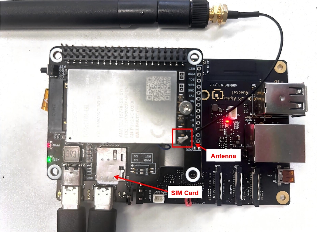
Use the quectel-CM tool for dial-up. First connect the antenna to the 5G module and insert a SIM card to avoid poor signal and inability to register to the network.
After confirming everything is correct, directly run the quectel-CM command in the background for dialing.
root@qcm6490-idp:~# quectel-CM &
[2] 1303
root@qcm6490-idp:~# [01-01_00:07:55:168] QConnectManager_Linux_V1.6.7
[01-01_00:07:55:179] network interface '' or qmidev '' is not exist
[01-01_00:07:55:179] netcard driver = pcie_mhi, driver version = V1.3.7
[01-01_00:07:55:179] qmap_mode = 1, qmap_version = 9, qmap_size = 15360, muxid = 0x81, qmap_netcard = rmnet_mhi0.1
[01-01_00:07:55:179] Modem works in QMI mode
[01-01_00:07:55:193] /proc/1273/fd/7 -> /dev/mhi_QMI0
[01-01_00:07:55:193] /proc/1273/exe -> /usr/bin/quectel-CM
[01-01_00:07:55:193] requestDeactivateDefaultPDP WdsConnectionIPv4Handle
[01-01_00:07:55:424] ip link set dev rmnet_mhi0 down
[01-01_00:07:55:431] ip addr flush dev rmnet_mhi0.1
[01-01_00:07:55:436] ip link set dev rmnet_mhi0.1 down
[01-01_00:07:55:457] QmiWwanThread exit
[01-01_00:07:55:459] qmi_main exit
[01-01_00:07:57:196] cdc_wdm_fd = 7
[01-01_00:07:57:208] Get clientWDS = 15
[01-01_00:07:57:212] Get clientDMS = 1
[01-01_00:07:57:215] Get clientNAS = 4
[01-01_00:07:57:219] Get clientUIM = 3
[01-01_00:07:57:224] Get clientWDA = 1
[01-01_00:07:57:229] requestBaseBandVersion RM520NGLABR03A02M8G
[01-01_00:07:57:232] qmap_settings.rx_urb_size = 15360
[01-01_00:07:57:233] qmap_settings.ul_data_aggregation_max_datagrams  = 11
[01-01_00:07:57:233] qmap_settings.ul_data_aggregation_max_size       = 8192
[01-01_00:07:57:233] qmap_settings.dl_minimum_padding                 = 0
[01-01_00:07:57:248] requestGetSIMStatus SIMStatus: SIM_READY
[01-01_00:07:57:257] requestGetProfile[pdp:1 index:1] ctnet///0/IPV4V6
[01-01_00:07:57:261] requestRegistrationState2 MCC: 460, MNC: 11, PS: Attached, DataCap: 5G_SA
[01-01_00:07:57:265] requestQueryDataCall IPv4ConnectionStatus: DISCONNECTED
[01-01_00:07:57:265] ip link set dev rmnet_mhi0 down
[01-01_00:07:57:272] ip addr flush dev rmnet_mhi0.1
[01-01_00:07:57:277] ip link set dev rmnet_mhi0.1 down
[01-01_00:07:57:768] requestSetupDataCall WdsConnectionIPv4Handle: 0xe27891d0
[01-01_00:07:57:783] ip link set dev rmnet_mhi0 up
[  473.062494][ T1311] [I][mhi_netdev_open] Opened net dev interface
[01-01_00:07:57:797] ip link set dev rmnet_mhi0.1 up
[01-01_00:07:57:803] busybox udhcpc -f -n -q -t 5 -i rmnet_mhi0.1
udhcpc: started, v1.35.0
udhcpc: broadcasting discover
udhcpc: broadcasting select for 192.168.134.67, server 192.168.134.68
udhcpc: lease of 192.168.134.67 obtained from 192.168.134.68, lease time 7200
[01-01_00:07:57:883] /etc/udhcpc.d/50default: Adding DNS 8.8.8.8
[01-01_00:07:57:883] /etc/udhcpc.d/50default: Adding DNS 8.8.4.4
After udhcpc at the bottom lines obtains the IP address, it means that the IP assigned by the base station can be obtained normally,which means you can access the internet.
Use ifconfig and ping commands to verify the network:
root@qcm6490-idp:~# ifconfig
eth0      Link encap:Ethernet  HWaddr 00:55:7B:B5:7D:F7
          UP BROADCAST MULTICAST  MTU:1500  Metric:1
          RX packets:0 errors:0 dropped:0 overruns:0 frame:0
          TX packets:0 errors:0 dropped:0 overruns:0 carrier:0
          collisions:0 txqueuelen:1000
          RX bytes:0 (0.0 B)  TX bytes:0 (0.0 B)
          Interrupt:166

lo        Link encap:Local Loopback
          inet addr:127.0.0.1  Mask:255.0.0.0
          inet6 addr: ::1/128 Scope:Host
          UP LOOPBACK RUNNING  MTU:65536  Metric:1
          RX packets:50 errors:0 dropped:0 overruns:0 frame:0
          TX packets:50 errors:0 dropped:0 overruns:0 carrier:0
          collisions:0 txqueuelen:1000
          RX bytes:4632 (4.5 KiB)  TX bytes:4632 (4.5 KiB)

p2p0      Link encap:Ethernet  HWaddr 02:03:7F:D6:00:01
          UP BROADCAST MULTICAST  MTU:1500  Metric:1
          RX packets:0 errors:0 dropped:0 overruns:0 frame:0
          TX packets:0 errors:0 dropped:0 overruns:0 carrier:0
          collisions:0 txqueuelen:3000
          RX bytes:0 (0.0 B)  TX bytes:0 (0.0 B)

rmnet_mhi0 Link encap:UNSPEC  HWaddr 00-00-00-00-00-00-00-00-00-00-00-00-00-00-00-00
          inet6 addr: fe80::6921:e40e:336d:a80e/64 Scope:Link
          UP RUNNING NOARP  MTU:1500  Metric:1
          RX packets:14 errors:0 dropped:0 overruns:0 frame:0
          TX packets:23 errors:0 dropped:0 overruns:0 carrier:0
          collisions:0 txqueuelen:1000
          RX bytes:4464 (4.3 KiB)  TX bytes:5204 (5.0 KiB)

rmnet_mhi0.1 Link encap:Ethernet  HWaddr 02:50:F4:00:00:01
          inet addr:192.168.134.67  Mask:255.255.255.248
          inet6 addr: fe80::50:f4ff:fe00:1/64 Scope:Link
          UP RUNNING NOARP  MTU:1500  Metric:1
          RX packets:14 errors:0 dropped:0 overruns:0 frame:0
          TX packets:23 errors:0 dropped:0 overruns:0 carrier:0
          collisions:0 txqueuelen:1000
          RX bytes:4330 (4.2 KiB)  TX bytes:5334 (5.2 KiB)

wlan0     Link encap:Ethernet  HWaddr 00:03:7F:50:00:01
          UP BROADCAST MULTICAST  MTU:1500  Metric:1
          RX packets:0 errors:0 dropped:0 overruns:0 frame:0
          TX packets:0 errors:0 dropped:0 overruns:0 carrier:0
          collisions:0 txqueuelen:3000
          RX bytes:0 (0.0 B)  TX bytes:0 (0.0 B)

root@qcm6490-idp:~# ping 8.8.8.8
PING 8.8.8.8 (8.8.8.8): 56 data bytes
64 bytes from 8.8.8.8: seq=0 ttl=113 time=5006.075 ms
64 bytes from 8.8.8.8: seq=5 ttl=113 time=485.806 ms
64 bytes from 8.8.8.8: seq=6 ttl=113 time=190.026 ms
64 bytes from 8.8.8.8: seq=13 ttl=113 time=628.962 ms
64 bytes from 8.8.8.8: seq=14 ttl=113 time=542.605 ms
64 bytes from 8.8.8.8: seq=15 ttl=113 time=585.632 ms
64 bytes from 8.8.8.8: seq=16 ttl=113 time=796.018 ms
64 bytes from 8.8.8.8: seq=17 ttl=113 time=95.139 ms
64 bytes from 8.8.8.8: seq=18 ttl=113 time=837.369 ms
64 bytes from 8.8.8.8: seq=19 ttl=113 time=41.186 ms
Graphics and Display
GPU Performance Testing
Background
In today's digital age,graphics processing capability has become one of the key indicators for measuring development board performance, Quectel Pi H1 single-board computer,with its built-in Qualcomm Adreno 642L/643 GPU,demonstrates remarkable capabilities in the graphics processing field. Imagine in intelligent transportation scenarios, Quectel Pi H1 smart single-board computer can use its powerful GPU performance to quickly and accurately identify and label target objects such as vehicles, license plates, and pedestrians, providing real-time and accurate data support for traffic management. Or in the intelligent security field, facing complex and ever-changing surveillance images, it can use the GPU's excellent computing power to quickly complete image recognition and analysis, and promptly discover potential risks. Behind all this efficient and precise graphics processing is the vivid embodiment of Quectel Pi H1's GPU performance. It can not only easily handle daily multimedia processing tasks, but also excel in complex application scenarios with extremely high graphics computing requirements. The following uses the glmark2 benchmark testing tool to evaluate the graphics rendering performance of Quectel Pi H1.
glmark2 is an open-source OpenGL ES and EGL benchmark testing tool, mainly used to evaluate device graphics rendering performance. It quantifies GPU's frame rate (FPS), latency (FrameTime), and stability by running a series of standardized test scenarios (such as texture filling, lighting calculations, pixel processing, etc.), suitable for graphics performance analysis and optimization on embedded devices, mobile phones, development boards and other platforms.
Test Environment
glmark2 is integrated into the system image and installed by default. You can directly test performance by entering the device terminal.
- Prepare a display and connect it to Quectel Pi H1.
Run Command
- Run the following command in the device terminal to ensure the results are displayed on the connected display:
export XDG_RUNTIME_DIR=/dev/socket/weston && export WAYLAND_DISPLAY=wayland-1
- Run the glmark2 command to test graphics rendering performance:
glmark2-es2-wayland
Test Results
QUALCOMM build                   : a4d6ce04e1, I363e8f8d61
Build Config                     : G ESX_C_COMPILER_OPT 4.4.0 AArch64
Driver Path                      : /usr/lib/libGLESv2_adreno.so
Driver Version                   : 0808.0
Process Name                     : glmark2-es2-wayland
GBM_INFO::msmgbm_mapper(262)::gbm mapper instantiated

gbm_create_device(224): Info: backend name is: msm_drm
PFP: 0x016dc112, ME: 0x00000000
I/Adreno-UNKNOWN (1382,1382): <ReadGpuID:1042>: Reading chip ID through GSL
Pre-rotation disabled !!!

EGL updater thread started

=======================================================
    glmark2 2021.12
=======================================================
    OpenGL Information
    GL_VENDOR:     Qualcomm
    GL_RENDERER:   Adreno (TM) 643
    GL_VERSION:    OpenGL ES 3.2
=======================================================
[build] use-vbo=false: FPS: 516 FrameTime: 1.938 ms
[build] use-vbo=true: FPS: 679 FrameTime: 1.473 ms
[texture] texture-filter=nearest: FPS: 748 FrameTime: 1.337 ms
[texture] texture-filter=linear: FPS: 722 FrameTime: 1.385 ms
[texture] texture-filter=mipmap: FPS: 231 FrameTime: 4.329 ms
[shading] shading=gouraud: FPS: 220 FrameTime: 4.545 ms
[shading] shading=blinn-phong-inf: FPS: 679 FrameTime: 1.473 ms
[shading] shading=phong: FPS: 221 FrameTime: 4.525 ms
[shading] shading=cel: FPS: 688 FrameTime: 1.453 ms
[bump] bump-render=high-poly: FPS: 693 FrameTime: 1.443 ms
[bump] bump-render=normals:[  606.705365][  T943] smcinvoke: process_accept_req: Setting pid:943, server id : 23 state to defunct
[  606.714752][  T944] smcinvoke: process_accept_req: Setting pid:944, server id : 23 state to defunct
[  606.724315][  T945] smcinvoke: process_accept_req: Setting pid:945, server id : 23 state to defunct
[  606.734878][  T946] smcinvoke: process_accept_req: Setting pid:946, server id : 23 state to defunct
[  606.751381][  T943] smcinvoke: process_tzcb_req: server is defunct, state= 1 tzhandle = -2147483625
[  606.760794][  T943] smcinvoke: process_tzcb_req: server invalid, res: -90
 FPS: 714 FrameTime: 1.401 ms
[bump] bump-render=height: FPS: 674 FrameTime: 1.484 ms
[effect2d] kernel=0,1,0;1,-4,1;0,1,0;: FPS: 373 FrameTime: 2.681 ms
[effect2d] kernel=1,1,1,1,1;1,1,1,1,1;1,1,1,1,1;: FPS: 251 FrameTime: 3.984 ms
[pulsar] light=false:quads=5:texture=false: FPS: 213 FrameTime: 4.695 ms
[desktop] blur-radius=5:effect=blur:passes=1:separable=true:windows=4: FPS: 559 FrameTime: 1.789 ms
[desktop] effect=shadow:windows=4: FPS: 466 FrameTime: 2.146 ms
Error: Requested MapBuffer VBO update method but GL_OES_mapbuffer is not supported!
[buffer] columns=200:interleave=false:update-dispersion=0.9:update-fraction=0.5:update-method=map: Unsupported
[buffer] columns=200:interleave=false:update-dispersion=0.9:update-fraction=0.5:update-method=subdata: FPS: 238 FrameTime: 4.202 ms
Error: Requested MapBuffer VBO update method but GL_OES_mapbuffer is not supported!
[buffer] columns=200:interleave=true:update-dispersion=0.9:update-fraction=0.5:update-method=map: Unsupported
[ideas] speed=duration: FPS: 578 FrameTime: 1.730 ms
[jellyfish] <default>: FPS: 642 FrameTime: 1.558 ms
[terrain] <default>: FPS: 74 FrameTime: 13.514 ms
[shadow] <default>: FPS: 527 FrameTime: 1.898 ms
[refract] <default>: FPS: 418 FrameTime: 2.392 ms
[conditionals] fragment-steps=0:vertex-steps=0: FPS: 679 FrameTime: 1.473 ms
[conditionals] fragment-steps=5:vertex-steps=0: FPS: 686 FrameTime: 1.458 ms
[conditionals] fragment-steps=0:vertex-steps=5: FPS: 230 FrameTime: 4.348 ms
[function] fragment-complexity=low:fragment-steps=5: FPS: 680 FrameTime: 1.471 ms
[function] fragment-complexity=medium:fragment-steps=5: FPS: 693 FrameTime: 1.443 ms
[loop] fragment-loop=false:fragment-steps=5:vertex-steps=5: FPS: 691 FrameTime: 1.447 ms
[loop] fragment-steps=5:fragment-uniform=false:vertex-steps=5: FPS: 240 FrameTime: 4.167 ms
[loop] fragment-steps=5:fragment-uniform=true:vertex-steps=5: FPS: 685 FrameTime: 1.460 ms
=======================================================
                                  glmark2 Score: 506
=======================================================

EGL updater thread exited
Performance Analysis
The glmark2 benchmark test report shows the OpenGL ES graphics performance of Quectel Pi H1. The final score is 506,which means the overall performance is good. The main performance is as follows:
VBO(Vertex Buffer Object)Optimization
- use-vbo=false → 516 FPS
- use-vbo=true → 679 FPS(improve 31.6%)
Conclusion: Enabling VBO can significantly improve rendering efficiency and reduce CPU-GPU data transfer overhead.
Texture Filtering Mode
- nearest → 748 FPS(fastest)
- linear → 722 FPS(slight performance loss)
- mipmap(multi-level distance)→ 231 FPS(performance drop 69%)
Conclusion: The mipmap causes a significant drop in frame rate due to additional computational overhead, suitable for high-quality textures but at a high cost.
Shading Model
- blinn-phong-inf (Optimized Blinn-Phong model)→ 679 FPS
- cel(cel shading)→ 688 FPS
- phong/gouraud(traditional lighting model)→ 220 FPS(very low performance)
Conclusion: Modern shaders (such as blinn-phong-inf) are more efficient than traditional models (such as phong).
HDMI Screen Testing
Quectel Pi H1 smart single-board computer supports HDMI interface display screen.
HDMI Screen Connection
Connect according to the following diagram:
11.6 inch HDMI Display Screen
Quectel Pi H1 after connecting HDMI display screen
Display Weston Desktop on HDMI Screen
After connecting the HDMI display and powering on, start the display service: systemctl start init_display. The HDMI screen will display the Weston desktop.
The display effect is shown in the figure below:

Play Video Using HDMI Screen
Execute video playback command:
mount -o rw,remount /
export XDG_RUNTIME_DIR=/dev/socket/weston
export WAYLAND_DISPLAY=wayland-1
gst-launch-1.0 -e filesrc location=/root/quectel.mp4 ! qtdemux ! \
    queue ! h264parse ! v4l2h264dec capture-io-mode=5 output-io-mode=5 ! \
    waylandsink enable-last-sample=false fullscreen=true
    # Modify the path after location according to the actual video path
Command description:
gst-launch-1.0: This is the command-line tool of GStreamer,for starting a GStreamer* pipeline. The -e parameter means exit when the pipeline ends,rather than continuing to run.filesrc location=/root/quectel.mp4: filesrc is used to read data from file. location=/root/quectel.mp4 specifies the file path to read.! qtdemux: ! is a connection symbol,used to connect the output of the previous element to the input of the next element. qtdemux is used to demultiplex MP4 files. MP4 files usually contain video and audio streams. qtdemux is used to separate these streams for subsequent processing.! queue: queue is a buffer queue element,used to buffer data in the pipeline. It can alleviate the problem of inconsistent data processing speeds. For example, when the decoder processing speed is slow,queue can temporarily store data to avoid data loss.! h264parse: h264parse is used to parse H.264 video streams. It reorganizes the H.264 video stream data into a format suitable for decoder processing.! v4l2h264dec capture-io-mode=5 output-io-mode=5: v4l2h264dec is used to decode H.264 video streams. capture-io-mode=5 is used to set the capture input mode to 5, which is usually related to hardware acceleration. The specific meaning depends on the hardware and driver. output-io-mode=5 sets the mode to 5, and it is also related to hardware acceleration.! waylandsink enable-last-sample=false fullscreen=true: waylandsink is used to output the decoded video to the Wayland display server. enable-last-sample=false disables the "last sample" function, which is usually used to optimize performance or avoid certain issues. fullscreen=true displays the video in full screen mode.
The video playback effect is shown in the figure below:

MIPI Screen Testing
Quectel Pi H1 smart single-board computer supports MIPI interface display screen. Below we select a Waveshare 8-inch DSI interface ISP capacitive touch screen as an example for testing.
DP Screen Connection
Connect according to the following diagram:
DP Screen Display Weston Desktop
After connecting the MIPI display and powering on, start the display service: systemctl start init_display. The MIPI screen will display the Weston desktop.
The display effect is shown in the figure below:

Play Video Using MIPI Screen
Execute video playback command:
mount -o rw,remount /
export XDG_RUNTIME_DIR=/dev/socket/weston
export WAYLAND_DISPLAY=wayland-1
gst-launch-1.0 -e filesrc location=/root/quectel.mp4 ! qtdemux ! \
    queue ! h264parse ! v4l2h264dec capture-io-mode=5 output-io-mode=5 ! \
    waylandsink enable-last-sample=false fullscreen=true
    # Modify the parameter after location according to the actual video path
Command description:
gst-launch-1.0: This is the command-line tool of GStreamer,for starting a GStreamer pipeline. The -e parameter means exit when the pipeline ends,rather than continuing to run.filesrc location=/root/quectel.mp4: filesrc is used to read data from file. location=/root/quectel.mp4 specifies the file path to read.! qtdemux: ! is a connection symbol,used to connect the output of the previous element to the input of the next element. qtdemux is used to demultiplex MP4 files. MP4 files usually contain video and audio streams. qtdemux is used to separate these streams for subsequent processing.! queue: queue is a buffer queue element,used to buffer data in the pipeline. It can alleviate the problem of inconsistent data processing speeds. For example, when the decoder processing speed is slow,queue can temporarily store data to avoid data loss.! h264parse: h264parse is used to parse H.264 video streams. It reorganizes the H.264 video stream data into a format suitable for decoder processing.! v4l2h264dec capture-io-mode=5 output-io-mode=5: v4l2h264dec is used to decode H.264 video streams. capture-io-mode=5 is used to set the capture input mode to 5, which is usually related to hardware acceleration. The specific meaning depends on the hardware and driver. output-io-mode=5 sets the mode to 5, and it is also related to hardware acceleration.! waylandsink enable-last-sample=false fullscreen=true: waylandsink is used to output the decoded video to the Wayland display server. enable-last-sample=false disables the "last sample" function, which is usually used to optimize performance or avoid certain issues. fullscreen=true displays the video in full screen mode.
The video playback effect is shown in the figure below:

DP Screen Testing
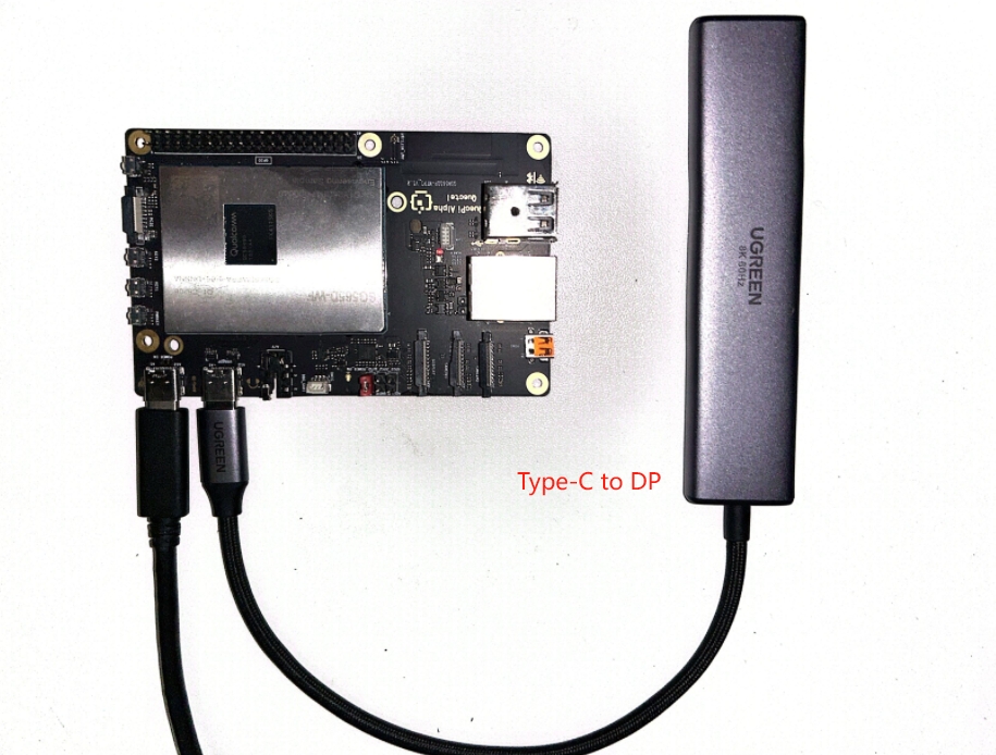
Quectel Pi H1 smart single-board computer supports connecting display screens through the Type-C to DP interface.
MIPI Screen Connection
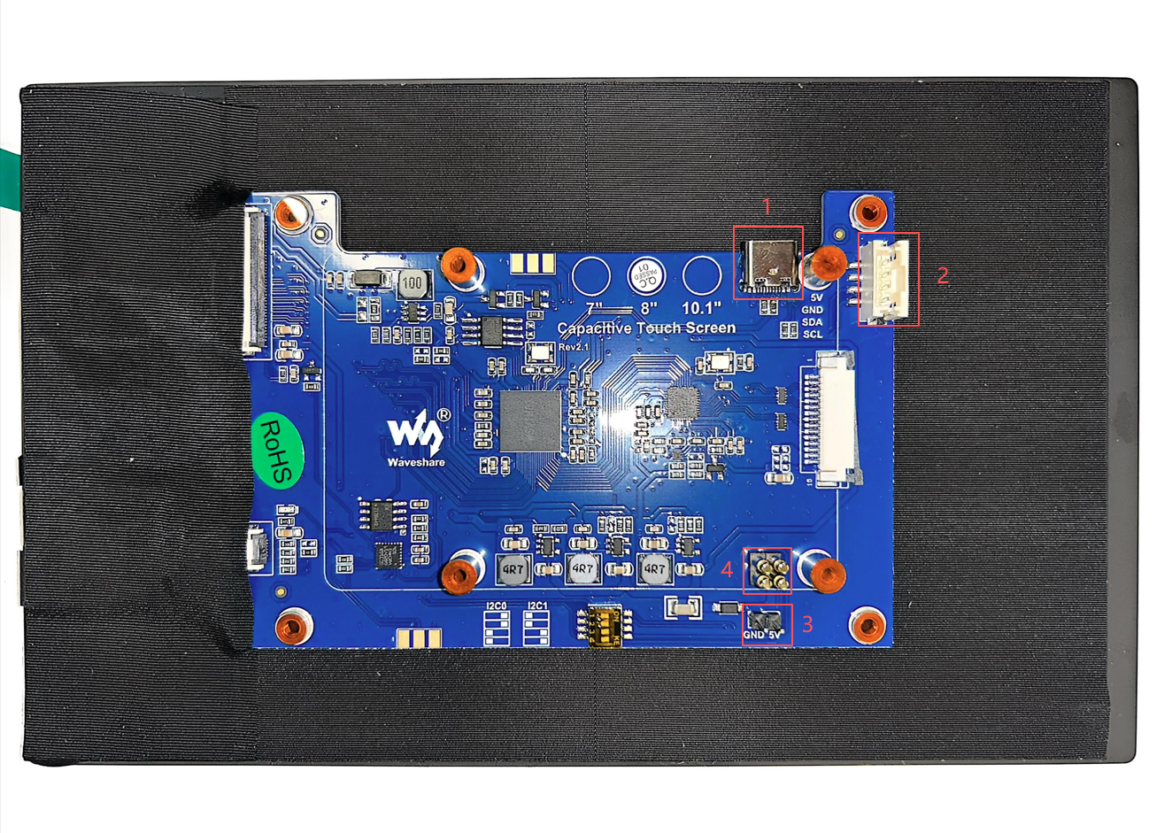
Connect according to the following diagram:
Note: This screen has 4 interfaces for power supply,any one can be selected,example selects“1”for power supply。
- namely type-C interface
- I2C communication and power supply interface
- 5V input and output interface
- I2C communication and power supply interface,need to align the screw holes with Quectel Pi H1 single board computer and tighten,Ensure the pins are firmly connected to 40PIN
Waveshare 8 inch MIPI Display Screen Back
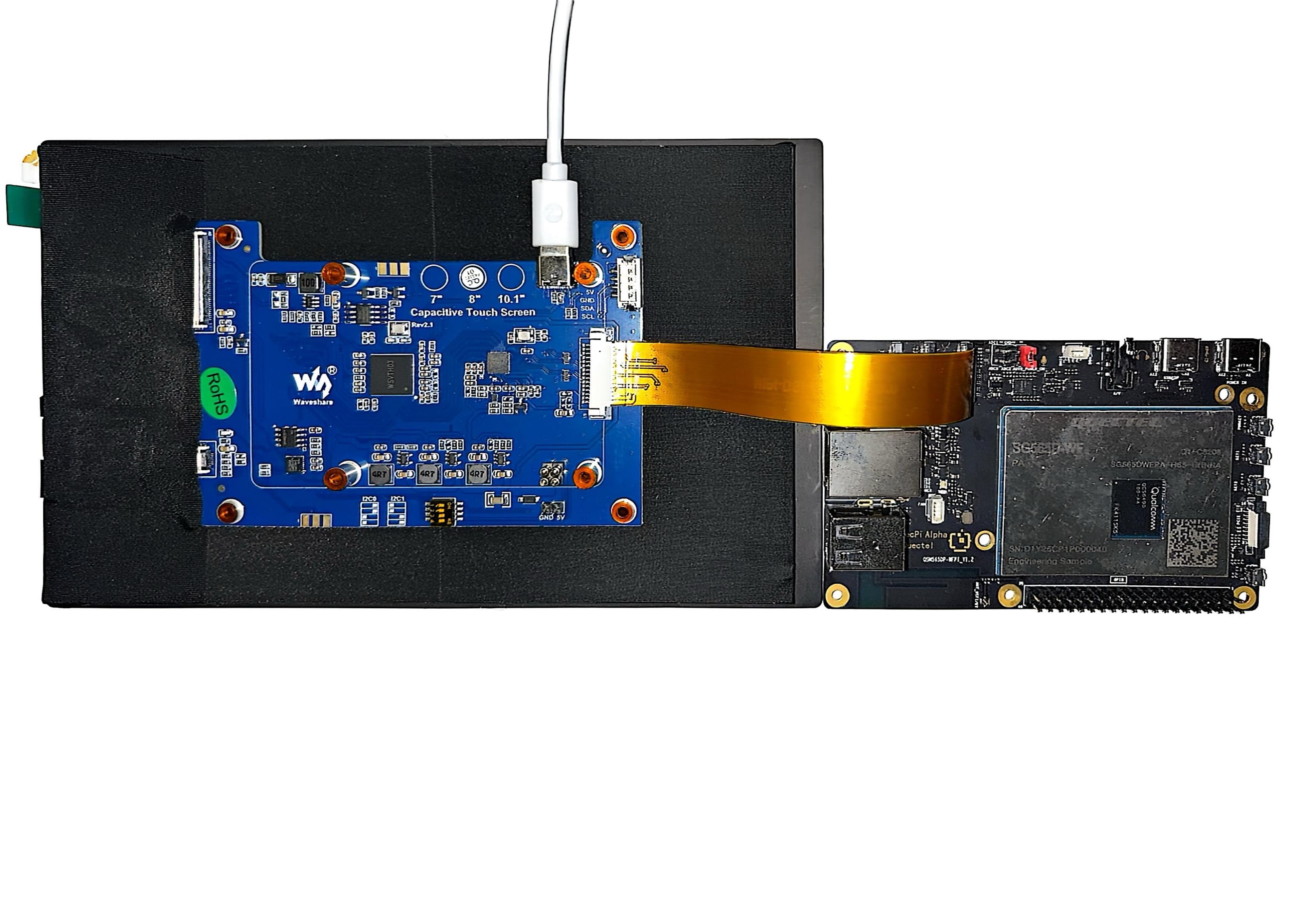
Quectel Pi H1 after connecting MIPI display screen
MIPI Screen Display Weston Desktop
After connecting the DP display and powering on, start the display service: systemctl start init_display. The DP screen will display the Weston desktop.
The display effect is shown in the figure below:
Play Video Using DP Screen
Execute video playback command:
mount -o rw,remount /
export XDG_RUNTIME_DIR=/dev/socket/weston
export WAYLAND_DISPLAY=wayland-1
gst-launch-1.0 -e filesrc location=/root/quectel.mp4 ! qtdemux ! \
    queue ! h264parse ! v4l2h264dec capture-io-mode=5 output-io-mode=5 ! \
    waylandsink enable-last-sample=false fullscreen=true
    # Modify the path after location according to the actual video path
Command description:
gst-launch-1.0: This is the command-line tool of GStreamer,for starting a GStreamer pipeline. The -e parameter means exit when the pipeline ends,rather than continuing to run。filesrc location=/root/quectel.mp4: filesrc is used to read data from file. location=/root/quectel.mp4 specifies the file path to read.! qtdemux: ! is a connection symbol,used to connect the output of the previous element to the input of the next element. qtdemux is used to demultiplex MP4 files. MP4 files usually contain video and audio streams. qtdemux is used to separate these streams for subsequent processing.! queue: queue is a buffer queue element,used to buffer data in the pipeline. It can alleviate the problem of inconsistent data processing speeds. For example, when the decoder processing speed is slow,queue can temporarily store data to avoid data loss.! h264parse: h264parse is used to parse H.264 video streams. It reorganizes the H.264 video stream data into a format suitable for decoder processing.! v4l2h264dec capture-io-mode=5 output-io-mode=5: v4l2h264dec is used to decode H.264 video streams. capture-io-mode=5 is used to set the capture input mode to 5, which is usually related to hardware acceleration. The specific meaning depends on the hardware and driver. output-io-mode=5 sets the mode to 5, and it is also related to hardware acceleration.! waylandsink enable-last-sample=false fullscreen=true: waylandsink is used to output the decoded video to the Wayland display server. enable-last-sample=false disables the "last sample" function, which is usually used to optimize performance or avoid certain issues. fullscreen=true displays the video in full screen mode.
The video playback effect is shown in the figure below:

Camera Solutions
MIPI Camera (IMX219) Testing
Quectel Pi H1 smart single-board computer supports MIPI interface camera. Below we select a Waveshare imx219 CSI interface CMOS camera as an example for testing.
Camera Connection
Connect according to the following diagram. When connecting, pull up the black lock part of the connector, insert the FPC cable into the first CSI slot. Note that the metal contact surface faces the metal contact surface inside the board. Press the lock to confirm that the FPC cable is stable and not loose.
Prerequisites
Run the following command in the SSH terminal:
mount -o rw,remount /
export XDG_RUNTIME_DIR=/dev/socket/weston
export WAYLAND_DISPLAY=wayland-1
Single-Camera Stream Startup
- Run the following command in the device terminal.
gst-launch-1.0 -e qtiqmmfsrc name=camsrc ! 'video/x-raw(memory:GBM),format=NV12,width=1280,height=720,framerate=30/1' ! fakesink
- This example demonstrates how to use 720p@30 FPS configuration to start the camera. This command uses fakesink (a virtual sink) as the output. Fakesink receives frame data from the camera sensor but performs no processing and discards it directly. Consequently, no content is saved on the device. This command is solely used for testing whether the camera is functioning properly. If the gst pipeline status changes to “PLAYING”,as shown below,it means the camera is running.
gbm_create_device(187): Info: backend name is: msm_drm
Setting pipeline to PAUSED ...
Pipeline is live and does not need PREROLL ...
Setting pipeline to PLAYING ...
New clock: GstSystemClock
- If you want to display the camera captured image in real time, please connect the HDMI screen in advance and execute the following command:
gst-launch-1.0 -e qtiqmmfsrc name=camsrc camera=0 ! 'video/x-raw(memory:GBM),format=NV12,width=1280,height=720,framerate=30/1' ! waylandsink
- camera=0 means using the first CSI interface camera; camera=1 means using the second CSI interface camera.
- If you want to display in full screen, add
fullscreen=trueafter the command. - To stop the camera stream, press
CTRL+C.
Preview + Video Recording
- Run the following command in the device terminal:
gst-launch-1.0 -e qtiqmmfsrc name=camsrc camera=0 video_1::type=preview ! 'video/x-raw,format=NV12,width=1280,height=720,framerate=30/1',compression=ubwc,interlace-mode=progressive,colorimetry=bt601 ! tee name=t ! queue ! waylandsink fullscreen=true t. ! queue ! v4l2h264enc capture-io-mode=5 output-io-mode=5 extra-controls="controls,video_bitrate=6000000,video_bitrate_mode=0;" ! queue ! h264parse ! mp4mux ! filesink location=/opt/mux_avc.mp4
- This command uses 720p 30 FPS configuration to start the camera,and saves it as a video file after h264 video encoding. If the gst pipeline status changes to “PLAYING”,it means the camera is running.
- To stop camera recording, press
CTRL+C. - MP4 file is saved in the /opt/ directory.
Command description:
! is a connection symbol,used to connect the output of the previous element to the input of the next element.
gst-launch-1.0: This is the command-line tool of GStreamer,for starting a GStreamer pipeline. The -e parameter means exit when the pipeline ends,rather than continuing to run.qtiqmmfsrc name=camsrc camera=0: Qualcomm platform-specific camera source plugin, collecting video from device camera=0 (main camera).video_1::type=preview: This is the attribute configuration of the qtiqmmfsrc element. For the video_1 stream (different cameras may have multiple streams, such as preview stream, capture stream, etc.), set its type to preview (preview stream), indicating that the subsequent processing is a video stream for real-time preview scenarios. Generally, parameters such as frame rate and resolution will be adapted to preview requirements.video/x-raw,format=NV12,width=1280,height=720,framerate=30/1: video/x-raw (raw video), NV12 (YUV 4:2:0, single-plane format, commonly used in video encoding), resolution 1280×720 (720p), frame rate 30fps.compression=ubwc,interlace-mode=progressive,colorimetry=bt601: Enable Qualcomm's UBWC(Ultra Bandwidth Compression) technology,reduce memory bandwidth requirements through hardware compression,and perform progressive scan (non-interlaced). The color space is ITU-R BT.601 (suitable for standard definition video).tee name=t: Splitter (tee) element, used to copy one input data stream into multiple streams, convenient for different processing of the same video stream (here one stream is used for preview display, and another stream is used for encoding storage). name=t names this tee element to t, so the subsequent other branches reference it by name to obtain the video stream.queue ! waylandsink fullscreen=true: queue:Queue element used to create a buffer queue in the pipeline,which decouples upstream and downstream elements and enables asynchronous processing. It can alleviate the problem of inconsistent processing speeds between upstream and downstream,avoiding blocking or frame dropping due to slow processing on one side.
waylandsink: Output sink element, and render and display videos on the screen in the Wayland display server environment.
fullscreen=true: Set waylandsink to display video in full screen mode.
t. ! queuet.: Use . syntax to reference the tee element which is previously named t to obtain the video stream for subsequent processing.
queue:Use the queue element again to buffer data and ensure smooth encoding and other links.
v4l2h264enc capture-io-mode=5 output-io-mode=5 extra-controls="controls,video_bitrate=6000000 video_bitrate_mode=0;": Use DMABUF (Direct Memory Access Buffer) for input, optimizing data transfer efficiency. Also use DMABUF to putput the encoded data. Target bitrate is 6 Mbps, using CBR (Constant Bit Rate) mode, suitable for network streaming or scenarios requiring stable bandwidth.queue ! h264parse ! mp4mux ! filesink location=/opt/mux_avc.mp4queue: Another queue element that continues to buffer encoded data and coordinates subsequent processing speed. Parse H.264 stream, add necessary NAL unit headers to meet MP4 encapsulation requirements. Encapsulate H.264 video stream as MP4 format and write data to the /opt/mux_avc.mp4 file.
Preview + Photo Capture
- Run the following command in the device terminal:
gst-pipeline-app -e qtiqmmfsrc name=camsrc camera=0 ! 'video/x-raw(memory:GBM),format=NV12,width=1280,height=720,framerate=30/1' ! waylandsink camsrc.image_1 ! "image/jpeg,width=1280,height=720,framerate=30/1" ! multifilesink location=/opt/frame%d.jpg async=false sync=true
- Press
Enterkey. This command will print the following menu and wait for user input.
##################################### MENU #####################################

============================== Pipeline Controls==============================
(0) NULL: Set the pipeline into NULL state
(1) READY: Set the pipeline into READY state
(2) PAUSED: Set the pipeline into PAUSED state
(3) PLAYING: Set the pipeline into PLAYING state

==================================== Other====================================
(p) Plugin Mode: Choose a plugin which to control
(q) Quit : Exit the application

Choose an option:
- Use the following menu steps to take a snapshot during preview.
(1) ready -> (3) Playing -> (Enter)-> (p)Plugin Mode : Select (5)camerasrc ->(36) capture-image -> (1): still – Snapshot ->(1) Snapshot count ('guint' value for arg1)
- To stop the camera, press
Enter, pressb(to return), then pressq(to quit). The captured snapshot images are saved in /opt/. By running the followingscpcommand on the host PC, you can extract the recorded content from the device:
scp -r root@[ip-addr]:/opt/<file name> .
- The generated file is shown in the figure below:

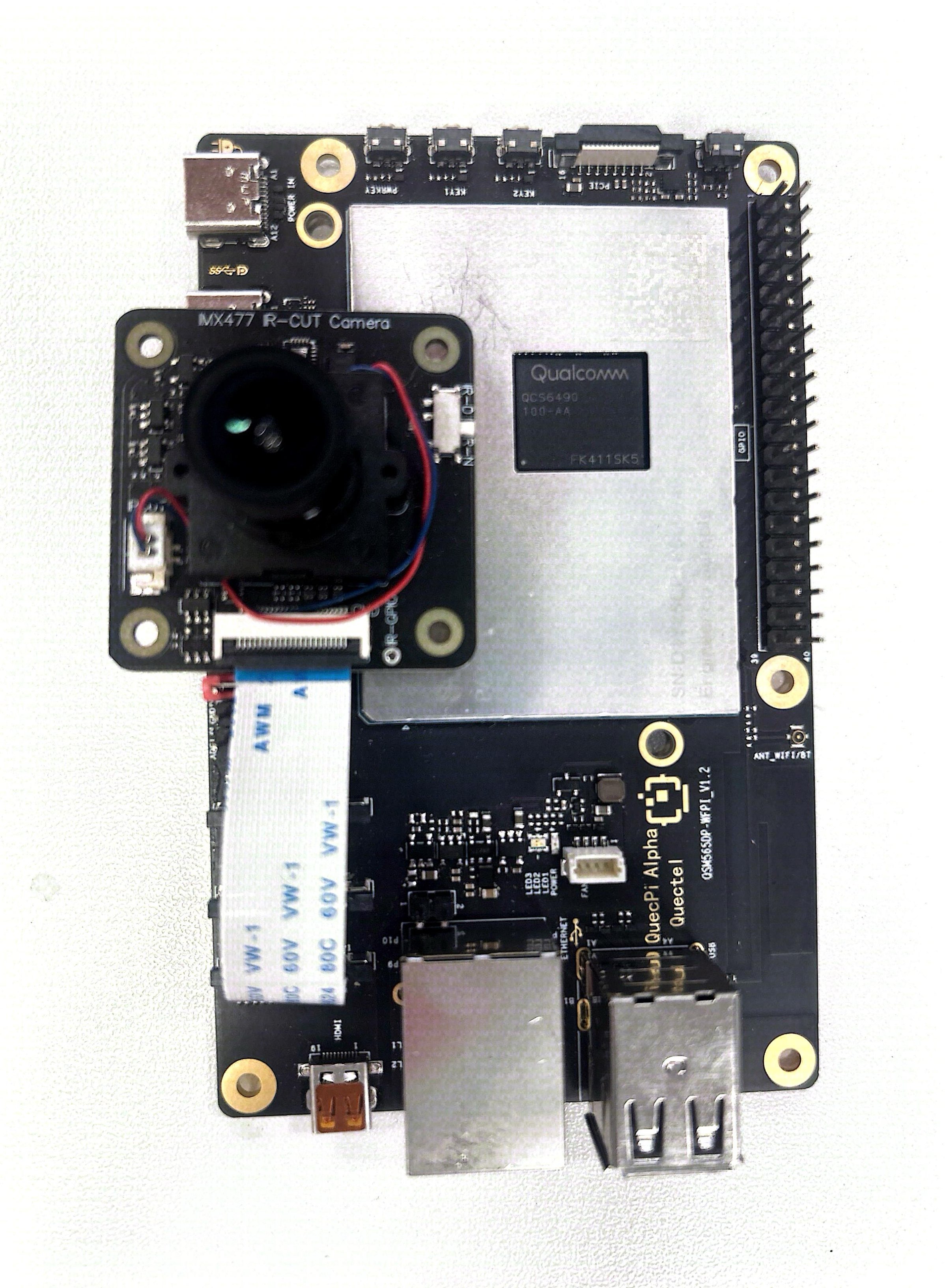
MIPI Camera (IMX477) Testing
Quectel Pi H1 smart single-board computer supports MIPI interface camera. Below we select a Waveshare imx477 CSI interface CMOS camera as an example for testing.
Camera Connection
Connect according to the following diagram. When connecting, pull up the black lock part of the connector, insert the FPC cable into the second CSI slot. Note that the metal contact surface faces the metal contact surface inside the board. Press the lock to confirm that the FPC cable is stable and not loose.
Prerequisites
Run the following command in the SSH terminal:
mount -o rw,remount /
export XDG_RUNTIME_DIR=/dev/socket/weston
export WAYLAND_DISPLAY=wayland-1
Single-Camera Stream Startup
- Run the following command in the device terminal.
gst-launch-1.0 -e qtiqmmfsrc name=camsrc camera=1 ! 'video/x-raw(memory:GBM),format=NV12,width=1280,height=720,framerate=30/1' ! fakesink
- This example demonstrates how to use 720p@30 FPS configuration to start the camera. This command uses fakesink (a virtual sink) as the output. Fakesink receives frame data from the camera sensor but performs no processing and discards it directly. Consequently, no content is saved on the device. This command is solely used for testing whether the camera is functioning properly. If the gst pipeline status changes to “PLAYING”,as shown below,it means the camera is running.
gbm_create_device(187): Info: backend name is: msm_drm
Setting pipeline to PAUSED ...
Pipeline is live and does not need PREROLL ...
Setting pipeline to PLAYING ...
New clock: GstSystemClock
- If you want to display the camera captured image in real time, please connect the HDMI screen in advance and execute the following command:
gst-launch-1.0 -e qtiqmmfsrc name=camsrc camera=1 ! 'video/x-raw(memory:GBM),format=NV12,width=1280,height=720,framerate=30/1' ! waylandsink
- camera=0 means using the first CSI interface camera; camera=1 means using the second CSI interface camera.
- If you want to display in full screen, add
fullscreen=trueafter the command. - To stop the camera stream, press
CTRL+C.
Preview + Video Recording
- Run the following command in the device terminal:
gst-launch-1.0 -e qtiqmmfsrc name=camsrc camera=1 video_1::type=preview ! 'video/x-raw,format=NV12,width=1280,height=720,framerate=30/1',compression=ubwc,interlace-mode=progressive,colorimetry=bt601 ! tee name=t ! queue ! waylandsink fullscreen=true t. ! queue ! v4l2h264enc capture-io-mode=5 output-io-mode=5 extra-controls="controls,video_bitrate=6000000,video_bitrate_mode=0;" ! queue ! h264parse ! mp4mux ! filesink location=/opt/mux_avc.mp4
- This command uses 720p 30 FPS configuration to start the camera,and saves it as a video file after h264 video encoding. If the gst pipeline status changes to “PLAYING”,it means the camera is running.
- To stop camera recording, press
CTRL+C. - The MP4 file is saved in the /opt/ directory.
Command description:
! is a connection symbol,used to connect the output of the previous element to the input of the next element.
gst-launch-1.0: This is the command-line tool of GStreamer,for starting a GStreamer pipeline. The -e parameter means exit when the pipeline ends,rather than continuing to run.qtiqmmfsrc name=camsrc camera=1: Qualcomm platform-specific camera source plugin, collecting video from device camera=1 (secondary camera).video_1::type=preview: This is the attribute configuration of the qtiqmmfsrc element. For the video_1 stream (different cameras may have multiple streams, such as preview stream, capture stream, etc.), set its type to preview (preview stream), indicating that the subsequent processing is a video stream for real-time preview scenarios. Generally, parameters such as frame rate and resolution will be adapted to preview requirements.video/x-raw,format=NV12,width=1280,height=720,framerate=30/1: video/x-raw (raw video), NV12 (YUV 4:2:0, single-plane format, commonly used in video encoding), resolution 1280×720 (720p), frame rate 30fps.compression=ubwc,interlace-mode=progressive,colorimetry=bt601: Enable Qualcomm's UBWC(Ultra Bandwidth Compression) technology,reduce memory bandwidth requirements through hardware compression,and perform progressive scan(non-interlaced). The color space is ITU-R BT.601 (suitable for standard definition video).tee name=t: Splitter (tee) element, used to copy one input data stream into multiple streams, convenient for different processing of the same video stream (here one stream is used for preview display, one stream is used for encoding storage). name=t names this tee element to t, so subsequent other branches reference it by name to obtain the video stream.queue ! waylandsink fullscreen=true: queue:Queue element used to create a buffer queue in the pipeline,which decouples upstream and downstream elements and enables asynchronous processing. It can alleviate the problem of inconsistent processing speeds between upstream and downstream,avoiding blocking or frame dropping due to slow processing on one side.
waylandsink: Output the sink element, used to render and display videos on the screen in the Wayland display server environment.
fullscreen=true: Set waylandsink to display video in full screen mode.
t. ! queuet.: Use . syntax to reference the tee element which is previously named t to obtain the video stream for subsequent processing.
queue:Use the queue element again to buffer data and ensure smooth encoding and other links.
v4l2h264enc capture-io-mode=5 output-io-mode=5 extra-controls="controls,video_bitrate=6000000 video_bitrate_mode=0;": Use DMABUF (Direct Memory Access Buffer) for input, optimizing data transfer efficiency. Also use DMABUF to output the encoded data. Target bitrate is 6 Mbps, using CBR (Constant Bit Rate) mode, suitable for network streaming or scenarios requiring stable bandwidth.queue ! h264parse ! mp4mux ! filesink location=/opt/mux_avc.mp4queue: Another queue element that continues to buffer encoded data and coordinates subsequent processing speed. Parse H.264 stream, and add necessary NAL unit headers to meet MP4 encapsulation requirements. Encapsulate H.264 video stream as MP4 format and write data to the /opt/mux_avc.mp4 file.
Preview + Photo Capture
- Run the following command in the device terminal:
gst-pipeline-app -e qtiqmmfsrc name=camsrc camera=1 ! 'video/x-raw(memory:GBM),format=NV12,width=1280,height=720,framerate=30/1' ! waylandsink camsrc.image_1 ! "image/jpeg,width=1280,height=720,framerate=30/1" ! multifilesink location=/opt/frame%d.jpg async=false sync=true
- Press
Enterkey. This command will print the following menu and wait for user input.
##################################### MENU #####################################

============================== Pipeline Controls==============================
(0) NULL: Set the pipeline into NULL state
(1) READY: Set the pipeline into READY state
(2) PAUSED: Set the pipeline into PAUSED state
(3) PLAYING: Set the pipeline into PLAYING state

==================================== Other====================================
(p) Plugin Mode: Choose a plugin which to control
(q) Quit : Exit the application

Choose an option:
- Use the following menu steps to take a snapshot during preview.
(1) ready -> (3) Playing -> (Enter)-> (p)Plugin Mode : Select (5)camerasrc ->(36) capture-image -> (1): still – Snapshot ->(1) Snapshot count ('guint' value for arg1)
- To stop the camera, press
Enter, pressb(to return), then pressq(to quit). The captured snapshot images are saved in /opt/. By running the followingscpcommand on the host PC, you can extract the recorded content from the device:
scp -r root@[ip-addr]:/opt/<file name> .
- The generated file is shown in the figure below:
Dual-Camera Stream Stitching Display
Two streams obtained from the main camera and auxiliary camera (both are 720p). The two streams are sent to be combined side by side and then displayed.
gst-launch-1.0 -e qtivcomposer name=mixer sink_0::position="<0, 0>" sink_0::dimensions="<640, 360>" sink_1::position="<640, 0>" sink_1::dimensions="<640, 360>" mixer. ! queue ! waylandsink enable-last-sample=false fullscreen=true qtiqmmfsrc name=camsrc_0 camera=0 ! video/x-raw\(memory:GBM\), format=NV12, width=1280, height=720, framerate=30/1, compression=ubwc ! mixer. qtiqmmfsrc name=camsrc_1 camera=1 ! video/x-raw\(memory:GBM\), format=NV12, width=1280, height=720, framerate=30/1, compression=ubwc ! mixer.
- To stop the camera stream, press
CTRL+C.
USB Camera Testing
Quectel Pi H1 smart single-board computer supports USB interface cameras. Below we select a Waveshare OV5693 5MP USB interface camera as an example for testing.
Camera Connection
Insert the USB camera connection cable into the Quectel Pi H1 type-A interface.
View Related Information
- Run the following command in the SSH terminal. You can view the USB device information recognized by the system:
dmesg | grep usb
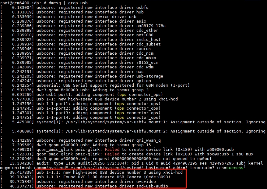
- Run the following command in the SSH terminal. You can view newly added device nodes:
v4l2-ctl --list-devices
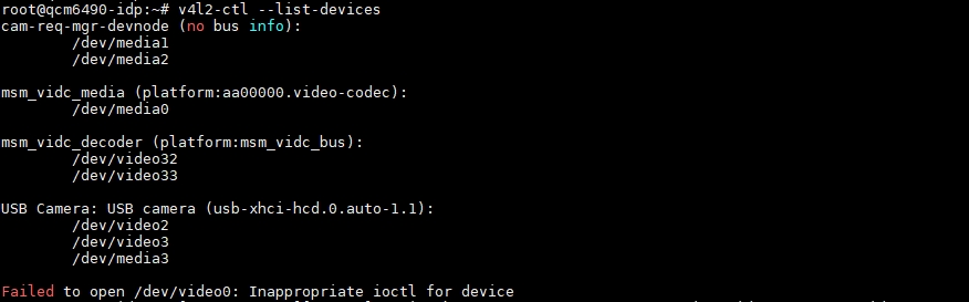
- /dev/video2 —— Main video node, the gst command mainly operates on this node
- /dev/video3 —— Metadata node
- /dev/media3 —— Hardware topology controller that controls the entire pipeline
- Run the following command in the SSH terminal to view the formats supported by the video node:
v4l2-ctl --list-formats-ext --device /dev/video2
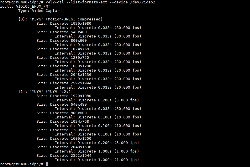
- From the figure, it can be seen that the camera supports MJPG and YUYV of image output.
Prerequisites
After connecting the HDMI screen, run the following command in the SSH terminal:
mount -o rw,remount /
export XDG_RUNTIME_DIR=/dev/socket/weston
export WAYLAND_DISPLAY=wayland-1
Real-time Preview
- Run the following command in the device terminal:
- MJPG format (resolution and frame rate must match the modes supported by the camera)
gst-launch-1.0 v4l2src device=/dev/video2 ! image/jpeg,width=1280,height=720,framerate=30/1 ! jpegdec ! videoconvert ! waylandsink fullscreen=true - YUYV format (Resolution and frame rate must match the modes supported by the camera. In GStreamer, the identifier for this format is YUY2.)
gst-launch-1.0 v4l2src device=/dev/video2 ! video/x-raw,format=YUY2,width=1280,height=720,framerate=10/1 ! videoconvert ! waylandsink fullscreen=true
Command description:
- gst-launch-1.0 -e
Start pipeline. -e ensures that pressing Ctrl+C can properly terminate when stopping (EOS).
- v4l2src device=/dev/video2
Capture data from /dev/video2 of V4L2 device.
- image/jpeg,width=1280,height=720,framerate=30/1
Require camera to output 1280×720@30 fps MJPEG. If the camera does not support this, the pipeline will directly report an error.
- jpegdec
Decode MJPEG frames into original YUV/RGB pixel data.
- videoconvert
Convert data of pixel format to format suitable for Wayland display(usually NV12/BGRx).
- waylandsink fullscreen=true
Use Wayland as the display backend,and set the window to full screen (no title bar and in full screen).
Preview + Video Recording
- Run the following command in the device terminal:
gst-launch-1.0 -e v4l2src device=/dev/video2 io-mode=2 ! \
  image/jpeg,width=1280,height=720,framerate=30/1 ! \
  jpegdec ! videoconvert ! tee name=t \
  t. ! queue ! v4l2h264enc ! h264parse ! mp4mux ! filesink location=/opt/out.mp4 \
  t. ! queue ! videoconvert ! waylandsink  fullscreen=true sync=false
- This command uses 720p 30 FPS configuration to start the camera,and saves it as a video file after h264 video encoding. If the gst pipeline status changes to "PLAYING",it means the camera is running.
- To stop camera recording, press
CTRL+C. - MP4 file is saved in /opt/ directory.
Command description:
- v4l2src device=/dev/video2 io-mode=2
Capture video stream from /dev/video2 device; io-mode=2 indicates using memory mapping(mmap)mode to improve performance.
- image/jpeg,width=1280,height=720,framerate=30/1
Specify the captured video stream format as MJPEG,resolution is 1280×720,frame rate is 30fps.
- jpegdec
Decode MJPEG format video stream and convert it to original RGB/YUV format.
- videoconvert
Convert the decoded video format to a format suitable for subsequent processing (for example, convert from YUV to RGBA).
- tee name=t
Split one video stream into two streams, which can subsequently be referenced through t. to reference these two streams.
- t. ! queue
Extract one stream from the tee element and buffer it through the queue element.
- v4l2h264enc
Encode the video stream to H.264 format.
- h264parse
Parse H.264 encoded video stream to meet the requirements of MP4 file format.
- mp4mux
Package the H.264 video stream into MP4 file format.
- filesink location=/opt/out.mp4:
Save the packaged MP4 file to /opt/out.mp4.
- t. ! queue
Extract another stream from the tee element and buffer it through the queue element.
- videoconvert
Convert the video format to a format suitable for Wayland display.
- waylandsink fullscreen=true sync=false
Output the video stream to the Wayland display, display video in full screen mode, disable sync mode, and avoid Wayland display waiting for data stream, thereby improving display performance.
- To play the video file, run the following command in the device terminal:
gst-launch-1.0 -e filesrc location=/opt/out.mp4 ! qtdemux ! queue ! h264parse ! v4l2h264dec capture-io-mode=5 output-io-mode=5 ! videocrop top=0 bottom=40 left=0 right=0 ! videoconvert ! waylandsink fullscreen=true enable-last-sample=false
Command description:
- filesrc location=/opt/out.mp4
Read data from the /opt/out.mp4 file.
- qtdemux
Separate the video and audio streams from the MP4 file.
- queue
Buffer data to avoid data loss during processing.
- h264parse
Parse the H.264 encoded data of the video stream.
- v4l2h264dec capture-io-mode=5 output-io-mode=5
Use V4L2 decoder to decode H.264 video stream. capture-io-mode=5 and output-io-mode=5 are hardware acceleration related parameters.
- videocrop top=0 bottom=40 left=0 right=0
Due to automatic alignment of video stream, additional pixel information is filled, causing a green border at the bottom of the video. Therefore, crop the bottom 40 pixels.
- videoconvert
Format conversion element to ensure the cropped video stream format is suitable for Wayland display.
- waylandsink fullscreen=true enable-last-sample=false
Output the decoded video to the Wayland display and set to full screen mode, while disabling the last frame display.
Preview + Photo Capture
- Run the following command in the device terminal:
gst-launch-1.0 -e v4l2src device=/dev/video2 io-mode=2 ! \
  image/jpeg,width=1280,height=720,framerate=30/1 ! \
  tee name=t \
  t. ! queue ! jpegdec ! videoconvert ! waylandsink sync=false \
  t. ! queue ! multifilesink location=/opt/shot-%05d.jpg max-files=5
- Press
CTRL+Cto automatically save the last 5 images.
Command description:
- v4l2src device=/dev/video2 io-mode=2
Capture MJPEG data from USB camera.
- image/jpeg,width=1280,height=720,framerate=30/1
Require camera to output 1280×720@30 fps MJPEG stream.
- tee name=t
Split the same stream into multiple streams, and subsequently use t. for reference.
- t. ! queue ! jpegdec ! videoconvert ! waylandsink sync=false
Preview branch: Decode MJPEG → Convert to RGB → Send to Wayland window for real-time display. sync=false reduces delay.
- t. ! queue ! multifilesink location=shot-%05d.jpg max-files=5
Photo capture branch: Save each frame as JPG unchanged,and the file name is automatically numbered to %05d (5 digits). max-files=5 means to only keep the latest 5 images, and that old files are automatically deleted.
- To view photos, enter the following command in the device terminal:
gst-launch-1.0 filesrc location=/opt/shot-00036.jpg ! jpegdec ! imagefreeze ! waylandsink fullscreen=true
- To quit viewing, press
CTRL+C.
Command description:
- filesrc location=/opt/shot-00036.jpg
Read /opt/shot-00036.jpg from the file system.
- jpegdec
Decode JPEG compressed data into original RGB/YUV pixel frames.
- imagefreeze
Only keep the first frame, and continuously repeat this frame to achieve a "still image" effect.
- waylandsink fullscreen=true
Send the image to Wayland compositor for full screen display.
Storage Devices
NVMe SSD Partitioning, Formatting and Mounting
This article introduces how to partition, format, and mount NVMe solid state drive and test its performance (using /dev/nvme0n1 as an example) in Linux system.
Partitioning Operation (Using fdisk)
Partition the NVMe device using the fdisk tool. The steps are as follows:
Enter Partition Interactive Interface
Execute the following command to start fdisk and specify the target NVMe device:
fdisk /dev/nvme0n1
Interactive Interface Operation Steps
After entering fdisk interactive mode, execute commands in the following order:
Create GPT Partition Table
Enter g and press Enter to create the GUID partition table (GPT). It is suitable for large capacity devices (recommended):
Command (m for help): g
Created a new GPT disklabel (GUID: XXXXXXXX-XXXX-XXXX-XXXX-XXXXXXXXXXXX)
Create Partition
Enter n and press Enter to create a partition. Subsequent parameters (partition number, start sector, end sector) can remain default (All available space is used by default):
Command (m for help): n
Partition number (1-128, default 1):
First sector (2048-xxxxxxxxx, default 2048):
Last sector, +/-sectors or +/-size{K,M,G,T,P} (2048-xxxxxxxxx, default xxxxxx):
Created a new partition 1 of type 'Linux filesystem' and of size XX GiB.
Write Partition Table and Exit
Enter w and press Enter to write the partition configuration to the device and quit fdisk:
Command (m for help): w
The partition table has been altered.
Calling ioctl() to re-read partition table.
Syncing disks.
After the operation is complete, the system will generate a new partition /dev/nvme0n1p1(p1 indicates the first partition).
Format Partition (EXT4 format)
Use the mkfs.ext4 tool to format the new partition as EXT4 file system (suitable for most Linux environments):
mkfs.ext4 /dev/nvme0n1p1
After execution, formatting progress will be displayed. After completion, similar information will be output:
mke2fs 1.46.5 (30-Dec-2021)
Creating filesystem with 12345678 4k blocks and 3456789 inodes
Filesystem UUID: xxxxxxxx-xxxx-xxxx-xxxx-xxxxxxxxxxxx
Superblock backups stored on blocks:
  32768, 98304, 163840, ...
Allocating group tables: done
Writing inode tables: done
Creating journal (65536 blocks): done
Writing superblocks and filesystem accounting information: done
Manually Mount Partition
Create Mount Directory
Use the mkdir command to create a directory for mounting SSD (example path is /mnt/myssd):
mkdir -p /mnt/myssd
Mount Partition
Mount the /dev/nvme0n1p1 partition to the /mnt/myssd directory:
mount /dev/nvme0n1p1 /mnt/myssd
You can verify whether the mount is successful using the df -h command. If it contains /dev/nvme0n1p1 and /mnt/myssd, it means the mount is normal:
df -h
Filesystem      Size  Used Avail Use% Mounted on
/dev/nvme0n1p1  100G   5G   95G   5% /mnt/myssd
Configure Automatic Mounting (takes effect after restart)
By modifying the /etc/fstab file to automatically mount partitions when the system starts:
Edit fstab File
Open /etc/fstab with an editor:
Add Mount Configuration
Add the following lines at the end of the file to specify the partition,mount point, file system type and parameters:
/dev/nvme0n1p1 /mnt/myssd ext4 defaults 0 2
Performance Testing (Read/Write Speed Verification)
Use the dd command to test SSD read/write performance (Ensure the partition is mounted during testing):
Read Speed Test
Create a temporary test file(if it already exists),and test read speed by reading the file to null device (/dev/null):
dd if=/mnt/myssd/testfile of=/dev/null bs=1G iflag=direct
Note: iflag=direct means to bypass system cache to test real read speed.
Output example:
1+0 records in
1+0 records out
1073741824 bytes (1.1 GB, 1.0 GiB) copied, 0.852345 s, 1.3 GB/s
Write Speed Test
Generate a 1 GB empty file (/dev/zero as zero data source) to test write speed:
dd if=/dev/zero of=/mnt/myssd/testfile bs=1G count=1 oflag=direct
Output example:
1+0 records in
1+0 records out
1073741824 bytes (1.1 GB, 1.0 GiB) copied, 1.245678 s, 862 MB/s
Temporary files can be deleted after testing:
rm /mnt/myssd/testfile
UFS Storage
Quectel Pi H1 embeds a 128 GB UFS storage chip. Compared to eMMC, its UFS has faster read/write speeds, supports full-duplex communication and command queuing, providing better performance.
View Capacity
You can query UFS partition information and capacity through the fdisk -l command:
root@qcm6490-idp:/opt/bc-1.08.1# fdisk -l
Disk /dev/sda: 116.09 GiB, 124646326272 bytes, 30431232 sectors
Disk model: C2G072
Units: sectors of 1 * 4096 = 4096 bytes
Sector size (logical/physical): 4096 bytes / 4096 bytes
I/O size (minimum/optimal): 4096 bytes / 4096 bytes
Disklabel type: gpt
Disk identifier: 49B3A77D-3D7D-22A5-0A10-6A2ECDDEA256

Device      Start      End  Sectors   Size Type
/dev/sda1       6   131077   131072   512M EFI System
/dev/sda2  131078   138757     7680    30M Linux filesystem
/dev/sda3  138758 30431226 30292469 115.6G Linux root (ARM-64)
View Partition Information
You can query UFS partition information through the df command, including usage, mount directory, and related details:
root@qcm6490-idp:/opt/bc-1.08.1# df -h
Filesystem      Size  Used Avail Use% Mounted on
/dev/sda3       109G  3.3G  101G   4% /sysroot
devtmpfs        4.0M     0  4.0M   0% /dev
tmpfs           3.6G     0  3.6G   0% /dev/shm
tmpfs           1.5G   31M  1.5G   3% /run
tmpfs           4.0M     0  4.0M   0% /sys/fs/cgroup
tmpfs           3.6G   12K  3.6G   1% /tmp
tmpfs           3.6G     0  3.6G   0% /var/volatile
/dev/sda1       511M  136M  376M  27% /boot
/dev/sda2        25M  892K   22M   4% /var/persist
tmpfs           737M     0  737M   0% /run/user/0
Performance Testing
Performance testing mainly measures the read/write speed of UFS storage in Linux systems, typically combining time and dd commands.
Test for Writing Files
root@qcm6490-idp:/opt# time dd if=/dev/zero of=tempfile bs=1M count=100 conv=fdatasync
100+0 records in
100+0 records out
104857600 bytes (105 MB, 100 MiB) copied, 0.2874 s, 365 MB/s

real    0m0.316s
user    0m0.000s
sys     0m0.122s
When using the dd command to write a file, the conv=fdatasync parameter should be added. This instructs dd to force the synchronization of all buffered data to the disk after the write operation is apparently complete. This is necessary because disk write operations typically write data to the kernel’s page cache first. The system call then returns immediately with success, even though the data may not yet be physically written to the disk. Using conv=fdatasync ensures that the command does not return until the data is confirmed to be written to the physical disk. Consequently, the speed measured by the test reflects the true disk write speed.
Test for Reading Files
In embedded systems, it is often necessary to test file system read/write performance. When reading files, the system uses cache by default. This can lead to inaccurate test results because reading data from cache is significantly faster than reading directly from the disk. To measure the true disk read speed by ignoring the cache effect, parameters iflag=direct,nonblock can be specified.
root@qcm6490-idp:/opt# time dd if=tempfile of=/dev/null bs=1M count=100 iflag=direct,nonblock
100+0 records in
100+0 records out
104857600 bytes (105 MB, 100 MiB) copied, 0.196993 s, 532 MB/s

real    0m0.201s
user    0m0.001s
sys     0m0.041s
Thus, it is shown that the direct read speed from the disk is 532 MB/s.
Core Resources and Performance
CPU Metrics and Testing
Quectel Pi H1 smart single-board computer uses Qualcomm QCS6490 as the core processor,based on Arm v8 Cortex ,with a maximum frequency of 2.7 GHz.
- View CPU Information Command
root@qcm6490-idp:/# cat /proc/cpuinfo
processor       : 0
BogoMIPS        : 38.40
Features        : fp asimd evtstrm aes pmull sha1 sha2 crc32 atomics fphp asimdhp cpuid asimdrdm lrcpc dcpop asimddp
CPU implementer : 0x41
CPU architecture: 8
CPU variant     : 0x2
CPU part        : 0xd05
CPU revision    : 0

processor       : 1
BogoMIPS        : 38.40
Features        : fp asimd evtstrm aes pmull sha1 sha2 crc32 atomics fphp asimdhp cpuid asimdrdm lrcpc dcpop asimddp
CPU implementer : 0x41
CPU architecture: 8
CPU variant     : 0x2
CPU part        : 0xd05
CPU revision    : 0
- processor: The logical processing core number of the system. For multi-core processors, it can be a physical core or a virtual logical core using hyperthreading technology
- BogoMIPS: The CPU's Million Instructions Per Second (MIPS) roughly calculated during system kernel startup
- View CPU Usage
After executing top, press 1 to display the usage rate of each CPU core
root@qcm6490-idp:/# top
top - 00:20:05 up 20 min,  1 user,  load average: 0.04, 0.07, 0.06
Tasks: 340 total,   1 running, 339 sleeping,   0 stopped,   0 zombie
%Cpu0  :  0.5 us,  1.6 sy,  0.0 ni, 97.3 id,  0.0 wa,  0.5 hi,  0.0 si,  0.0 st
%Cpu1  :  0.5 us,  0.0 sy,  0.0 ni, 98.9 id,  0.0 wa,  0.5 hi,  0.0 si,  0.0 st
%Cpu2  :  1.6 us,  0.0 sy,  0.0 ni, 97.3 id,  0.5 wa,  0.0 hi,  0.0 si,  0.5 st
%Cpu3  :  0.0 us,  0.5 sy,  0.0 ni, 98.4 id,  0.0 wa,  0.5 hi,  0.0 si,  0.5 st
%Cpu4  :  1.1 us,  0.0 sy,  0.0 ni, 98.4 id,  0.0 wa,  0.0 hi,  0.0 si,  0.5 st
%Cpu5  :  0.0 us,  0.0 sy,  0.0 ni,100.0 id,  0.0 wa,  0.0 hi,  0.0 si,  0.0 st
%Cpu6  :  0.0 us,  0.0 sy,  0.0 ni,100.0 id,  0.0 wa,  0.0 hi,  0.0 si,  0.0 st
%Cpu7  :  0.0 us,  0.0 sy,  0.0 ni,100.0 id,  0.0 wa,  0.0 hi,  0.0 si,  0.0 st
MiB Mem :   7366.7 total,   6386.2 free,    498.6 used,    481.9 buff/cache
MiB Swap:   5395.5 total,   5395.5 free,      0.0 used.   6698.9 avail Mem

    PID USER      PR  NI    VIRT    RES    SHR S  %CPU  %MEM     TIME+ COMMAND
      1 root      20   0  162028   9468   6524 S   1.1   0.1   0:07.64 systemd
    594 message+  20   0    6904   3712   3328 S   1.1   0.0   0:06.46 dbus-daemon
   1087 root      20   0 1794556  61472  30848 S   1.1   0.8   0:05.56 containerd
   1816 root      20   0    5768   2688   2048 R   1.1   0.0   0:00.04 top
     40 root      20   0       0      0      0 I   0.5   0.0   0:00.48 kworker/3:0-mm_percpu_wq
     50 root      20   0       0      0      0 S   0.5   0.0   0:00.55 rcuop/4
    127 root      20   0       0      0      0 I   0.5   0.0   0:00.47 kworker/u16:6-events_unbound
    280 root      20   0   34988  15176  14792 S   0.5   0.2   0:05.38 systemd-journal
    925 root      20   0  630136  72200  53256 S   0.5   1.0   0:06.65 weston
- %us:CPU usage of user space programs(without nice scheduling)
- %sy:CPU usage of system space,mainly kernel programs
- %ni:CPU usage of user space programs that have been scheduled through nice
- %id:Idle CPU
- %wa: CPU time percentage waiting for input/output
- %hi: Number of hard interrupts processed by CPU
- %si: Number of soft interrupts processed by CPU
- %st: Real-time
- Get CPU Temperature Information
root@qcm6490-idp:/# cat /sys/class/thermal/thermal_zone0/temp
37000
- The current temperature value is one thousandth of the displayed value above (Unit: degrees Celsius).
- CPU Stress Testing
There are many ways to test CPU stress. You can use the bc command to calculate pi to test the stability of the CPU during computation.
root@qcm6490-idp:/# echo "scale=5000; 4*a(1)" | bc -l -q &
[1] 1592
The above command runs the pi calculation in the background, accurate to 5000 digits. The calculation process takes some time.
At this time, we can check the change in CPU utilization through the top command, as shown below:
root@qcm6490-idp:/# top
top - 06:42:14 up 8 min,  1 user,  load average: 0.29, 0.16, 0.09
Tasks: 326 total,   3 running, 323 sleeping,   0 stopped,   0 zombie
%Cpu(s): 12.7 us,  0.2 sy,  0.0 ni, 86.8 id,  0.0 wa,  0.1 hi,  0.0 si,  0.2 st
MiB Mem :   7366.9 total,   6540.2 free,    439.5 used,    387.2 buff/cache
MiB Swap:   5395.7 total,   5395.7 free,      0.0 used.   6770.1 avail Mem

    PID USER      PR  NI    VIRT    RES    SHR S  %CPU  %MEM     TIME+ COMMAND
   1592 root      20   0    3052   1792   1536 R  99.7   0.0   0:14.37 bc
    588 message+  20   0    6908   3584   3200 S   0.7   0.0   0:03.06 dbus-da+
      1 root      20   0  162064   9324   6380 S   0.3   0.1   0:04.26 systemd
...
About 15 seconds later, the pi result is calculated. During this period, if CPU usage reaches 100% with no abnormalities occurred,it indicates that the CPU stress test passed. You can continue to increase the precision value, to further increase the CPU stress test intensity.
root@qcm6490-idp:/# 3.141592653589793238462643383279502884197169399375105820974944592307\
81640628620899862803482534211706798214808651328230664709384460955058\
22317253594081284811174502841027019385211055596446229489549303819644\
...
Memory Status
- View Memory Information
root@qcm6490-idp:/opt/bc-1.08.1# cat /proc/meminfo
MemTotal:        7543736 kB
MemFree:         6664720 kB
MemAvailable:    6928688 kB
Buffers:           19768 kB
Cached:           380520 kB
SwapCached:            0 kB
Active:            52044 kB
Inactive:         462332 kB
Active(anon):       3588 kB
Inactive(anon):   142568 kB
Active(file):      48456 kB
Inactive(file):   319764 kB
- MemTotal: All available RAM size, physical memory minus reserved digits and kernel usage
- MemFree: LowFree + HighFree
- Buffers: Size used for caching block devices
- Cached: File buffer size
- SwapCached: Memory that has been swapped out, related to I/O
- Active: Frequently (recently) used memory
- Inactive: Memory that is not frequently used recently
- Get Memory Usage
root@qcm6490-idp:/opt/bc-1.08.1# free -m
               total        used        free      shared  buff/cache   available
Mem:            7366         437        6504          31         424        6763
Swap:           5395           0        5395
- total :Total memory
- used :Amount of memory used
- free :Amount of memory available
- Memory Stress Testing
By specifying the memory size and number of tests, stress testing can be performed on the system's existing memory. You can use the system tool memtester for testing. For example, specify memory size to 300 MB and number of tests to 1, then the test command is "memtester 300M 1".
The following uses 300 MB memory space, single test as an example:
root@qcm6490-idp:/# memtester 300M 1
memtester version 4.5.1 (64-bit)
Copyright (C) 2001-2020 Charles Cazabon.
Licensed under the GNU General Public License version 2 (only).

pagesize is 4096
pagesizemask is 0xfffffffffffff000
want 300MB (314572800 bytes)
got  300MB (314572800 bytes), trying mlock ...locked.
Loop 1/1:
  Stuck Address       : ok
  Random Value        : ok
  Compare XOR         : ok
  Compare SUB         : ok
  Compare MUL         : ok
  Compare DIV         : ok
  Compare OR          : ok
  Compare AND         : ok
  Sequential Increment: ok
  Solid Bits          : ok
  Block Sequential    : ok
  Checkerboard        : ok
  Bit Spread          : ok
  Bit Flip            : ok
  Walking Ones        : ok
  Walking Zeroes      : ok

Done.
Power and Power Consumption
PMIC Sleep and Wakeup
Linux kernel generally provides several suspend modes: Freeze (corresponding to "freeze"), Standby (corresponding to "standby"), STR (Suspend to RAM), and STD (Suspend to Disk). The corresponding suspend mode is triggered by writing its specific string identifier to the /sys/power/state file in user space. Quectel Pi H1 supports freeze and mem modes, but the standby and disk modes are not currently supported. The following uses mem as an example for testing and explanation.
- View current Quectel Pi H1 supported modes
root@qcm6490-idp:/# cat /sys/power/state
freeze mem disk
- Set Wakeup Source
Testing sleep and wakeup requires first setting the wakeup source. Set the debug UART (ttySC0) as the wakeup source.
root@qcm6490-idp:/# echo enabled > /sys/devices/platform/soc@0/9c0000.geniqup/994000.serial/tty/ttyMSM0/power/wakeup
- Suspend to RAM
Writing a string to /sys/power/state in user space enters the corresponding power management mode. The Suspend to RAM method is as follows:
root@qcm6490-idp:/# echo mem > /sys/power/state
[15219.746797] PM: suspend entry (s2idle)
[15219.760424] Filesystems sync: 0.013 seconds
[15219.780574] Freezing user space processes
[15219.781589] process_accept_req: 22 callbacks suppressed
[15219.781600] smcinvoke: process_accept_req: Server id :17 interrupted probaby due to suspend, pid:897
[15219.791806] smcinvoke: process_accept_req: Server id :24 interrupted probaby due to suspend, pid:962
[15219.801969] smcinvoke: process_accept_req: Server id :18 interrupted probaby due to suspend, pid:903
[15219.812240] smcinvoke: process_accept_req: Server id :17 interrupted probaby due to suspend, pid:898
[15219.822590] smcinvoke: process_accept_req: Server id :18 interrupted probaby due to suspend, pid:902
[15219.832962] smcinvoke: process_accept_req: Server id :26 interrupted probaby due to suspend, pid:969
[15219.843391] smcinvoke: process_accept_req: Server id :21 interrupted probaby due to suspend, pid:929
[15219.853728] smcinvoke: process_accept_req: Server id :21 interrupted probaby due to suspend, pid:930
[15219.864031] smcinvoke: process_accept_req: Server id :17 interrupted probaby due to suspend, pid:899
[15219.874482] smcinvoke: process_accept_req: Server id :22 interrupted probaby due to suspend, pid:935
[15219.900228] Freezing user space processes completed (elapsed 0.119 seconds)
- Wake up via Debug UART
After entering the sleep command, Quectel Pi H1 sleeps, saves running state data to memory, closes peripherals, and enters waiting mode. At this time, because the configuration is to wake up through debug UART, random keyboard input can successfully wake up the system, as follows:
[15221.270632] process_accept_req: 3 callbacks suppressed
[15221.270636] smcinvoke: process_accept_req: process_accept_req txn 4 either invalid or removed from Q
[15221.270655] smcinvoke: process_accept_req: process_accept_req txn 2 either invalid or removed from Q
[15221.270668] smcinvoke: process_accept_req: process_accept_req txn 3 either invalid or removed from Q
[15221.270742] smcinvoke: process_accept_req: process_accept_req txn 2 either invalid or removed from Q
[15221.270870] smcinvoke: process_accept_req: process_accept_req txn 1 either invalid or removed from Q
[15221.270924] smcinvoke: process_accept_req: process_accept_req txn 4 either invalid or removed from Q
[15221.270981] smcinvoke: process_accept_req: process_accept_req txn 3 either invalid or removed from Q
[15221.270982] done.
[15221.271044] smcinvoke: process_accept_req: process_accept_req txn 1 either invalid or removed from Q
[15221.271059] smcinvoke: process_accept_req: process_accept_req txn 3 either invalid or removed from Q
[15221.271078] smcinvoke: process_accept_req: process_accept_req txn 2 either invalid or removed from Q
[15221.371963] PM: suspend exit
USB and Extended Peripherals
USB Host Testing
USB Host refers to a system or hardware that can control and manage USB devices. It is responsible for providing power, data transmission and management functions for connected USB devices (such as USB drives, keyboards, mice, etc.). The following are some common USB host functions and application scenarios.
See the following example:

USB Drive Mounting
When USB drive is inserted into Quectel Pi H1 USB host,the system detects a USB flash drive,and has successfully initialized it as a storage device. View logs through dmesg -n 8:
usb 1-1.2: new high-speed USB device number 7 using xhci-hcd
[  806.667878][  T162] usb-storage 1-1.2:1.0: USB Mass Storage device detected
[  806.676812][  T162] scsi host1: usb-storage 1-1.2:1.0
[  808.172742][  T162] scsi 1:0:0:0: Direct-Access     USB      Flash Disk       1100 PQ: 0 ANSI: 4
[  808.189763][   T74] sd 1:0:0:0: [sdg] 15730688 512-byte logical blocks: (8.05 GB/7.50 GiB)
[  808.200512][   T74] sd 1:0:0:0: [sdg] Write Protect is off
[  808.207624][   T74] sd 1:0:0:0: [sdg] Mode Sense: 43 00 00 00
[  808.216028][   T74] sd 1:0:0:0: [sdg] Write cache: enabled, read cache: enabled, doesn't support DPO or FUA
[  808.244091][   T74]  sdg: sdg1
- Confirm device node
lsblk
Information as follows:
NAME    MAJ:MIN RM   SIZE RO TYPE MOUNTPOINTS
sda       8:0    0 116.1G  0 disk
|-sda1    8:1    0   512M  0 part /boot
|-sda2    8:2    0    30M  0 part /var/persist
`-sda3    8:3    0 115.6G  0 part /var
                                  /usr
                                  /
                                  /sysroot
sdb       8:16   0     8M  0 disk
|-sdb1    8:17   0   3.5M  0 part
|-sdb2    8:18   0   512K  0 part
`-sdb3    8:19   0   3.5M  0 part
sdc       8:32   0     8M  0 disk
|-sdc1    8:33   0   3.5M  0 part
|-sdc2    8:34   0   512K  0 part
`-sdc3    8:35   0   3.5M  0 part
sdd       8:48   0    32M  0 disk
|-sdd1    8:49   0   104K  0 part
|-sdd2    8:50   0   128K  0 part
|-sdd3    8:51   0     1M  0 part
|-sdd4    8:52   0     1M  0 part
`-sdd5    8:53   0     1M  0 part
sde       8:64   0     3G  0 disk
|-sde1    8:65   0   512K  0 part
|-sde2    8:66   0    64M  0 part
|-sde3    8:67   0   256K  0 part
|-sde4    8:68   0     2M  0 part
|-sde5    8:69   0     5M  0 part
|-sde6    8:70   0     4M  0 part
|-sde7    8:71   0     8M  0 part
|-sde8    8:72   0     4M  0 part
|-sde9    8:73   0    32M  0 part
|-sde10   8:74   0   128K  0 part
|-sde11   8:75   0    80K  0 part
|-sde12   8:76   0     2M  0 part
|-sde13   8:77   0     2M  0 part
|-sde14   8:78   0   128K  0 part
|-sde15   8:79   0    32K  0 part
|-sde16 259:0    0     1M  0 part
|-sde17 259:1    0   256K  0 part
|-sde18 259:2    0   512K  0 part
|-sde19 259:3    0   256K  0 part
|-sde20 259:4    0    64M  0 part
|-sde21 259:5    0     2M  0 part
|-sde22 259:6    0     5M  0 part
|-sde23 259:7    0     4M  0 part
|-sde24 259:8    0     8M  0 part
|-sde25 259:9    0     4M  0 part
|-sde26 259:10   0    32M  0 part
|-sde27 259:11   0   128K  0 part
|-sde28 259:12   0    80K  0 part
|-sde29 259:13   0     2M  0 part
|-sde30 259:14   0     2M  0 part
|-sde31 259:15   0   128K  0 part
|-sde32 259:16   0    32K  0 part
|-sde33 259:17   0     1M  0 part
|-sde34 259:18   0   256K  0 part
|-sde35 259:19   0     4K  0 part
|-sde36 259:20   0     4K  0 part
|-sde37 259:21   0     4K  0 part
|-sde38 259:22   0    16M  0 part
|-sde39 259:23   0    30M  0 part
|-sde40 259:24   0     1M  0 part
|-sde41 259:25   0  32.6M  0 part
|-sde42 259:26   0     4K  0 part
|-sde43 259:27   0     4K  0 part
|-sde44 259:28   0     1M  0 part
|-sde45 259:29   0     8M  0 part
|-sde46 259:30   0    40M  0 part
|-sde47 259:31   0   512M  0 part
|-sde48 259:32   0    28K  0 part
|-sde49 259:33   0   512K  0 part
|-sde50 259:34   0     1M  0 part
`-sde51 259:35   0  32.6M  0 part
sdf       8:80   0    32M  0 disk
|-sdf1    8:81   0     3M  0 part
|-sdf2    8:82   0     3M  0 part
|-sdf3    8:83   0     3M  0 part
`-sdf4    8:84   0   128K  0 part
sdg       8:96   1   7.5G  0 disk
`-sdg1    8:97   1   7.5G  0 part
zram0   253:0    0   5.3G  0 disk [SWAP]
- Create the mount point
mkdir -p /mnt/usb
- Mount partition
mount /dev/sdg1 /mnt/usb
- Verify mount
df -h
Output information as follows:
Filesystem      Size  Used Avail Use% Mounted on
/dev/sda3       109G  3.3G  101G   4% /sysroot
devtmpfs        4.0M     0  4.0M   0% /dev
tmpfs           3.6G     0  3.6G   0% /dev/shm
tmpfs           1.5G   19M  1.5G   2% /run
tmpfs           4.0M     0  4.0M   0% /sys/fs/cgroup
tmpfs           3.6G   20K  3.6G   1% /tmp
tmpfs           3.6G     0  3.6G   0% /var/volatile
/dev/sda1       511M  136M  376M  27% /boot
/dev/sda2        25M   44K   22M   1% /var/persist
tmpfs           737M     0  737M   0% /run/user/0
/dev/sdg1       7.5G  1.9G  5.7G  25% /var/rootdirs/mnt/usb
- Access USB drive content
ls /mnt/usb
- Unmount USB drive
umount /mnt/usb
Keyboard and Mouse
When Logitech USB wireless receiver is inserted into Quectel Pi H1 USB host, keyboard and mouse can be used normally. For specific details, you can view logs through dmesg -n 8, which shows a Logitech USB wireless receiver (model 046D:C534, Logitech keyboard/mouse set) successfully recognized and initialized by Linux system.
usb 1-1.1: new full-speed USB device number 6 using xhci-hcd
[  478.273171][ T1373] input: Logitech USB Receiver as /devices/platform/soc@0/8c00000.usb/xhci-hcd.0.auto/usb1/1-1/1-1.1/1-1.1:1.0/0003:046D:C534.0003/input/input10
[  478.350114][ T1373] hid-generic 0003:046D:C534.0003: input: USB HID v1.11 Keyboard [Logitech USB Receiver] on usb-xhci-hcd.0.auto-1.1/input0
[  478.367447][ T1373] input: Logitech USB Receiver Mouse as /devices/platform/soc@0/8c00000.usb/xhci-hcd.0.auto/usb1/1-1/1-1.1/1-1.1:1.1/0003:046D:C534.0004/input/input11
[  478.383765][ T1373] input: Logitech USB Receiver Consumer Control as /devices/platform/soc@0/8c00000.usb/xhci-hcd.0.auto/usb1/1-1/1-1.1/1-1.1:1.1/0003:046D:C534.0004/input/input12
[  478.458989][ T1373] input: Logitech USB Receiver System Control as /devices/platform/soc@0/8c00000.usb/xhci-hcd.0.auto/usb1/1-1/1-1.1/1-1.1:1.1/0003:046D:C534.0004/input/input13
[  478.475639][ T1373] hid-generic 0003:046D:C534.0004: input,hiddev96: USB HID v1.11 Mouse [Logitech USB Receiver] on usb-xhci-hcd.0.auto-1.1/input1
USB OTG Testing
Use qusb command to set USB working mode. The parameters supported by qusb are as follows:
init	Initialize USB configuration(such as mounting configfs, creating device nodes, loading default PID)
bind	Bind USB device to configuration(activate current configuration)
unbind	Unbind USB device(stop current configuration)
setpid <PID>	Switch to USB composite mode of specified PID(such as setpid 901D: enable DIAG+ADB)
setpid -p <PID>	Set PID as default mode (persist to /etc/usb/usb_pid, takes effect after restart)
showpid	 Display all supported PIDs and their corresponding function combinations
persist <PID>	 Only persist PID(not switch immediately)
Use qusb to Test USB Port Emulating Network Interface Card Function
- View all functions supported by usb:
root@qcm6490-idp:/# qusb showpid A4A1: NCM 4EE7: ADB 900E: DIAG 901C: DIAG,UAC2 901D: DIAG,ADB 9015: MASS_STORAGE,ADB 9024: RNDIS,ADB 902A: RNDIS,MASS_STORAGE 902B: RNDIS,ADB,MASS_STORAGE 902C: RNDIS,DIAG 902D: RNDIS,DIAG,ADB 902F: RNDIS,DIAG,MASS_STORAGE 908C: NCM,ADB 90CA: DIAG,UAC2,ADB 90CB: DIAG,UVC,ADB 90CC: DIAG,UAC2,UVC,ADB 90DF: DIAG,UVC 90E0: DIAG,UAC2,UVC 9135: DIAG,QDSS,ADB 9136: DIAG,QDSS F000: MASS_STORAGE F00E: RNDIS - Switch USB mode:
qusb setpid 908C# Enable NCM+ADB. At this time, executeifconfig -ain the device's shell to see the usb0 interface. - Connect the Type-C port of Quectel Pi H1 to the PC's USB port [PC system is recommended to be linux]
- Set IP address for the usb0 interface of Quectel Pi H1:
ip addr add dev usb0 192.168.0.5/24 - Set address for the newly recognized USB network card on PC:
ip addr add dev enp0s20f0u13 192.168.0.6/24# Here enp0s20f0u13 needs to be modified according to actual situation - Test network: Execute
ping 192.168.0.5in the PC's SHELL #You can observe that the program can ping the destination address
General Steps and Examples for Connecting Wi-Fi
Turn On Wi-Fi Function
Use command to turn on wWi-Fi function, equivalent to the desktop version's "turn on Wi-Fi switch".
nmcli radio wifi on
View Available Wi-Fi List
Execute command to scan and list the Wi-Fi networks detected by the current wireless network card. This command will display nearby WiFi networks and their information such as name (SSID), signal strength, channel and encryption method.
nmcli dev wifi list ifname wlan0
The returned information is as follows. You can see the surrounding hotspot information.
root@qcm6490-idp:~# nmcli dev wifi list ifname wlan0
IN-USE  BSSID              SSID                   MODE   CHAN  RATE        SIGNAL  BARS  SECURITY
        64:09:80:76:42:BE  Xiaomi_42BD            Infra  11    130 Mbit/s  100     ▂▄▆█  WPA1 WPA2
*       F8:5E:3C:01:F8:18  xiupax                 Infra  11    130 Mbit/s  100     ▂▄▆█  --
        9C:9D:7E:F7:30:5E  tdz                    Infra  2     130 Mbit/s  97      ▂▄▆█  WPA1 WPA2
        E2:F1:E1:57:D5:C6  gms-wifi               Infra  1     0 Mbit/s    95      ▂▄▆█  WPA1 WPA2
        E2:F1:E1:57:D5:C8  cit-test-5g            Infra  1     0 Mbit/s    94      ▂▄▆█  WPA2
        48:5F:08:BB:BA:41  TP-LINK_BA41           Infra  11    270 Mbit/s  87      ▂▄▆█  --
        64:09:80:76:42:BF  Xiaomi_42BD_5G         Infra  157   270 Mbit/s  82      ▂▄▆█  WPA1 WPA2
        B4:2F:03:DA:23:B5  5G_RRO_A23B5           Infra  157   135 Mbit/s  79      ▂▄▆_  WPA1 WPA2
        A2:A7:90:A7:5B:A0  LSMate30               Infra  149   270 Mbit/s  77      ▂▄▆_  WPA2
        A4:00:E2:EF:F7:83  Quectel-HF             Infra  1     260 Mbit/s  74      ▂▄▆_  WPA1 WPA2 802.1X
        F0:2F:74:2A:41:78  odmtest                Infra  1     260 Mbit/s  74      ▂▄▆_  WPA3
        2C:CF:67:6B:4A:86  HW-676B4A85            Infra  36    117 Mbit/s  74      ▂▄▆_  WPA1
        A4:00:E2:EF:F7:82  Quectel-HF-2.4G        Infra  1     260 Mbit/s  72      ▂▄▆_  WPA1 WPA2 802.1X
        A4:00:E2:EF:F7:80  Quectel-Customer-2.4G  Infra  1     260 Mbit/s  72      ▂▄▆_  WPA1 WPA2
        66:D6:9A:C6:6D:21  PAXWIFIAP_2.4G         Infra  1     130 Mbit/s  72      ▂▄▆_  WPA2
        A4:00:E2:EF:F7:90  Quectel-Customer       Infra  44    540 Mbit/s  72      ▂▄▆_  WPA1 WPA2
        A4:00:E2:EF:F7:92  Quectel-HF             Infra  44    540 Mbit/s  72      ▂▄▆_  WPA1 WPA2 802.1X
        9C:9D:7E:F7:30:5F  tdz                    Infra  149   270 Mbit/s  70      ▂▄▆_  WPA1 WPA2
        34:CE:00:09:E5:A8  SW_test                Infra  6     130 Mbit/s  69      ▂▄▆_  WPA1 WPA2
        E2:F1:E1:57:D5:CA  gms-wifi_5G            Infra  149   270 Mbit/s  69      ▂▄▆_  WPA1 WPA2
        E2:F1:E1:57:D5:CE  cit-test-5g            Infra  149   270 Mbit/s  69      ▂▄▆_  WPA2
        F0:2F:74:2A:41:7C  odmtest-5G             Infra  161   540 Mbit/s  65      ▂▄▆_  WPA2
        A4:00:E2:EF:F8:52  Quectel-HF             Infra  36    540 Mbit/s  57      ▂▄▆_  WPA1 WPA2 802.1X
        A4:00:E2:EF:F8:50  Quectel-Customer       Infra  36    540 Mbit/s  57      ▂▄▆_  WPA1 WPA2
        3C:7C:3F:0B:94:FC  HWTEST                 Infra  161   540 Mbit/s  52      ▂▄__  WPA2
        A4:00:E2:EF:F4:50  Quectel-Customer       Infra  149   540 Mbit/s  49      ▂▄__  WPA1 WPA2
        A4:00:E2:EF:F4:52  Quectel-HF             Infra  149   540 Mbit/s  47      ▂▄__  WPA1 WPA2 802.1X
Connect Wi-Fi Network
Select the Wi-Fi network to connect to and execute command nmcli dev wifi connect "your_Wi-Fi_name" password "your_password" to connect to the network, such as nmcli dev wifi connect "MyHomeWiFi" password "12345678". If the network has no password, you do not need to provide the password parameter.
Connect to an encrypted hotspot:
root@qcm6490-idp:~# nmcli dev wifi connect "SSID" password "12345678" ifname wlan0
Device 'wlan0' successfully activated with 'd0ef4183-ac40-41d5-8822-2cc174107c77'.
Connect to an open hotspot:
root@qcm6490-idp:~# nmcli dev wifi connect "SSID" ifname wlan0
Device 'wlan0' successfully activated with 'd0ef4183-ac40-41d5-8822-2cc174107c77'.
Use the ifconfig command to view network interface addresses:
root@qcm6490-idp:~# ifconfig
eth0      Link encap:Ethernet  HWaddr 32:C0:A2:09:FE:40
          UP BROADCAST MULTICAST  MTU:1500  Metric:1
          RX packets:0 errors:0 dropped:0 overruns:0 frame:0
          TX packets:0 errors:0 dropped:0 overruns:0 carrier:0
          collisions:0 txqueuelen:1000
          RX bytes:0 (0.0 B)  TX bytes:0 (0.0 B)
          Interrupt:167 Base address:0x1000

lo        Link encap:Local Loopback
          inet addr:127.0.0.1  Mask:255.0.0.0
          inet6 addr: ::1/128 Scope:Host
          UP LOOPBACK RUNNING  MTU:65536  Metric:1
          RX packets:75 errors:0 dropped:0 overruns:0 frame:0
          TX packets:75 errors:0 dropped:0 overruns:0 carrier:0
          collisions:0 txqueuelen:1000
          RX bytes:6301 (6.1 KiB)  TX bytes:6301 (6.1 KiB)

p2p0      Link encap:Ethernet  HWaddr 02:03:7F:D6:00:01
          UP BROADCAST MULTICAST  MTU:1500  Metric:1
          RX packets:0 errors:0 dropped:0 overruns:0 frame:0
          TX packets:0 errors:0 dropped:0 overruns:0 carrier:0
          collisions:0 txqueuelen:3000
          RX bytes:0 (0.0 B)  TX bytes:0 (0.0 B)

wlan0     Link encap:Ethernet  HWaddr 00:03:7F:50:00:01
          inet addr:192.168.253.211  Bcast:192.168.253.255  Mask:255.255.255.0
          UP BROADCAST RUNNING MULTICAST  MTU:1500  Metric:1
          RX packets:3421 errors:0 dropped:0 overruns:0 frame:0
          TX packets:61 errors:0 dropped:0 overruns:0 carrier:0
          collisions:0 txqueuelen:3000
          RX bytes:151273 (147.7 KiB)  TX bytes:7300 (7.1 KiB)
It can be seen that wlan0 port has obtained IP.
Test Wireless Network
Execute ping command to test network connection:
- Execute
ping 192.168.1.1command. If ping succeeds, it means the local area network connection is normal. [Here the destination IP needs to be modified to the actual network gateway address]. - Execute
ping 114.114.114.114command, if ping succeeds, it means the external network connection is normal. - Execute
ping google.comcommand. If ping succeeds, it means the external network connection is normal and DNS resolution is functioning properly.