
ADC
ADC (Analog-to-Digital Converter) is an electronic component that converts analog signals (such as voltage or current) into digital signals. In embedded systems, ADCs are commonly used to collect analog input from external sensors, such as temperature, light, pressure, or potentiometer output signals. The system converts these analog signals into digital values through the ADC, enabling the program to monitor environmental or device status.
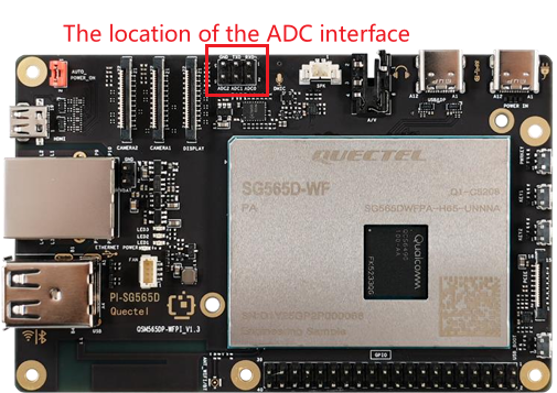
Hardware interface
The Quectel Pi H1 includes three ADC channels, with a maximum input voltage of 1.8 V.
Function usage
ADC input channel paths
The system nodes corresponding to the ADC channels are as follows:
/sys/bus/iio/devices/iio:device1/in_voltage_pm7325_adc0_input
/sys/bus/iio/devices/iio:device1/in_voltage_pm7325_adc1_input
/sys/bus/iio/devices/iio:device1/in_voltage_pm7325_adc2_input
Reading via terminal
You can directly read the raw register value of the corresponding channel in the terminal, for example:
cat /sys/bus/iio/devices/iio:device1/in_voltage_pm7325_adc0_input
The system returns an integer between 0 and 65,535, representing the raw sampling value from the PMIC's internal ADC. To convert the raw value to voltage, you can calculate it proportionally based on the ADC reference voltage (1.8 V):
V_input = (raw / 65535) × 1.8