
Specifications
Note: Unless otherwise specified, an asterisk ( * ) after a function, feature, interface, pin name, command, argument, and so on indicates that it is under development and currently not supported; and the asterisk ( * ) after a model indicates that the model sample is currently unavailable.
Specifications parameters
| Quectel Pi M1 | Description |
|---|---|
| Package | PCBA |
| Size (mm) | (85 ± 0.2) × (56 ± 0.2) × (21.66 ± 0.2) |
| Weight (g) | – |
Key parameters
| Category | Description |
|---|---|
| Application processor | Octa-core 64-bit ARM Kryo™ 260 processor: 4 × A73 @ 2.0 GHz, 1 MB L2 cache 4 × A53 @ 1.8 GHz, 512 KB L2 cache |
| GPU | 64-bit Adreno™ 610 @ 1050 MHz |
| Storage | 64 GB eMMC + 4 GB LPDDR4X |
| Operating system | Linux/Android/Ubuntu* |
| USB interface | 1 × USB 3.0 Type-C interface with a data transfer rate up to 5 Gbps, used for firmware flashing (requires shorting BOOT) and host mode communication 2 × Standard USB 3.0 Type-A interfaces, host mode only, data transfer rate up to 5 Gbps 2 × Standard USB 2.0 Type-A interfaces, host mode only, data transfer rate up to 480 Mbps 1 × USB Type-C interface, main power supply interface |
| SIM interface | 2 × (U)SIM interfaces, 1.8/2.95 V SIM cards, dual SIM dual standby (Nano SIM and eSIM) |
| Display interface | 1 × Micro HDMI interface, Micro HDMI 2.0 (frame rate*), encoding: 1080P (H.264/H.265) @ 60 fps*), decoding: 1080P (H.264/H.265/VP9) @ 60 fps*) 1 × FPC connector, based on MIPI standard FHD+ (1080 × 2520) @ 60 fps* |
| Audio interface | 1 × SH1.0-4P audio interface 1 × Micro HDMI interface, audio output 1 × MEMS microphone |
| Camera interface | 2 × FPC connectors, 4-lane MIPI CSI, speed up to 2.5 Gbps/lane |
| Ethernet interface | 1 × Standard RJ45 interface, 10/100/1000 Mbps Ethernet. Supports POE function |
| SD interface | 1 × SD 3.0, 4-bit SDIO |
| UART interface | 2.54 mm header (1 × 3 pins), debug use only |
| Expansion interfaces | 4 × I2C interfaces (multiplexed with other interfaces) 3 × SPI interfaces (multiplexed with other interfaces, master mode only) 4 × UART interfaces (multiplexed with other interfaces) 28 × GPIO interfaces (multiplexed with other interfaces) |
| Button interfaces | 1 × PWRKEY, internal pull-up |
| LED indicators | Blue and Green |
| Antenna interfaces | 1 x MAIN, main antenna 1 x DRX, diversity reception antenna 1 x GNSS, GNSS antenna 1 × Wi-Fi/BT, Wi-Fi and Bluetooth antenna |
| LTE | Compliant with 3GPP Rel-10 FDD and TDD |
| GNSS | GPS, GLONASS, BDS, Galileo, QZSS and SBAS positioning systems |
| WLAN | Operation modes: AP and STA Operating frequencies: 2.4 GHz, 5 GHz |
| Bluetooth | Bluetooth Core Specification Version 5.0 Classic Bluetooth and Low Energy Bluetooth (BLE) |
| Temperature range | Normal operating temperature: 0 ~ +70 °C Storage temperature: -40 ~ +90 °C |
| Power supply requirements | Powered via USB Type-C, recommended to use a 18 W power adapter supporting PD protocol |
| Shield cover | None |
| Firmware upgrade | USB0 OTA |
| RoHS | All components fully compliant with EU RoHS standards |
Note: The Micro HDMI and MIPI display interfaces are mutually exclusive and cannot be used simultaneously.
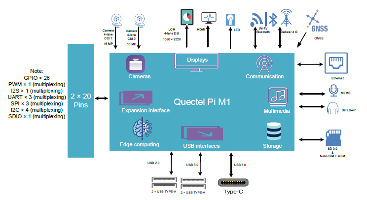
Functional block diagram
Interface description
Detailed interface diagram
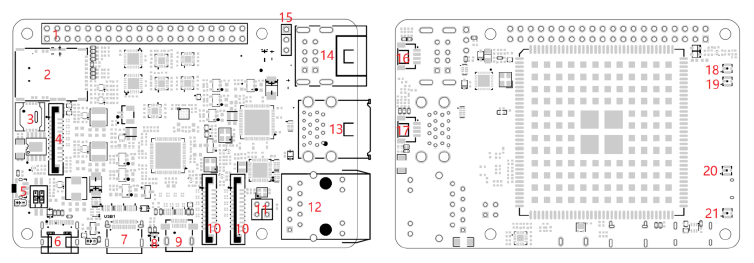
Interface description table
| No. | Interface name | Description |
|---|---|---|
| 1 | 2 × 20 Pin headers | GPIO with multiple multiplexing functions, can be multiplexed as I2C, SPI, etc. |
| 2 | SD card interface | SD + Nano SIM 2-in-1 socket, SD 3.0 protocol |
| 2 | (U)SIM card interface | SD + Nano SIM 2-in-1 socket, 1.8/2.95 V (U)SIM card |
| 3 | eSIM card interface | eSIM (MFF2) flip-lid socket, 1.8/2.95 V eSIM |
| 4 | DSI display interface | One channel 4-lane MIPI DSI, data rate up to 1.5 Gbps/lane, based on MIPI standard FHD+ (1080 × 2520) @ 60 fps* |
| 5 | PWRKEY button | Power on/off button |
| 6 | USB Type-C power | Provides DC power via USB Type-C, supports PD |
| 7 | USB Type-C | USB 3.0 Type-C interface |
| 8 | MEMS input | MEMS microphone |
| 9 | Micro HDMI interface | Micro HDMI video output interface, 1080P @ 60 Hz |
| 10 | Camera interface | Two channels 4-lane MIPI CSI, data rate up to 2.5 Gbps/lane |
| 11 | POE interface | 2 × 2 Pins headers, POE power output |
| 12 | Ethernet interface | 10/100/1000 Mbps Ethernet |
| 13 | USB Type-A 3.0 | Two standard USB 3.0 Type-A interfaces |
| 14 | USB Type-A 2.0 | Two standard USB 2.0 Type-A interfaces |
| 15 | DBG interface | 1 × 3 Pins header |
| 16 | ADC interface | SH1.0-4P interface, two-channel ADC input, input voltage range from 0 ~ 5.0 V |
| 17 | Audio in/out interface | SH1.0-4P interface, audio input/output |
| 18 | GNSS antenna interface | IPEX-4TH test connector |
| 19 | Diversity antenna interface | IPEX-4TH test connector |
| 20 | Main antenna interface | IPEX-4TH test connector |
| 21 | Wi-Fi/Bluetooth antenna interface | IPEX-4TH test connector |
| 22 | PWRKEY button | Power on/off button |
| 23 | USB Type-C power | Provides DC power via USB Type-C, supports PD |
| 24 | ADC interface | SH1.0-4P interface, two-channel ADC input, input voltage range from 0 ~ 5.0 V |
| 25 | POE interface | 2 × 2 Pins headers, POE power output |
| 26 | DBG interface | 1 × 3 Pins header |
40-pin connector definition
The following is the list of definitions for the 2 × 20-pin connector:
| Pin no. | Pin name | Pin no. | Pin name |
|---|---|---|---|
| 1 | VCC_3V3 | 2 | VCC_5V |
| 3 | GPIO_14 | 4 | VCC_5V |
| 5 | GPIO_15 | 6 | GND |
| 7 | GPIO_83 | 8 | GPIO_69 |
| 9 | GND | 10 | GPIO_70 |
| 11 | GPIO_106 | 12 | GPIO_98 |
| 13 | GPIO_31 | 14 | GND |
| 15 | GPIO_71 | 16 | GPIO_84 |
| 17 | VCC_3V3 | 18 | GPIO_25 |
| 19 | GPIO_1 | 20 | GND |
| 21 | GPIO_0 | 22 | GPIO_80 |
| 23 | GPIO_2 | 24 | GPIO_3 |
| 25 | GND | 26 | GPIO_82 |
| 27 | GPIO_109 | 28 | GPIO_110 |
| 29 | GPIO_5 | 30 | GND |
| 31 | GPIO_4 | 32 | GPIO_67 |
| 33 | GPIO8 | 34 | GND |
| 35 | GPIO_99 | 36 | GPIO_16 |
| 37 | GPIO_17 | 38 | GPIO_101 |
| 39 | GND | 40 | GPIO_100 |
Camera pin definitions
The following is the list of definitions for Camera 1 22-pin connector:
| Pin no. | Pin name | Pin no. | Pin name |
|---|---|---|---|
| 1 | GND | 2 | MIPI_CSI0_LN0N |
| 3 | MIPI_CSI0_LN0P | 4 | GND |
| 5 | MIPI_CSI0_LN1N | 6 | MIPI_CSI0_LN1P |
| 7 | GND | 8 | MIPI_CSI0_CLKN |
| 9 | MIPI_CSI0_CLKP | 10 | GND |
| 11 | MIPI_CSI0_LN2N | 12 | MIPI_CSI0_LN2P |
| 13 | GND | 14 | MIPI_CSI0_LN3N |
| 15 | MIPI_CSI0_LN3P | 16 | GND |
| 17 | CAM_PWDN_1 | 18 | CAM0_MCLK |
| 19 | GND | 20 | CAM_I2C_SCL0_0 |
| 21 | CAM_I2C_SDA0_0 | 22 | VDD_3V3_CAM1 |
The following is the list of definitions for Camera 2 22-pin connector:
| Pin no. | Pin name | Pin no. | Pin name |
|---|---|---|---|
| 1 | GND | 2 | MIPI_CSI0_LN0N |
| 3 | MIPI_CSI0_LN0P | 4 | GND |
| 5 | MIPI_CSI0_LN1N | 6 | MIPI_CSI0_LN1P |
| 7 | GND | 8 | MIPI_CSI0_CLKN |
| 9 | MIPI_CSI0_CLKP | 10 | GND |
| 11 | MIPI_CSI0_LN2N | 12 | MIPI_CSI0_LN2P |
| 13 | GND | 14 | MIPI_CSI0_LN3N |
| 15 | MIPI_CSI0_LN3P | 16 | GND |
| 17 | CAM_PWDN_1 | 18 | CAM0_MCLK |
| 19 | GND | 20 | CAM_I2C_SCL1_1 |
| 21 | CAM_I2C_SDA1_1 | 22 | VDD_3V3_CAM2 |
Display pin definitions
The following is the list of definitions for Display 22-pin connector:
| Pin no. | Pin name | Pin no. | Pin name |
|---|---|---|---|
| 1 | GND | 2 | MIPI_DSI_LN0N |
| 3 | MIPI_DSI_LN0P | 4 | GND |
| 5 | MIPI_DSI_LN1N | 6 | MIPI_DSI_LN1P |
| 7 | GND | 8 | MIPI_DSI_CLKN |
| 9 | MIPI_DSI_CLKP | 10 | GND |
| 11 | MIPI_DSI_LN2N | 12 | MIPI_DSI_LN2P |
| 13 | GND | 14 | MIPI_DSI_LN3N |
| 15 | MIPI_DSI_LN3P | 16 | GND |
| 17 | LCM_RST_1 | 18 | LCM_INT_1 |
| 19 | GND | 20 | TP_I2C_SCL1 |
| 21 | TP_I2C_SDA1 | 22 | VDD_3V3_LCM1 |
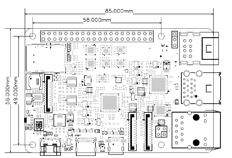
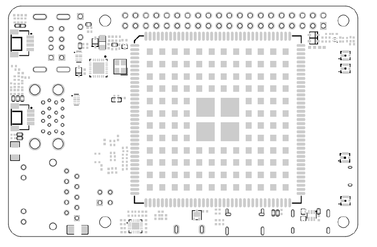
Mechanical dimensions
This section mainly introduces the mechanical dimensions of the product. All dimension units are in mm. For all dimensions without specified tolerances, the tolerance is +0.10/-0.15.
Electrical characteristics
Absolute maximum ratings
| Parameter | Minimum value | Maximum value | Unit |
|---|---|---|---|
| USB Type-C supply voltage | -0.3 | 20.0 | V |
| Digital pin voltage of expansion interface | -0.3 | 3.6 | V |
Note: Exceeding the operating conditions shown in the above table may cause permanent damage to the product.
Power supply ratings
The product can be powered through the POWER IN Type-C port, supporting USB PD 3.0 fast charging protocol. The power supply for the product should be able to provide 5 V/5 A or higher power supply.
Digital logic level characteristics
2 × 20-pin I/O requirements (Unit: V)
| Parameter | Description | Minimum value | Maximum value |
|---|---|---|---|
| VIH | Input high level | 2.81 | 3.30 |
| VIL | Input low level | 0 | 0.66 |
| VOH | Output high level | 3.00 | 3.30 |
| VOL | Output low level | 0 | 0.30 |
ESD protection
Static electricity generated by sources such as the human body and friction between microelectronics can discharge into the product through various pathways, potentially causing damage. Therefore, attention must be paid to ESD protection, and reasonable precautionary measures should be taken. For example: Wear anti-static gloves during R&D, production, assembly, and testing processes; during product design, add ESD protection components at circuit interfaces and other points vulnerable to electrostatic discharge. ESD withstand voltage (temperature: 25 ~ 30°C, humidity: 40 ± 5 %; unit: kV).
| Test point | Contact discharge | Air discharge |
|---|---|---|
| VBAT and GND | – | – |
| Other interfaces | – | – |
Operating and storage temperature
Operating and storage temperature (Unit: ℃)
| Parameter | Minimum value | Typical value | Maximum value |
|---|---|---|---|
| Normal operating temperature | 0 | +25 | +70 |
| Storage temperature | -30 | – | +90 |