
40‑Pin expansion
Quectel Pi M1 smart single-board computer provides a standard 40‑pin GPIO expansion header, supporting multiple peripheral interfaces such as GPIO, I2C, SPI, UART and PWM. This chapter describes how to test these interfaces.
Pin definition
GPIO test
This section uses pin7 of the 40‑pin header as an example to demonstrate how to use the GPIO function. The corresponding gpio_num for pin7 is 83.
Hardware connection
Method 1: Measure voltage with a multimeter
Connect pin7 (GPIO_83) to the positive probe of the multimeter, and pin6 (GND) to the negative probe. You can measure the output voltage of the pin with the multimeter to verify that the GPIO function works properly.
Method 2: Use a GPIO expansion board with LEDs
You can also plug a Raspberry Pi 4B/3B GPIO expansion board into the 40‑pin header to test GPIO high/low levels. This expansion board routes out each GPIO pin and attaches a corresponding indicator LED. Configure the GPIO pin under test as an output and connect it to the expansion board: when the GPIO outputs a high level the LED will turn on, and when it outputs a low level the LED will turn off. In this way you can visually check whether the GPIO level changes as expected.
For more information about this expansion board, refer to the GPIO terminal expansion board entry in the Supported Accessories chapter (see: Supported Accessories).
GPIO expansion board LED example
Test method
The following example is based on the Android platform. It directly uses the pre-compiled GPIO control executable file pin_control_sysfs (compiled via NDK) for testing, so there is no need to compile it yourself.
Download:
test_program/pin_control
- Push the executable to the board and grant execution permission:
adb push <local_path>/pin_control_sysfs /data/local/tmp/pin_control_sysfs
adb shell "chmod +x /data/local/tmp/pin_control_sysfs"
adb shell "ls -lh /data/local/tmp/pin_control_sysfs"
- Enter the device shell and run the tool to view usage:
adb shell
cd /data/local/tmp
./pin_control_sysfs
After running, it prints the available commands and the supported 40‑pin mappings. An example output is shown below:
Usage: ./pin_control_sysfs <pin_number|all> <up|down|get>
Example: ./pin_control_sysfs pin3 up     # drive pin3 high
Example: ./pin_control_sysfs pin5 down   # drive pin5 low
Example: ./pin_control_sysfs pin7 get    # read pin7
Example: ./pin_control_sysfs all up      # drive all pins high
Example: ./pin_control_sysfs all down    # drive all pins low
Example: ./pin_control_sysfs all get     # read status of all pins

Supported pins:
pin3 (GPIO494)  pin5 (GPIO495)  pin7 (GPIO481)  pin8 (GPIO467)
pin10(GPIO468)  pin11(GPIO504)  pin12(GPIO496)  pin13(GPIO429)
pin15(GPIO469)  pin16(GPIO482)  pin18(GPIO423)  pin19(GPIO399)
pin21(GPIO398)  pin22(GPIO478)  pin23(GPIO400)  pin24(GPIO401)
pin26(GPIO480)  pin27(GPIO412)  pin28(GPIO413)  pin29(GPIO403)
pin31(GPIO402)  pin32(GPIO465)  pin33(GPIO396)  pin35(GPIO497)
pin36(GPIO414)  pin37(GPIO415)  pin38(GPIO499)  pin40(GPIO498)
- Common operation examples:
- Drive a single pin high:
./pin_control_sysfs pin7 up - Drive a single pin low:
./pin_control_sysfs pin7 down - Read a single pin:
./pin_control_sysfs pin7 get - Operate on all pins:
./pin_control_sysfs all up | all down | all get
- Drive a single pin high:
Note: Make sure the target pin is not being used by other functions (such as I2C/SPI/UART) before running the test. It is recommended to verify whether the level changes as expected using the expansion board LEDs or a multimeter.
Click to expand/collapse: pin_control source code (can be built with NDK)
#include <stdio.h>
#include <stdlib.h>
#include <unistd.h>
#include <fcntl.h>
#include <string.h>
#include <errno.h>

// GPIO pin mapping table (SC200U Gamma Linux project)
typedef struct {
    int pin;
    int gpio_num;  // Linux sysfs GPIO number
} pin_map_t;

// Based on Bengal platform GPIO mapping (same as Android project)
static const pin_map_t pin_mapping[] = {
    {3, 494}, {5, 495}, {7, 481}, {8, 467}, {10, 468}, {11, 504}, {12, 496}, {13, 429},
    {15, 469}, {16, 482}, {18, 423}, {19, 399}, {21, 398}, {22, 478}, {23, 400}, {24, 401},
    {26, 480}, {27, 412}, {28, 413}, {29, 403}, {31, 402}, {32, 465}, {33, 396}, {35, 497},
    {36, 414}, {37, 415}, {38, 499}, {40, 498}
};

#define PIN_COUNT (sizeof(pin_mapping) / sizeof(pin_map_t))

/**
 * Get GPIO mapping info according to pin number
 */
const pin_map_t* get_pin_info(int pin) {
    for (int i = 0; i < PIN_COUNT; i++) {
        if (pin_mapping[i].pin == pin) {
            return &pin_mapping[i];
        }
    }
    return NULL;
}

/**
 * Export GPIO to sysfs
 */
int export_gpio(int gpio_num) {
    char path[64];
    int fd;

    // Check if the GPIO is already exported
    snprintf(path, sizeof(path), "/sys/class/gpio/gpio%d", gpio_num);
    if (access(path, F_OK) == 0) {
        return 0;  // Already exported
    }

    // Export GPIO
    fd = open("/sys/class/gpio/export", O_WRONLY);
    if (fd < 0) {
        printf("Failed to open /sys/class/gpio/export: %s\n", strerror(errno));
        return -1;
    }

    char gpio_str[8];
    snprintf(gpio_str, sizeof(gpio_str), "%d", gpio_num);
    if (write(fd, gpio_str, strlen(gpio_str)) < 0) {
        // If already exported, it returns an error, but this is not a fatal issue
        if (errno != EBUSY) {
            printf("Failed to export GPIO%d: %s\n", gpio_num, strerror(errno));
            close(fd);
            return -1;
        }
    }
    close(fd);

    usleep(100000);  // Wait 100ms for the sysfs node to be created
    return 0;
}

/**
 * Unexport the GPIO
 */
int unexport_gpio(int gpio_num) {
    int fd;

    fd = open("/sys/class/gpio/unexport", O_WRONLY);
    if (fd < 0) {
        return -1;
    }

    char gpio_str[8];
    snprintf(gpio_str, sizeof(gpio_str), "%d", gpio_num);
    write(fd, gpio_str, strlen(gpio_str));
    close(fd);

    return 0;
}

/**
 * Set GPIO direction
 */
int set_gpio_direction(int gpio_num, const char *direction) {
    char path[64];
    int fd;

    snprintf(path, sizeof(path), "/sys/class/gpio/gpio%d/direction", gpio_num);
    fd = open(path, O_WRONLY);
    if (fd < 0) {
        printf("Failed to open %s: %s\n", path, strerror(errno));
        return -1;
    }

    if (write(fd, direction, strlen(direction)) < 0) {
        printf("Failed to set direction for GPIO%d: %s\n", gpio_num, strerror(errno));
        close(fd);
        return -1;
    }
    close(fd);

    return 0;
}

/**
 * Set GPIO value
 */
int set_gpio_value(int gpio_num, int value) {
    char path[64];
    int fd;

    snprintf(path, sizeof(path), "/sys/class/gpio/gpio%d/value", gpio_num);
    fd = open(path, O_WRONLY);
    if (fd < 0) {
        printf("Failed to open %s: %s\n", path, strerror(errno));
        return -1;
    }

    char value_str[2];
    snprintf(value_str, sizeof(value_str), "%d", value);
    if (write(fd, value_str, 1) < 0) {
        printf("Failed to set value for GPIO%d: %s\n", gpio_num, strerror(errno));
        close(fd);
        return -1;
    }
    close(fd);

    return 0;
}

/**
 * Read GPIO value
 */
int get_gpio_value(int gpio_num, int *value) {
    char path[64];
    int fd;
    char val[2];

    snprintf(path, sizeof(path), "/sys/class/gpio/gpio%d/value", gpio_num);
    fd = open(path, O_RDONLY);
    if (fd < 0) {
        printf("Failed to open %s: %s\n", path, strerror(errno));
        return -1;
    }

    if (read(fd, val, 1) < 0) {
        printf("Failed to read GPIO%d: %s\n", gpio_num, strerror(errno));
        close(fd);
        return -1;
    }
    close(fd);

    *value = (val[0] == '1') ? 1 : 0;
    return 0;
}

/**
 * Control GPIO via sysfs
 * action: 0=drive low, 1=drive high, 2=read
 */
int control_gpio_sysfs(int gpio_num, int action) {
    // Ensure GPIO is exported
    if (export_gpio(gpio_num) < 0) {
        return -1;
    }

    if (action == 0 || action == 1) {
        // Set direction to output
        if (set_gpio_direction(gpio_num, "out") < 0) {
            return -1;
        }

        // Set value
        if (set_gpio_value(gpio_num, action) < 0) {
            return -1;
        }

        printf("✓ GPIO%d has been set to %s level\n", gpio_num, action ? "HIGH" : "LOW");

        // Verify whether the setting has taken effect
        usleep(50000);
        int verify_value;
        if (get_gpio_value(gpio_num, &verify_value) == 0) {
            printf("  Verify: GPIO%d actual state: %s level (value: %d)\n",
                   gpio_num, verify_value ? "HIGH" : "LOW", verify_value);
        }

    } else if (action == 2) {
        // Read GPIO value
        int value;
        if (get_gpio_value(gpio_num, &value) == 0) {
            printf("✓ GPIO%d current state: %s level (value: %d)\n",
                   gpio_num, value ? "HIGH" : "LOW", value);
        } else {
            return -1;
        }
    }

    return 0;
}

/**
 * Read status of all pins
 */
int read_all_pins() {
    printf("========================================\n");
    printf("=== Read status of all pins ===\n");
    printf("========================================\n");
    int success_count = 0;

    for (int i = 0; i < PIN_COUNT; i++) {
        printf("pin%d (GPIO%d): ", pin_mapping[i].pin, pin_mapping[i].gpio_num);
        fflush(stdout);

        if (control_gpio_sysfs(pin_mapping[i].gpio_num, 2) == 0) {
            success_count++;
        } else {
            printf("✗ read failed\n");
        }
    }

    printf("========================================\n");
    printf("Successfully read %d/%lu pins\n", success_count, PIN_COUNT);
    printf("========================================\n");
    return 0;
}

/**
 * Control all pins
 */
int control_all_pins(int action) {
    printf("========================================\n");
    printf("Start setting all pins to %s level...\n", action ? "HIGH" : "LOW");
    printf("========================================\n");
    int success_count = 0;

    for (int i = 0; i < PIN_COUNT; i++) {
        printf("pin%d (GPIO%d): ", pin_mapping[i].pin, pin_mapping[i].gpio_num);
        fflush(stdout);

        if (control_gpio_sysfs(pin_mapping[i].gpio_num, action) == 0) {
            success_count++;
        } else {
            printf("✗ control failed\n");
        }
    }

    printf("========================================\n");
    printf("Successfully controlled %d/%lu pins\n", success_count, PIN_COUNT);
    printf("========================================\n");

    return (success_count == PIN_COUNT) ? 0 : 1;
}

/**
 * Show help information
 */
void show_help(const char *prog_name) {
    printf("Usage: %s <pin_number|all> <up|down|get>\n", prog_name);
    printf("Example: %s pin3 up     # drive pin3 high\n", prog_name);
    printf("Example: %s pin5 down   # drive pin5 low\n", prog_name);
    printf("Example: %s pin7 get    # read pin7\n", prog_name);
    printf("Example: %s all up      # drive all pins high\n", prog_name);
    printf("Example: %s all down    # drive all pins low\n", prog_name);
    printf("Example: %s all get     # read status of all pins\n", prog_name);
    printf("\nSupported pins:\n");

    for (int i = 0; i < PIN_COUNT; i++) {
        printf("pin%d(GPIO%d)  ", pin_mapping[i].pin, pin_mapping[i].gpio_num);
        if ((i + 1) % 4 == 0) printf("\n");
    }
    printf("\n");
}

/**
 * Main function
 */
int main(int argc, char *argv[]) {
    if (argc < 3) {
        show_help(argv[0]);
        return 1;
    }

    char *pin_str = argv[1];
    char *action_str = argv[2];

    // Parse action argument
    int action;
    if (strcmp(action_str, "up") == 0) {
        action = 1;
    } else if (strcmp(action_str, "down") == 0) {
        action = 0;
    } else if (strcmp(action_str, "get") == 0) {
        action = 2;
    } else {
        printf("Error: action must be up, down or get\n");
        return 1;
    }

    // Handle "all" command
    if (strcmp(pin_str, "all") == 0) {
        if (action == 2) {
            return read_all_pins();
        } else {
            return control_all_pins(action);
        }
    }

    // Parse pin number
    int pin;
    if (sscanf(pin_str, "pin%d", &pin) != 1) {
        printf("Error: invalid pin format, please use pin3, pin5, etc.\n");
        return 1;
    }

    const pin_map_t *pin_info = get_pin_info(pin);
    if (pin_info == NULL) {
        printf("Error: unsupported pin pin%d\n", pin);
        return 1;
    }

    printf("Control pin%d (GPIO%d)...\n", pin, pin_info->gpio_num);
    return control_gpio_sysfs(pin_info->gpio_num, action);
}
I2C test
Pin3 and pin5 of the 40-pin header are configured as the I2C Data and Clock pins by default. To test the I2C interface, an external I2C device is required. Here, we use the Waveshare Environment Sensor Expansion Board. After connecting it to the 40-pin header, the corresponding device node is mapped to /dev/i2c2.
Test preparation
In this test we use the Waveshare Environment Sensor Expansion Board (BME280). Please connect it to the 40-pin header.
Hardware connection illustration:
Quectel Pi M1 with Environment Sensor Expansion Board Connected
Test method
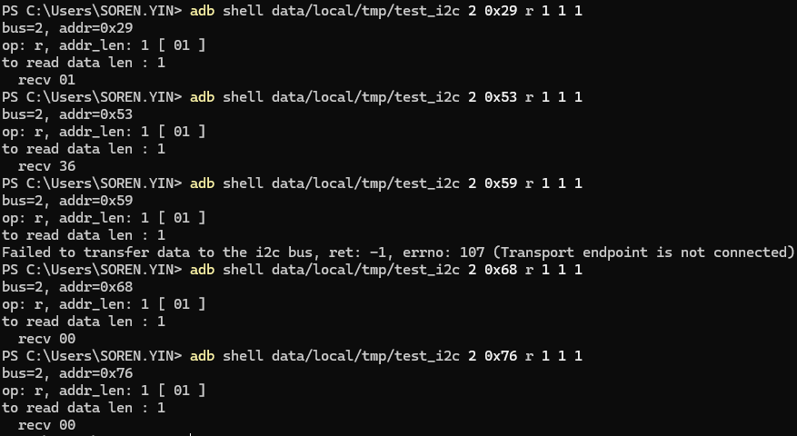
I2C test example output
Download:
test_program/test_i2c
Step 1: Push the tool and grant permission
adb root
adb push <local_path>/test_i2c /data/local/tmp/test_i2c
adb shell "chmod +x /data/local/tmp/test_i2c"
adb shell "ls -la /data/local/tmp/"
Step 2: Run the test
Example: On the i2c-2 bus, with the device address 0x29, read a 1-byte register address and 1 byte of data:
adb shell "data/local/tmp/test_i2c 2 0x29 r 1 1 1"
Step 3: Auxiliary checks
adb shell "i2cdetect -y -r 1"
adb shell "ls -al /dev/i2c*"
Log field description example
bus=1, addr=0x47: I2C bus 1, device address 0x47op: r, addr len: 1 [ 00 ]: Read operation, register address length 1 byte, register address 0x00to read data len : 2: Indicates 2 bytes of data are to be readrecv 12/recv 34: Actual data read is 0x12 and 0x34
Step 1: Create source file
Create a new file test_i2c.c with the following content:
Click to expand/collapse: test_i2c source code (can be built with NDK or cross‑compiler)
#include <stdio.h>
#include <stdlib.h>
#include <string.h>
#include <stdint.h>
#include <fcntl.h>
#include <errno.h>
#include <unistd.h>
#include <sys/ioctl.h>
#include <linux/i2c.h>
#include <linux/i2c-dev.h>

struct i2c_client {
    int bus;
    int addr;
    int fd;
};

static int is_sgm7220(const struct i2c_client *client) {
    return client->bus == 1 && client->addr == 0x47;
}

static int test_i2c_transfer(struct i2c_client *client, struct i2c_msg *msgs, int num)
{
    struct i2c_rdwr_ioctl_data msgset;
    int ret;

    msgset.msgs = msgs;
    msgset.nmsgs = num;

    ret = ioctl(client->fd, I2C_RDWR, &msgset);
    if (ret < 0) {
        printf("Failed to transfer data to the i2c bus, ret: %d, errno: %d (%s)\n", ret, errno, strerror(errno));
    }
    return ret;
}

static int test_i2c_write(struct i2c_client *client, uint8_t *buf, int data_len)
{
    struct i2c_msg msg_set[1] = {
        {
            .addr = client->addr,
            .flags = 0,
            .len = 2,
            .buf = (uint8_t *)buf
        }
    };

    if (is_sgm7220(client)) {
        msg_set[0].flags |= I2C_M_IGNORE_NAK;
    }

    return test_i2c_transfer(client, msg_set, 1);
}

static int test_i2c_read(struct i2c_client *client, uint8_t *buf, int addr_len, int data_len)
{
    struct i2c_msg msg_set[2] = {
        {
            .addr = client->addr,
            .flags = 0,
            .len = addr_len,
            .buf = buf
        },
        {
            .addr = client->addr,
            .flags = I2C_M_RD,
            .len = data_len,
            .buf = buf
        }
    };

    if (is_sgm7220(client)) {
        msg_set[0].flags |= I2C_M_REV_DIR_ADDR;
        msg_set[1].flags |= I2C_M_NOSTART;
    }

    return test_i2c_transfer(client, msg_set, 2);
}

int main(int argc, char *argv[]) {
    char filename[20];
    int i;
    struct i2c_client client;

    if (argc < 6) {
        printf("%s bus slave_addr r addr_len addr_array data_len\n", argv[0]);
        printf("%s bus slave_addr w data_len data_array\n", argv[0]);
        return -1;
    }
    client.bus = strtol(argv[1], NULL, 10);
    client.addr = strtol(argv[2], NULL, 16);

    printf("bus=%d, addr=0x%x\n", client.bus, client.addr);
    snprintf(filename, 19, "/dev/i2c-%d", client.bus);
    client.fd = open(filename, O_RDWR);
    if (client.fd < 0) {
        printf("Failed to open the i2c bus, errno: %d (%s)\n", errno, strerror(errno));
        return -1;
    }

    if (ioctl(client.fd, I2C_SLAVE_FORCE, client.addr) < 0) {
        printf("Failed to acquire bus access and/or talk to slave, errno: %d (%s)\n", errno, strerror(errno));
        close(client.fd);
        return -1;
    }

    i = 3;
    while (i < argc) {
        const char *op = argv[i++];
        uint8_t buf[128];
        int j, addr_len, data_len = 0;

        printf("op: %s, ", op);

        if (i >= argc) {
            printf("error i=%d, argc=%d\n", i, argc);
            goto _out;
        }
        data_len = strtol(argv[i++], NULL, 10);
        if (data_len <= 0 || data_len > sizeof(buf)) {
            printf(" error i=%d, argc=%d, data_len=%d\n", i, argc, data_len);
            goto _out;
        }

        printf("%s: %d [", strcmp(op, "r") == 0 ? "addr_len" : "data_len", data_len);
        for (j = 0; j < data_len; j++) {
            if (i >= argc) {
                printf(" error i=%d, argc=%d, j=%d\n", i, argc, j);
                goto _out;
            }
            buf[j] = strtol(argv[i++], NULL, 16);
            printf(" %02x", buf[j]);
        }
        printf(" ]\n");

        if (strcmp(op, "r") == 0) {
            addr_len = data_len;
            if (i >= argc) {
                printf(" error i=%d, argc=%d\n", i, argc);
                goto _out;
            }
            data_len = strtol(argv[i++], NULL, 10);
            printf("to read data len : %d\n", data_len);

            if (test_i2c_read(&client, buf, addr_len, data_len) <= 0) {
                break;
            }
            for (j = 0; j < data_len; j++) {
                printf("  recv %02x\n", buf[j]);
            }
        }
        else if (strcmp(op, "w") == 0) {
            printf("to write data len : %d\n", data_len);
            if (test_i2c_write(&client, buf, data_len) < 0) {
                break;
            }
        }
        else {
            printf("Invalid command %s\n", argv[i]);
            break;
        }
    }
_out:

    close(client.fd);

    return 0;
}
SPI test
On the 40‑pin header, the SPI function corresponds to chip‑select device nodes /dev/spidev0.0 and /dev/spidev0.1. You can check them with:
adb shell "ls /dev/spidev*"
Waveshare OLED Display Test (CS0 and CS1)
Wire the OLED according to the following table:
| OLED pin | Connect to | SC200U physical pin | Note |
|---|---|---|---|
| VCC | 3.3V power | Pin1 or Pin17 | Must be 3.3V |
| GND | Ground | Any GND such as Pin6/9/14 | Common ground |
| DIN/MOSI | SPI data | Pin19 | SPI_MOSI |
| CLK/SCK | SPI clock | Pin23 | SPI_CLK |
| CS/CE | Chip select | Pin24/Pin26 | SPI_CE0/SPI_CE1 |
| D/C | Data/command | Pin22 | GPIO80 |
| RES/RST | Reset | Pin18 | GPIO25 |
Hardware connection illustration:
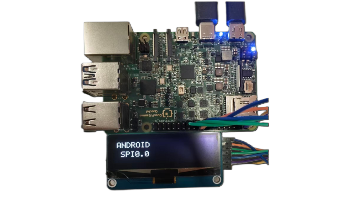
SPI0.0 (CE0, Pin24) test – OLED shows "ANDROID SPI0.0"
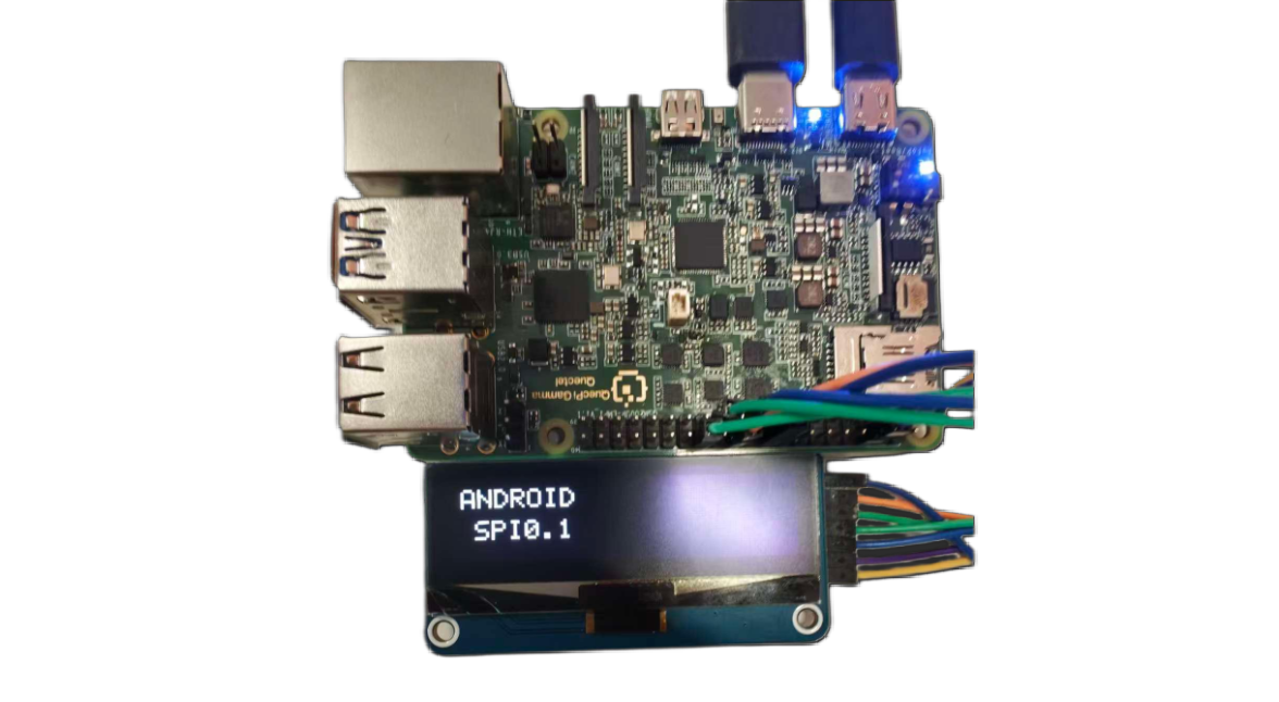
SPI0.1 (CE1, Pin26) test – OLED shows "ANDROID SPI0.1"
Download:
test_program/test_spi
Steps:
adb root
adb push "D:\tools\40pin android\test_android_spi" /data/local/tmp/test_android_spi
adb shell "chmod +x /data/local/tmp/test_android_spi"
adb shell
cd /data/local/tmp/
./test_android_spi
After the program starts, it will prompt you to select an SPI device:
- Choose 0: use
/dev/spidev0.0(CE0, Pin24) - Choose 1: use
/dev/spidev0.1(CE1, Pin26)
Select the corresponding device according to your wiring (if CS/CE is connected to pin24, choose 0; if connected to pin26, choose 1).
Test result:
After starting, the program performs the following tests in sequence:
╔══════════════════════════════════════════════════════╗
║        Android SPI OLED Test Program                ║
║        For Android devices                          ║
╚══════════════════════════════════════════════════════╝

Select SPI device:
  [0] /dev/spidev0.0 (CE0, Pin24)
  [1] /dev/spidev0.1 (CE1, Pin26)
  [c] Custom device path
Selection: 1

Using device: /dev/spidev0.1

Initializing GPIO...
  ✓ GPIO initialized successfully

Opening SPI device: /dev/spidev0.1
  ✓ SPI device opened and configured
    - Mode: 3
    - Speed: 2000000 Hz
    - Bits: 8 bits

Initialize OLED...
  Resetting OLED...
  Sending initialization commands...
  ✓ OLED initialization completed

━━━━━━━━━━━━━━━━━━━━━━━━━━━━━━━━━━━━━━━━━━━━━━
  Starting test sequence: SPI0.1
━━━━━━━━━━━━━━━━━━━━━━━━━━━━━━━━━━━━━━━━━━━━━━

[Test 1] Displaying device information...
  ✓ Screen should display: ANDROID SPI0.1

[Test 2] Full white screen test...
  ✓ Screen should be all white

[Test 3] Blink test (5 times)...
    Blink 1/5
    Blink 2/5
    Blink 3/5
    Blink 4/5
    Blink 5/5
  ✓ Blink test completed

[Test 4] FPS performance test...
  Running 100-frame update...
  ✓ Performance: 40.3 FPS (elapsed: 2.48s)
  ✓ FPS result displayed

[Test 5] Pattern test...
  Pattern 1: horizontal stripes
  Pattern 2: vertical stripes
  Pattern 3: checkerboard
  ✓ Pattern test completed

[Test 6] Test summary...
  ✓ Summary displayed
Test description:
- Test 1: verify that the OLED can display text correctly
- Test 2: verify OLED full‑screen display
- Test 3: verify OLED refresh function through blinking
- Test 4: test SPI communication performance (FPS value)
- Test 5: test various pattern displays
- Test 6: display the test summary
If all test items are marked with a √ , it indicates that the SPI bus communication and OLED function are working perfectly.
Step 1: Create source file
Create a new file test_spi.c with the following content:
Click to expand/collapse: test_spi source code (can be built with NDK or cross‑compiler)
/*
 * Test both CE0 and CE1 - requires manual wire switching
 * This helps verify which CS pin your OLED is connected to
 * Enhanced with text display and FPS performance test
 */

#include <stdio.h>
#include <stdlib.h>
#include <stdint.h>
#include <string.h>
#include <unistd.h>
#include <fcntl.h>
#include <sys/ioctl.h>
#include <linux/spi/spidev.h>
#include <time.h>

#define GPIO_BASE   398
#define GPIO_RST    (GPIO_BASE + 25)
#define GPIO_DC     (GPIO_BASE + 80)
#define SPI_MODE    SPI_MODE_3
#define SPI_SPEED   8000000

#define OLED_WIDTH  128
#define OLED_HEIGHT 32
#define OLED_PAGES  4

// Complete 5x7 font
static const uint8_t font_5x7[][5] = {
    {0x00, 0x00, 0x00, 0x00, 0x00}, // Space
    {0x3E, 0x51, 0x49, 0x45, 0x3E}, // 0
    {0x00, 0x42, 0x7F, 0x40, 0x00}, // 1
    {0x42, 0x61, 0x51, 0x49, 0x46}, // 2
    {0x21, 0x41, 0x45, 0x4B, 0x31}, // 3
    {0x18, 0x14, 0x12, 0x7F, 0x10}, // 4
    {0x27, 0x45, 0x45, 0x45, 0x39}, // 5
    {0x3C, 0x4A, 0x49, 0x49, 0x30}, // 6
    {0x01, 0x71, 0x09, 0x05, 0x03}, // 7
    {0x36, 0x49, 0x49, 0x49, 0x36}, // 8
    {0x06, 0x49, 0x49, 0x29, 0x1E}, // 9
    {0x7E, 0x11, 0x11, 0x11, 0x7E}, // A
    {0x7F, 0x49, 0x49, 0x49, 0x36}, {0x3E, 0x41, 0x41, 0x41, 0x22}, // B C
    {0x7F, 0x41, 0x41, 0x22, 0x1C}, {0x7F, 0x49, 0x49, 0x49, 0x41}, // D E
    {0x7F, 0x09, 0x09, 0x09, 0x01}, {0x3E, 0x41, 0x49, 0x49, 0x7A}, // F G
    {0x7F, 0x08, 0x08, 0x08, 0x7F}, {0x00, 0x41, 0x7F, 0x41, 0x00}, // H I
    {0x20, 0x40, 0x41, 0x3F, 0x01}, {0x7F, 0x08, 0x14, 0x22, 0x41}, // J K
    {0x7F, 0x40, 0x40, 0x40, 0x40}, {0x7F, 0x02, 0x0C, 0x02, 0x7F}, // L M
    {0x7F, 0x04, 0x08, 0x10, 0x7F}, {0x3E, 0x41, 0x41, 0x41, 0x3E}, // N O
    {0x7F, 0x09, 0x09, 0x09, 0x06}, {0x3E, 0x41, 0x51, 0x21, 0x5E}, // P Q
    {0x7F, 0x09, 0x19, 0x29, 0x46}, {0x46, 0x49, 0x49, 0x49, 0x31}, // R S
    {0x01, 0x01, 0x7F, 0x01, 0x01}, {0x3F, 0x40, 0x40, 0x40, 0x3F}, // T U
    {0x1F, 0x20, 0x40, 0x20, 0x1F}, {0x3F, 0x40, 0x38, 0x40, 0x3F}, // V W
    {0x63, 0x14, 0x08, 0x14, 0x63}, {0x07, 0x08, 0x70, 0x08, 0x07}, // X Y
    {0x61, 0x51, 0x49, 0x45, 0x43}, // Z
    {0x08, 0x08, 0x08, 0x08, 0x08}, // -
    {0x00, 0x36, 0x36, 0x00, 0x00}, // :
    {0x00, 0x60, 0x60, 0x00, 0x00}, // .
};

static int char_to_index(char c) {
    if (c == ' ') return 0;
    if (c >= '0' && c <= '9') return 1 + (c - '0');
    if (c >= 'A' && c <= 'Z') return 11 + (c - 'A');
    if (c >= 'a' && c <= 'z') return 11 + (c - 'a');
    if (c == '-') return 37;
    if (c == ':') return 38;
    if (c == '.') return 39;
    return 0;
}

int gpio_write(int gpio, int value);
void oled_quick_test(const char *device, const char *name);

int main() {
    printf("\n╔════════════════════════════════════════════════════════╗\n");
    printf("║  Chip Select Pin Comparison Tool                      ║\n");
    printf("╚════════════════════════════════════════════════════════╝\n");

    printf("\nThis tool helps identify which CS pin is connected.\n");
    printf("\nInstruction:\n");
    printf("  1. Connect OLED CS to Pin24 first\n");
    printf("  2. Run test - should see display\n");
    printf("  3. Move OLED CS to Pin26\n");
    printf("  4. Run test again - should see display\n");
    printf("\n");

    char choice;
    printf("Which pin is your OLED CS currently connected to?\n");
    printf("  [0] Pin24 (CE0)\n");
    printf("  [1] Pin26 (CE1)\n");
    printf("Choice: ");
    scanf(" %c", &choice);

    if (choice == '0') {
        printf("\nTesting CE0 (Pin24)...\n");
        oled_quick_test("/dev/spidev0.0", "CE0-PIN24");
    } else if (choice == '1') {
        printf("\nTesting CE1 (Pin26)...\n");
        oled_quick_test("/dev/spidev0.1", "CE1-PIN26");
    } else {
        printf("Invalid choice\n");
        return 1;
    }

    return 0;
}

void oled_quick_test(const char *device, const char *name) {
    // Display buffer
    static uint8_t buffer[OLED_PAGES][OLED_WIDTH];

    // Simple GPIO functions
    int gpio_export(int gpio) {
        int fd = open("/sys/class/gpio/export", O_WRONLY);
        if (fd < 0) return -1;
        char buf[10];
        snprintf(buf, sizeof(buf), "%d", gpio);
        write(fd, buf, strlen(buf));
        close(fd);
        usleep(100000);
        return 0;
    }

    int gpio_set_dir(int gpio) {
        char path[50];
        snprintf(path, sizeof(path), "/sys/class/gpio/gpio%d/direction", gpio);
        int fd = open(path, O_WRONLY);
        if (fd < 0) return -1;
        write(fd, "out", 3);
        close(fd);
        return 0;
    }

    int gpio_write(int gpio, int value) {
        char path[50];
        snprintf(path, sizeof(path), "/sys/class/gpio/gpio%d/value", gpio);
        int fd = open(path, O_WRONLY);
        if (fd < 0) return -1;
        char buf[2] = {value ? '1' : '0', 0};
        write(fd, buf, 1);
        close(fd);
        return 0;
    }

    void send_cmd(int fd, uint8_t cmd) {
        gpio_write(GPIO_DC, 0);
        write(fd, &cmd, 1);
        usleep(1000);
    }

    void set_pixel(int x, int y, int color) {
        if (x >= 0 && x < OLED_WIDTH && y >= 0 && y < OLED_HEIGHT) {
            int page = y / 8;
            int bit = y % 8;
            if (color)
                buffer[page][x] |= (1 << bit);
            else
                buffer[page][x] &= ~(1 << bit);
        }
    }

    void draw_char(int x, int y, char c) {
        int idx = char_to_index(c);
        for (int col = 0; col < 5; col++) {
            uint8_t data = font_5x7[idx][col];
            for (int row = 0; row < 8; row++) {
                if (data & (1 << row)) {
                    set_pixel(x + col, y + row, 1);
                }
            }
        }
    }

    void draw_text(int x, int y, const char *text) {
        int cursor = x;
        while (*text) {
            draw_char(cursor, y, *text);
            cursor += 6;
            text++;
        }
    }

    void clear_buffer() {
        memset(buffer, 0, OLED_PAGES * OLED_WIDTH);
    }

    void display_buffer(int fd) {
        for (int page = 0; page < OLED_PAGES; page++) {
            send_cmd(fd, 0xB0 + page);
            send_cmd(fd, 0x04);
            send_cmd(fd, 0x10);
            gpio_write(GPIO_DC, 1);
            write(fd, buffer[page], OLED_WIDTH);
        }
    }

    // Initialize GPIO
    gpio_export(GPIO_RST);
    gpio_export(GPIO_DC);
    usleep(200000);
    gpio_set_dir(GPIO_RST);
    gpio_set_dir(GPIO_DC);

    // Open SPI
    printf("  Opening %s...\n", device);
    int spi_fd = open(device, O_RDWR);
    if (spi_fd < 0) {
        perror("  ERROR: Cannot open device");
        printf("  → %s is NOT working or OLED not connected\n", name);
        return;
    }
    printf("  ✓ Device opened\n");

    // Configure SPI
    uint8_t mode = SPI_MODE;
    uint32_t speed = SPI_SPEED;
    ioctl(spi_fd, SPI_IOC_WR_MODE, &mode);
    ioctl(spi_fd, SPI_IOC_WR_MAX_SPEED_HZ, &speed);

    // Reset OLED
    printf("  Resetting OLED...\n");
    gpio_write(GPIO_RST, 0);
    usleep(50000);
    gpio_write(GPIO_RST, 1);
    usleep(50000);

    // Initialize OLED
    printf("  Initializing OLED...\n");
    send_cmd(spi_fd, 0xAE);
    send_cmd(spi_fd, 0x04); send_cmd(spi_fd, 0x10); send_cmd(spi_fd, 0x40);
    send_cmd(spi_fd, 0x81); send_cmd(spi_fd, 0xFF);
    send_cmd(spi_fd, 0xA1); send_cmd(spi_fd, 0xA6);
    send_cmd(spi_fd, 0xA8); send_cmd(spi_fd, 0x1F);
    send_cmd(spi_fd, 0xC8);
    send_cmd(spi_fd, 0xD3); send_cmd(spi_fd, 0x00);
    send_cmd(spi_fd, 0xD5); send_cmd(spi_fd, 0xF0);
    send_cmd(spi_fd, 0xD8); send_cmd(spi_fd, 0x05);
    send_cmd(spi_fd, 0xD9); send_cmd(spi_fd, 0xC2);
    send_cmd(spi_fd, 0xDA); send_cmd(spi_fd, 0x12);
    send_cmd(spi_fd, 0xDB); send_cmd(spi_fd, 0x08);
    send_cmd(spi_fd, 0xAF);
    printf("  ✓ OLED initialized\n");

    // Test 1: Display "USING: CE0" or "USING: CE1"
    printf("\n  [Test 1] Displaying chip select info...\n");
    clear_buffer();
    draw_text(10, 4, "USING:");
    if (strstr(name, "CE0")) {
        draw_text(25, 16, "CE0");
    } else {
        draw_text(25, 16, "CE1");
    }
    display_buffer(spi_fd);
    printf("  ✓ Screen showing: USING %s\n", strstr(name, "CE0") ? "CE0" : "CE1");
    sleep(3);

    // Test 2: Fill white
    printf("\n  [Test 2] Filling screen WHITE...\n");
    memset(buffer, 0xFF, OLED_PAGES * OLED_WIDTH);
    display_buffer(spi_fd);
    printf("  ✓ Screen should be WHITE\n");
    sleep(2);

    // Test 3: Blink test
    printf("\n  [Test 3] Blink test (5 times)...\n");
    for (int i = 0; i < 5; i++) {
        // White
        memset(buffer, 0xFF, OLED_PAGES * OLED_WIDTH);
        display_buffer(spi_fd);
        usleep(200000);

        // Black
        memset(buffer, 0x00, OLED_PAGES * OLED_WIDTH);
        display_buffer(spi_fd);
        usleep(200000);

        printf("    Blink %d/5\n", i + 1);
    }
    printf("  ✓ Blink test complete\n");

    // Test 4: FPS Performance Test
    printf("\n  [Test 4] FPS Performance Test...\n");
    printf("  Running 100 frame updates...\n");

    struct timespec start, end;
    clock_gettime(CLOCK_MONOTONIC, &start);

    for (int frame = 0; frame < 100; frame++) {
        // Generate test pattern
        for (int page = 0; page < OLED_PAGES; page++) {
            for (int x = 0; x < OLED_WIDTH; x++) {
                buffer[page][x] = (x + frame) & 0xFF;
            }
        }
        display_buffer(spi_fd);
    }

    clock_gettime(CLOCK_MONOTONIC, &end);
    double elapsed = (end.tv_sec - start.tv_sec) +
                     (end.tv_nsec - start.tv_nsec) / 1000000000.0;
    double fps = 100.0 / elapsed;

    printf("  ✓ Performance: %.1f FPS\n", fps);

    // Display FPS result on screen
    clear_buffer();
    draw_text(10, 4, "FPS TEST");
    char fps_str[20];
    snprintf(fps_str, sizeof(fps_str), "%.1f FPS", fps);
    draw_text(20, 16, fps_str);
    display_buffer(spi_fd);
    printf("  ✓ FPS result displayed on screen\n");
    sleep(3);

    // Test 5: CS Pin Functionality Test
    printf("\n  [Test 5] CS Pin Functionality Test...\n");
    printf("  This test verifies CS pin actually controls the device\n");

    // Step 1: Display number 1
    printf("  Step 1: Displaying pattern 1...\n");
    clear_buffer();
    draw_text(15, 4, "PATTERN");
    draw_text(50, 16, "1");
    display_buffer(spi_fd);
    sleep(2);

    // Step 2: Try to update through the OTHER CS (should fail if CS works)
    printf("  Step 2: Trying to update via OTHER CS...\n");
    const char *other_device = strstr(name, "CE0") ? "/dev/spidev0.1" : "/dev/spidev0.0";
    const char *other_name = strstr(name, "CE0") ? "CE1" : "CE0";

    int other_fd = open(other_device, O_RDWR);
    if (other_fd >= 0) {
        uint8_t mode = SPI_MODE;
        uint32_t speed = SPI_SPEED;
        ioctl(other_fd, SPI_IOC_WR_MODE, &mode);
        ioctl(other_fd, SPI_IOC_WR_MAX_SPEED_HZ, &speed);

        // Try to display pattern 2 via other CS
        clear_buffer();
        draw_text(15, 4, "PATTERN");
        draw_text(50, 16, "2");

        for (int page = 0; page < OLED_PAGES; page++) {
            send_cmd(other_fd, 0xB0 + page);
            send_cmd(other_fd, 0x04);
            send_cmd(other_fd, 0x10);
            gpio_write(GPIO_DC, 1);
            write(other_fd, buffer[page], OLED_WIDTH);
        }

        close(other_fd);
        printf("  Sent update via %s (other CS)\n", other_name);
        sleep(2);

        printf("\n  ╔════════════════════════════════════════════════╗\n");
        printf("  ║ CHECK SCREEN: Still showing '1' or changed to '2'? ║\n");
        printf("  ╚════════════════════════════════════════════════╝\n");
        printf("\n  If still showing '1': CS pin is WORKING correctly ✓\n");
        printf("  If changed to '2': CS pin NOT working (both CS active) ✗\n\n");
        sleep(2);
    }

    // Step 3: Update back via correct CS
    printf("  Step 3: Updating via correct CS (%s)...\n", name);
    clear_buffer();
    draw_text(15, 4, "BACK TO");
    draw_text(50, 16, "1");
    display_buffer(spi_fd);
    printf("  ✓ Should see pattern 1 again\n");
    sleep(2);

    // Test 6: FPS result summary
    printf("\n  [Test 6] Final Summary...\n");
    clear_buffer();
    draw_text(30, 4, name);
    char summary_str[20];
    snprintf(summary_str, sizeof(summary_str), "%.1fFPS", fps);
    draw_text(20, 16, summary_str);
    display_buffer(spi_fd);
    printf("  ✓ Summary displayed\n");
    sleep(3);

    // Clear screen
    clear_buffer();
    display_buffer(spi_fd);

    close(spi_fd);

    printf("\n======================================================================\n");
    printf("  %s Test Complete!\n", name);
    printf("======================================================================\n");
    printf("  CS Pin Test Result:\n");
    printf("    If screen didn't change to '2' in Step 2:\n");
    printf("      → CS pin is working correctly ✓\n");
    printf("    If screen changed to '2':\n");
    printf("      → CS pin might not be controlling the device ✗\n");
    printf("      → Both CS pins may be active simultaneously\n");
    printf("\n  Performance: %.1f FPS\n", fps);
    printf("======================================================================\n");
}
UART test
On the 40‑pin header, pin8 and pin10 are configured as UART by default, corresponding to device node /dev/ttyHS0.
You can list all serial devices in the system using the following command:
ls /dev/tty*
UART loopback test
In this test, pin8 and pin10 are shorted together to verify UART TX/RX functionality.
Hardware connection: Short pin8 (TX) and pin10 (RX) on the 40‑pin header.
Step 1: Create source file
Create a new file uart_loopback.c with the following content:
Click to expand/collapse: uart_loopback source code (can be built with NDK or cross‑compiler)
Example prebuilt executable: uart_loopback
#include <stdio.h>
#include <stdlib.h>
#include <string.h>
#include <unistd.h>
#include <fcntl.h>
#include <termios.h>
#include <errno.h>
#include <signal.h>

// Global variables for signal handling
static int serial_fd = -1;
static volatile int running = 1;

// Signal handler funtion
void signal_handler(int sig) {
    printf("\nUser interrupted test\n");
    running = 0;
    if (serial_fd >= 0) {
        close(serial_fd);
        printf("Serial port closed\n");
    }
    exit(0);
}

// Configure serial port parameters
int configure_serial(int fd, int baudrate) {
    struct termios tty;

    if (tcgetattr(fd, &tty) != 0) {
        printf("Failed to get serial attributes: %s\n", strerror(errno));
        return -1;
    }

    // Set baud rate
    speed_t speed;
    switch (baudrate) {
        case 9600:   speed = B9600;   break;
        case 19200:  speed = B19200;  break;
        case 38400:  speed = B38400;  break;
        case 57600:  speed = B57600;  break;
        case 115200: speed = B115200; break;
        case 230400: speed = B230400; break;
        default:     speed = B115200; break;
    }

    cfsetospeed(&tty, speed);
    cfsetispeed(&tty, speed);

    // Configure serial port parameters
    tty.c_cflag &= ~PARENB;        // No parity
    tty.c_cflag &= ~CSTOPB;        // 1 stop bit
    tty.c_cflag &= ~CSIZE;         // Clear data bits setting
    tty.c_cflag |= CS8;            // 8 data bits
    tty.c_cflag &= ~CRTSCTS;       // Disable HW flow control
    tty.c_cflag |= CREAD | CLOCAL; // Enable receiver and ignore modem control lines

    // Configure input mode
    tty.c_iflag &= ~(IXON | IXOFF | IXANY); // Disable SW flow control
    tty.c_iflag &= ~(ICANON | ECHO | ECHOE | ISIG); // Raw mode

    // Configure output mode
    tty.c_oflag &= ~OPOST; // Raw output

    // Configure local mode
    tty.c_lflag &= ~(ICANON | ECHO | ECHOE | ISIG); // Raw mode

    // Set timeout
    tty.c_cc[VTIME] = 10; // 1 second timeout
    tty.c_cc[VMIN] = 0;   // Non‑blocking read

    if (tcsetattr(fd, TCSANOW, &tty) != 0) {
        printf("Failed to set serial attributes: %s\n", strerror(errno));
        return -1;
    }

    return 0;
}

// UART loopback test function
int serial_loopback_test(const char* port, int baudrate) {
    char test_data[] = "Hello, Serial Loopback!";
    char received_data[256];
    ssize_t bytes_written, bytes_read;

    // Open serial port device
    serial_fd = open(port, O_RDWR | O_NOCTTY | O_SYNC);
    if (serial_fd < 0) {
        printf("Failed to open serial %s: %s\n", port, strerror(errno));
        return -1;
    }

    // Configure serial port
    if (configure_serial(serial_fd, baudrate) != 0) {
        close(serial_fd);
        return -1;
    }

    printf("Serial %s opened, start loopback test (press Ctrl+C to exit)...\n", port);

    while (running) {
        // Flush receive buffer
        tcflush(serial_fd, TCIOFLUSH);

        // Send data
        bytes_written = write(serial_fd, test_data, strlen(test_data));
        if (bytes_written < 0) {
            printf("Failed to send data: %s\n", strerror(errno));
            break;
        }
        printf("Send: %s\n", test_data);

        // Wait for data reception
        usleep(100000); // 100ms

        // Read loopback data
        bytes_read = read(serial_fd, received_data, sizeof(received_data) - 1);
        if (bytes_read < 0) {
            printf("Failed to read data: %s\n", strerror(errno));
            break;
        }

        received_data[bytes_read] = '\0'; // Add null terminator

        // Verify result
        if (bytes_read == strlen(test_data) &&
            strncmp(received_data, test_data, strlen(test_data)) == 0) {
            printf("Recv: %s → PASS\n\n", received_data);
        } else {
            printf("Receive mismatch: sent[%zu] vs recv[%zd] → FAIL\n",
                   strlen(test_data), bytes_read);
            if (bytes_read > 0) {
                printf("Received content: %s\n\n", received_data);
            } else {
                printf("No data received\n\n");
            }
        }

        sleep(1); // Repeat test at 1-second intervals
    }

    close(serial_fd);
    printf("Serial %s closed\n", port);
    return 0;
}

int main(int argc, char* argv[]) {
    const char* port = "/dev/ttyHS0";  // Default port
    int baudrate = 115200;            // Default baud rate

    // Parse command-line arguments
    if (argc >= 2) {
        port = argv[1];
    }
    if (argc >= 3) {
        baudrate = atoi(argv[2]);
    }

    // Set signal handlers
    signal(SIGINT, signal_handler);
    signal(SIGTERM, signal_handler);

    printf("UART loopback test program\n");
    printf("Serial port: %s\n", port);
    printf("Baudrate: %d\n", baudrate);
    printf("=====================================\n");

    // Run loopback test
    int result = serial_loopback_test(port, baudrate);

    return result;
}
Steps:
adb root
adb push <local_path>/uart_loopback_test /data/local/tmp/uart_loopback
adb shell chmod +x /data/local/tmp/uart_loopback
adb shell ls -la /data/local/tmp/
adb shell
cd /data/local/tmp/
./uart_loopback
Test result:
When pin8 and pin10 are shorted correctly, the program will continuously transmit data and verify if the received data matches the transmitted data::
UART loopback test program
Serial port: /dev/ttyHS0
Baudrate: 115200
=====================================
Serial port /dev/ttyHS0 opened, starting loopback test (press Ctrl+C to exit)...
Send: Hello, Serial Loopback!
Recv: Hello, Serial Loopback! → PASS

Send: Hello, Serial Loopback!
Recv: Hello, Serial Loopback! → PASS

Send: Hello, Serial Loopback!
Recv: Hello, Serial Loopback! → PASS
Press Ctrl+C to exit the test program. It will close the serial port and exit automatically.