

 English
Peripheral Interface Development Guide
Introduction
Quectel FCM242D and FGM842D series modules support QuecOpen® solution. QuecOpen® is an embedded development platform based on RTOS system. It is intended to simplify the design and development of IoT applications. For more information on QuecOpen®, see Quick_Start_Guide.
This document is applicable to QuecOpen® solution based on SDK build environment. It outlines how to use GPIO, UART, SPI, ADC, PWM and I2C APIs supported by the modules to develop corresponding peripheral interfaces.
GPIO API
Header File
ql_gpio.h, the header file of GPIO API, is in the ql_components\api\ directory. Unless otherwise specified, all GPIO header files mentioned in this document are in this directory.
API Description
ql_gpio_init
This function initializes a GPIO pin.
- Prototype
ql_gpio_errcode_e ql_gpio_init(ql_gpio_num_e gpio_num, ql_gpio_mode_e mode, ql_gpio_level_e level);
- Parameters
gpio_num: [In] GPIO pin number. See ql_gpio_num_e for details.mode: [In] GPIO mode. See ql_gpio_mode_e for details.level: [In] GPIO output level. It is valid only whenmodeisQL_GMODE_OUTPUT. See ql_gpio_level_e for details.
- Return Value
Result code. See ql_gpio_errcode_e for details.
ql_gpio_num_e
The enumeration of GPIO pin numbers:
typedef enum {
    QL_GPIO0 = 0,
    QL_GPIO1,
    QL_GPIO6 = 6,
    QL_GPIO7,
    QL_GPIO8,
    QL_GPIO9,
    QL_GPIO10,
    QL_GPIO11,
    QL_GPIO14 = 14,
    QL_GPIO15,
    QL_GPIO16,
    QL_GPIO17,
    QL_GPIO20 = 20,
    QL_GPIO21,
    QL_GPIO22,
    QL_GPIO23,
    QL_GPIO24,
    QL_GPIO26 = 26,
    QL_GPIO28 = 28,
} ql_gpio_num_e
| Member | Description |
|---|---|
| QL_GPIO0 | GPIO0 |
| QL_GPIO1 | GPIO1 |
| QL_GPIO6 | GPIO6 |
| QL_GPIO7 | GPIO7 |
| QL_GPIO8 | GPIO8 |
| QL_GPIO9 | GPIO9 |
| QL_GPIO10 | GPIO10 |
| QL_GPIO11 | GPIO11 |
| QL_GPIO14 | GPIO14 |
| QL_GPIO15 | GPIO15 |
| QL_GPIO16 | GPIO16 |
| QL_GPIO17 | GPIO17 |
| QL_GPIO20 | GPIO20 |
| QL_GPIO21 | GPIO21 |
| QL_GPIO22 | GPIO22 |
| QL_GPIO23 | GPIO23 |
| QL_GPIO24 | GPIO24 |
| QL_GPIO26 | GPIO26 |
| QL_GPIO28 | GPIO28 |
ql_gpio_mode_e
The enumeration of GPIO modes:
| Member | Description |
|---|---|
| QL_GMODE_HIGH_IMPEDANCE | High impedance |
| QL_GMODE_INPUT | Input is configured as floating |
| QL_GMODE_IN_PD | Input is configured with pull-down |
| QL_GMODE_IN_PU | Input is configured with pull-up |
| QL_GMODE_OUTPUT | Output |
ql_gpio_errcode_e
The enumeration of GPIO API result codes:
typedef enum {
    QL_GPIO_SUCCESS = 0,
    QL_GPIO_EXECUTE_ERR,
    QL_GPIO_INVALID_PARAM_ERR,
} ql_gpio_errcode_e;
- Members
| Member | Description |
|---|---|
| QL_GPIO_SUCCESS | Successful execution |
| QL_GPIO_EXECUTE_ERR | Failed execution |
| QL_GPIO_INVALID_PARAM_ERR | Invalid parameter |
ql_gpio_deinit
This function deinitializes the GPIO.
- Prototype
ql_gpio_errcode_e ql_gpio_deinit(ql_gpio_num_e gpio_num);
- Parameters
gpio_num: [In] GPIO pin number. See ql_gpio_num_e for details.
- Return Value
Result code. See ql_gpio_errcode_e for details.
ql_gpio_set_level
This function sets the level of the specified GPIO pin. It is valid only for output pins.
- Prototype
ql_gpio_errcode_e ql_gpio_set_level(ql_gpio_num_e gpio_num, ql_gpio_level_e level);
- Parameters
gpio_num: [In] GPIO pin number. See ql_gpio_num_e for details.level: [In] GPIO output level. See ql_gpio_level_e for details.
- Return Value
Result code. See ql_gpio_errcode_e for details.
ql_gpio_level_e
The enumeration of GPIO output levels:
typedef enum {
    QL_GPIO_LEVEL_LOW = 0,
    QL_GPIO_LEVEL_HIGH,
} ql_gpio_level_e;
- Members
| Member | Description |
|---|---|
| QL_GPIO_LEVEL_LOW | Low level |
| QL_GPIO_LEVEL_HIGH | High level |
ql_gpio_set_level_reverse
This function reverses the GPIO output level. It is valid only for output pins.
- Prototype
ql_gpio_errcode_e ql_gpio_set_level_reverse(ql_gpio_num_e gpio_num);
- Parameters
gpio_num: [In] GPIO pin number. See ql_gpio_num_e for details.
- Return Value
Result code. See ql_gpio_errcode_e for details.
ql_gpio_get_level
This function gets the level of the specified GPIO pin. It is valid only for input pins.
- Prototype
ql_gpio_errcode_e ql_gpio_get_level(ql_gpio_num_e gpio_num, uint32 *input_level);
- Parameters
gpio_num: [In] GPIO pin number. See ql_gpio_num_e for details.input_level: [Out] GPIO pin level.
- Return Value
Result code. See ql_gpio_errcode_e for details.
ql_gpio_int_init
This function initializes and enables the GPIO interrupt.
- Prototype
ql_gpio_errcode_e ql_gpio_int_init(ql_gpio_num_e gpio_num, ql_gpio_irq_trigger_e irq_trigger, ql_gpio_irq_callback cb);
- Parameters
gpio_num: [In] GPIO pin number. See ql_gpio_num_e for details.irq_trigger: [In] GPIO interrupt triggering mode. See ql_gpio_irq_trigger_e for details.cb: [In] GPIO interrupt callback function. See ql_gpio_irq_callback for details.
- Return Value
Result code. See ql_gpio_errcode_e for details.
ql_gpio_irq_trigger_e
The enumeration of GPIO interrupt triggering modes:
typedef enum {
    QL_IRQ_TRIGGER_LOW_LEVEL,
    QL_IRQ_TRIGGER_HIGH_LEVEL,
    QL_IRQ_TRIGGER_RISING_EDGE,
    QL_IRQ_TRIGGER_FALLING_EDGE,
} ql_gpio_irq_trigger_e;
- Members
| Member | Description |
|---|---|
| QL_IRQ_TRIGGER_LOW_LEVEL | GPIO interrupt triggered at low level |
| QL_IRQ_TRIGGER_HIGH_LEVEL | GPIO interrupt triggered at high level |
| QL_IRQ_TRIGGER_RISING_EDGE | GPIO interrupt triggered at rising edge |
| QL_IRQ_TRIGGER_FALLING_EDGE | GPIO interrupt triggered at falling edge |
ql_gpio_irq_callback
This is the callback function of GPIO interrupt.
- Prototype
typedef void (*ql_gpio_irq_callback)(void *arg);
- Parameters
arg: [In] Pin for triggering the GPIO interrupt.
- Return Value
None.
ql_gpio_int_disable
This function disables the configured GPIO interrupt.
- Prototype
ql_gpio_errcode_e ql_gpio_int_disable(ql_gpio_num_e gpio_num);
- Parameters
gpio_num: [In] GPIO pin number. See ql_gpio_num_e for details.
- Return Value
Result code. See ql_gpio_errcode_e for details.
GPIO Development Process
This chapter explains how to use the above GPIO API to configure GPIO and perform basic debugging.
GPIO Operation
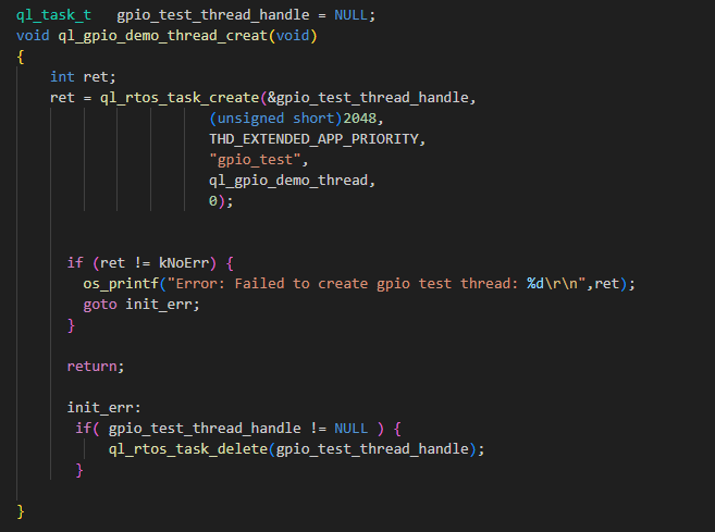
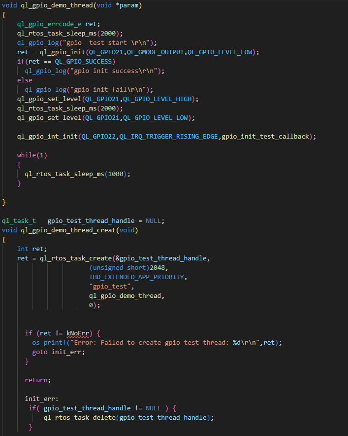
The example of how to use the GPIO API is provided in the ql_application/example/gpio_demo/ql_gpio_demo.c file in the module SDK. The descriptions of related functions are as follows:
ql_gpio_demo_thread_creat(): This function creates a GPIO task. Call this function to run the demo.ql_gpio_demo_thread(): This function executes the GPIO task. It initializes GPIO pins, configures output levels, and initiates, enables and disables GPIO interrupts.
To run the demo, set the CFG_ENABLE_QUECTEL_GPIO macro definition in ql_application/ql_app_main.c of SDK to 1 (i.e., to enable the macro definition). This will automatically trigger the execution of ql_gpio_demo_thread_creat() to create a test task.
For details on RTOS functions mentioned in the figures, see RTOS Development Guide.
Function Debugging
To debug the GPIO function, use the development board (e.g., FCM242D TE-B) with the module and follow these steps:
- Run the GPIO demo as explained in GPIO Operation.
- Recompile the firmware version and flash it to the module.
- Reboot the module.
- Open UART2 port and obtain log via this port.
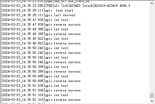
Pull up the GPIO22 pin level and verify that the GPIO9 pin level is reversed. This indicates that the GPIO interrupt has been triggered. The log information will be displayed as follows:
UART API
Header File
ql_uart.h, the header file of UART API, is in the ql_components\api\ directory. Unless otherwise specified, all header files mentioned in this document are in this directory.
API Description
ql_uart_set_dcbconfig
This function sets the UART port properties, which take effect after the UART port is reopened. Please note that the system log port cannot be used as the UART port.
- Prototype
ql_uart_errcode_e ql_uart_set_dcbconfig(ql_uart_port_number_e port, ql_uart_config_s *dcb);
- Parameters
port: [In] UART port number. See ql_uart_port_number_e for details.dcb: [In] Configuration of UART port properties. See ql_uart_config_s for details.
- Return Value
Result code. See ql_uart_errcode_e for details.
ql_uart_port_number_e
The enumeration of UART port numbers. Currently only two UART ports are supported.
typedef enum {
    QL_UART_PORT_1,
    QL_UART_PORT_2,
} ql_uart_port_number_e;
- Members
| Member | Description |
|---|---|
| QL_UART_PORT_1 | UART 1 |
| QL_UART_PORT_2 | UART 2 |
ql_uart_config_s
The structure of the configuration of UART port properties:
typedef struct {
    ql_uart_baud_e baudrate;
    ql_uart_databit_e data_bit;
    ql_uart_stopbit_e stop_bit;
    ql_uart_paritybit_e parity_bit;
    ql_uart_flowctrl_e flow_ctrl;
} ql_uart_config_s;
- Members
| Type | Parameter | Description |
|---|---|---|
ql_uart_baud_e |
baudrate | Baud rate. Default: 115200 bps. See ql_uart_baud_e for details. |
ql_uart_databit_e |
data_bit | Data bit. Default: 8 bits. See ql_uart_databit_e for details. |
ql_uart_stopbit_e |
stop_bit | Stop bit. Default: 1 bit. See ql_uart_stopbit_e for details. |
ql_uart_paritybit_e |
parity_bit | Parity bit. Default: No parity bit. See ql_uart_paritybit_e for details. |
ql_uart_flowctrl_e |
flow_ctrl | Flow control. Default: Disabled. See ql_uart_flowctrl_e for details. |
ql_uart_baud_e
The enumeration of baud rates:
typedef enum {
    QL_UART_BAUD_1200 = 1200,
    QL_UART_BAUD_2400 = 2400,
    QL_UART_BAUD_4800 = 4800,
    QL_UART_BAUD_9600 = 9600,
    QL_UART_BAUD_14400 = 14400,
    QL_UART_BAUD_19200 = 19200,
    QL_UART_BAUD_28800 = 28800,
    QL_UART_BAUD_33600 = 33600,
    QL_UART_BAUD_38400 = 38400,
    QL_UART_BAUD_57600 = 57600,
    QL_UART_BAUD_115200 = 115200,
    QL_UART_BAUD_230400 = 230400,
    QL_UART_BAUD_460800 = 460800,
    QL_UART_BAUD_921600 = 921600,
    QL_UART_BAUD_1000000 = 1000000,
    QL_UART_BAUD_2000000 = 2000000,
} ql_uart_baud_e
- Members
| Member | Description |
|---|---|
| QL_UART_BAUD_1200 | 1200 bps |
| QL_UART_BAUD_2400 | 2400 bps |
| QL_UART_BAUD_4800 | 4800 bps |
| QL_UART_BAUD_9600 | 9600 bps |
| QL_UART_BAUD_14400 | 14400 bps |
| QL_UART_BAUD_19200 | 19200 bps |
| QL_UART_BAUD_28800 | 28800 bps |
| QL_UART_BAUD_33600 | 33600 bps |
| QL_UART_BAUD_38400 | 38400 bps |
| QL_UART_BAUD_57600 | 57600 bps |
| QL_UART_BAUD_115200 | 115200 bps |
| QL_UART_BAUD_230400 | 230400 bps |
| QL_UART_BAUD_460800 | 460800 bps |
| QL_UART_BAUD_921600 | 921600 bps |
| QL_UART_BAUD_1000000 | 1000000 bps |
| QL_UART_BAUD_2000000 | 2000000 bps |
ql_uart_databit_e
The enumeration of data bits:
typedef enum {
    QL_UART_DATABIT_5,
    QL_UART_DATABIT_6,
    QL_UART_DATABIT_7,
    QL_UART_DATABIT_8,
} ql_uart_databit_e;
- Members
| Member | Description |
|---|---|
| QL_UART_DATABIT_5 | 5 bits |
| QL_UART_DATABIT_6 | 6 bits |
| QL_UART_DATABIT_7 | 7 bits |
| QL_UART_DATABIT_8 | 8 bits |
ql_uart_stopbit_e
The enumeration of stop bits:
typedef enum {
    QL_UART_STOP_1 = 0,
    QL_UART_STOP_2,
} ql_uart_stopbit_e;
- Members
| Member | Description |
|---|---|
| QL_UART_STOP_1 | 1 bit |
| QL_UART_STOP_2 | 2 bits |
ql_uart_paritybit_e
The enumeration of parity bits:
typedef enum {
    QL_UART_PARITY_NONE,
    QL_UART_PARITY_ODD,
    QL_UART_PARITY_EVEN,
} ql_uart_paritybit_e;
- Members
| Member | Description |
|---|---|
| QL_UART_PARITY_NONE | No parity |
| QL_UART_PARITY_ODD | Odd parity |
| QL_UART_PARITY_EVEN | Even parity |
ql_uart_flowctrl_e
The enumeration of flow control:
typedef enum {
    QL_FC_NONE = 0,
    QL_FC_HW_CTS,
    QL_FC_HW_RTS,
    QL_FC_HW_RTS_CTS,
} ql_uart_flowctrl_e;
- Members
| Member | Description |
|---|---|
| QL_FC_NONE | No flow control |
| QL_FC_HW_CTS | Hardware CTS |
| QL_FC_HW_RTS | Hardware RTS |
| QL_FC_HW_RTS_CTS | Hardware CTS and RTS |
ql_uart_errcode_e
The enumeration of UART API result codes:
typedef enum {
    QL_UART_SUCCESS = 0,
    QL_UART_EXECUTE_ERR,
    QL_UART_MEM_ADDR_NULL_ERR,
    QL_UART_INVALID_PARAM_ERR,
    QL_UART_NOT_OPEN_ERR,
} ql_uart_errcode_e;
- Members
| Member | Description |
|---|---|
| QL_UART_SUCCESS | Successful execution |
| QL_UART_EXECUTE_ERR | Failed execution |
| QL_UART_MEM_ADDR_NULL_ERR | Parameter address: Null |
| QL_UART_INVALID_PARAM_ERR | Invalid parameter |
| QL_UART_NOT_OPEN_ERR | UART port is not open |
ql_uart_get_dcbconfig
This function gets the configuration of UART port properties.
- Prototype
ql_uart_errcode_e ql_uart_get_dcbconfig(ql_uart_port_number_e port, ql_uart_config_s *dcb);
- Parameters
port: [In] UART port number. See ql_uart_port_number_e for details.dcb: [In] Configuration of UART port properties. See ql_uart_config_s for details.
- Return Value
Result code. See ql_uart_errcode_e for details.
ql_uart_open
This function opens the UART port.
- Prototype
ql_uart_errcode_e ql_uart_open(ql_uart_port_number_e port);
- Parameters
port: [In] UART port number. See ql_uart_port_number_e for details.
- Return Value
Result code. See ql_uart_errcode_e for details.
ql_uart_close
This function closes the UART port.
- Prototype
ql_uart_errcode_e ql_uart_close(ql_uart_port_number_e port);
- Parameters
port: [In] UART port number. See ql_uart_port_number_e for details.
- Return Value
Result code. See ql_uart_errcode_e for details.
ql_uart_write_ready
This function assesses if the data can currently be written to module through the specified UART port.
- Prototype
bool ql_uart_write_ready(ql_uart_port_number_e port);
- Parameters
port: [In] UART port number. See *Chapter 3.2.1.1* for details.
- Return Value
0: Data cannot currently be written to module through the specified UART port.1: Data can currently be written to module through the specified UART port.
ql_uart_write
This function writes data to the module through the specified UART port.
- Prototype
ql_uart_errcode_e ql_uart_write(ql_uart_port_number_e port, uint8 *data, uint32 data_len);
- Parameters
port: [In] UART port number. See ql_uart_port_number_e for details.data: [In] Written data.data_len: [In] Length of written data. Unit: byte.
- Return Value
Result code. See ql_uart_errcode_e for details.
ql_uart_read
This function reads the data from the UART buffer via the specified UART port. If the length of the data in the UART buffer is less than the length of the data to be read, it fails to read the data, and you can call ql_uart_read_prefetch() to read the available data in the UART buffer.
- Prototype
ql_uart_errcode_e ql_uart_read(ql_uart_port_number_e port, uint8 *data, uint32 data_len);
- Parameters
port: [In] UART port number. See ql_uart_port_number_e for details.data: [Out] Read data.data_len: [In] Length of read data. Unit: byte.
- Return Value
Result code. See ql_uart_errcode_e for details.
ql_uart_read_prefetch
This function reads the data from the UART buffer via the specified UART port. If the length of the data in the UART buffer is less than the length of the data to be read, the function reads the available data in the buffer.
- Prototype
int ql_uart_read_prefetch(ql_uart_port_number_e port, uint8 *data, uint32 data_len);
- Parameters
port: [In] UART port number. See ql_uart_port_number_e for details.data: [Out] Read data.data_len: [In] Length of read data. Unit: byte.
- Return Value
Length of actually read data.
ql_uart_get_rx_count
This function reads the length of data in the specified UART buffer.
- Prototype
int ql_uart_get_rx_count(ql_uart_port_number_e port);
- Parameters
port: [In] UART port number. See ql_uart_port_number_e for details.
- Return Value
Length of data read from the UART buffer. Unit: byte.
ql_uart_set_rx_cb
This function registers the callback function that is called when data is received via the UART port and interrupt is triggered.
- Prototype
ql_uart_errcode_e ql_uart_set_rx_cb(ql_uart_port_number_e port, ql_uart_callback uart_cb, void *param);
- Parameters
port: [In] UART port number. See ql_uart_port_number_e for details.uart_cb: [In] Callback function that handles the UART interrupt.param: [In] Parameter of callback function that handles the UART interrupt.
- Return Value
Result code. See ql_uart_errcode_e for details.
ql_uart_set_tx_cb
This function registers the callback function that is called when data is sent via the UART port and the interrupt is triggered.
- Prototype
ql_uart_errcode_e ql_uart_set_tx_cb(ql_uart_port_number_e port, ql_uart_callback uart_cb, void *param);
- Parameters
port: [In] UART port number. See ql_uart_port_number_e for details.uart_cb: [In] Callback function that handles the UART interrupt.param: [In] Parameter of callback function that handles the UART interrupt.
- Return Value
Result code. See ql_uart_errcode_e for details.
ql_uart_set_tx_int
This function controls the transmit interrupt event for the specified UART port.
- Prototype
ql_uart_errcode_e ql_uart_set_tx_int(ql_uart_port_number_e port, uint32 set);
- Parameters
port: [In] UART port number. See ql_uart_port_number_e for details.set: [In] Control the transmit interrupt event for the UART port.1: Enable2: Disable
- Return Value
Result code. See ql_uart_errcode_e for details.
UART Development Process
This chapter explains how to use the above UART API in the application and perform basic debugging.
UART Operation
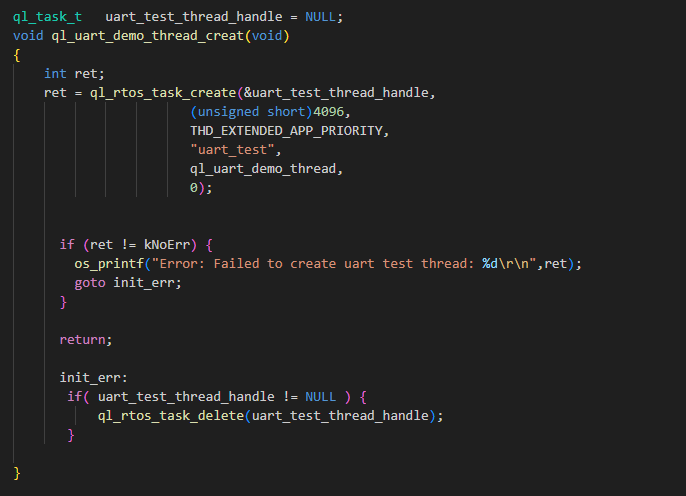
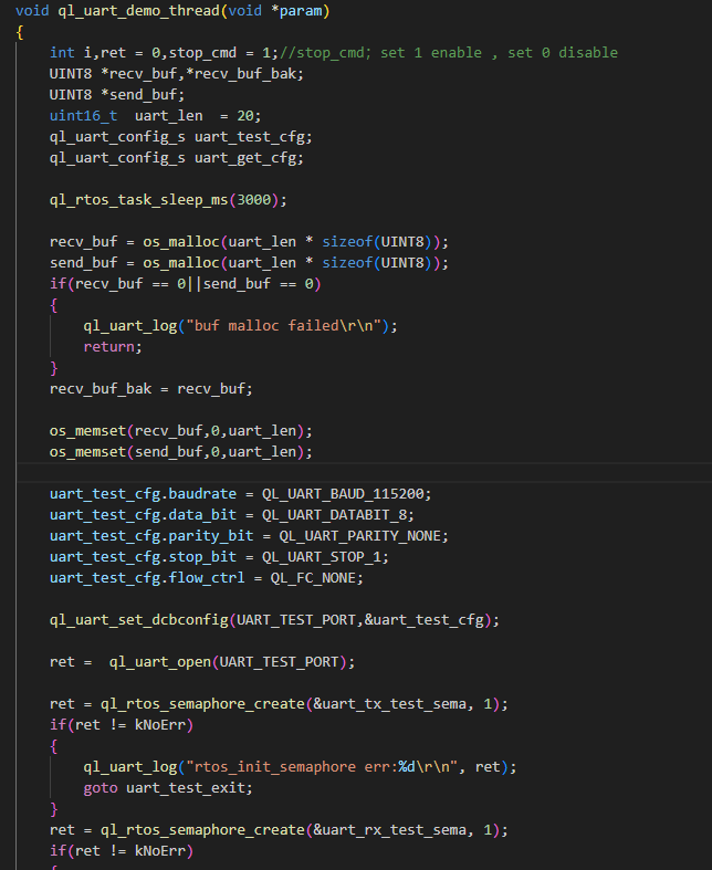
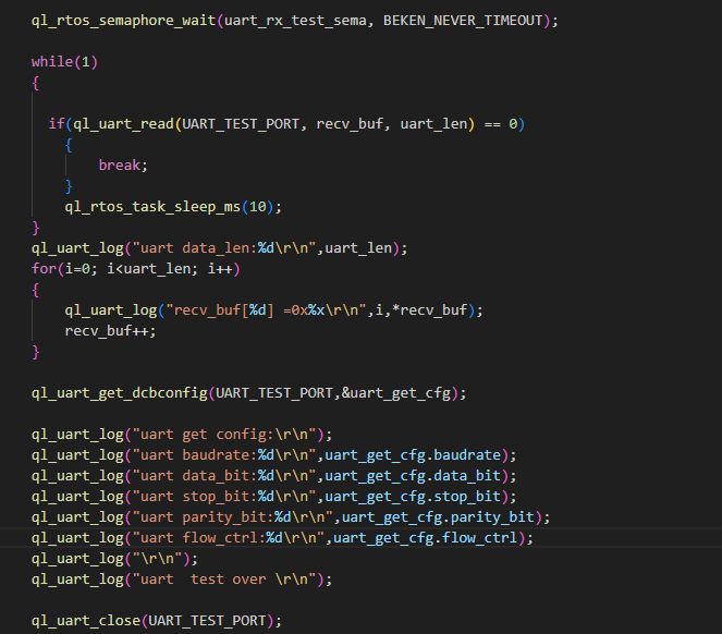
The example of how to use the UART API is provided in the ql_application/example/uart_demo/ql_uart_demo.c file in the module SDK. The descriptions of related functions are as follows.
ql_uart_demo_thread_creat(): This function creates a UART task. Call this function to run the demo.ql_uart_demo_thread(): This function executes the UART task. It initializes the UART port, sends, and receives data.
To run the demo, enable CFG_ENABLE_QUECTEL_UART macro definition. This will automatically trigger the execution of ql_uart_demo_thread_creat() to create a task.
Function Debugging
To debug the UART function, use the development board (e.g., FCM242D TE-B) with the module and follow these steps:
- Run the UART demo as explained in UART Operation.
- Recompile the firmware version and flash it to the module.
- Reboot the module.
- Open UART1 to start the test. Send the data of 20 bytes from UART1 to UART2, which will receive and echo the data, as shown below:
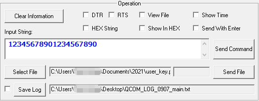
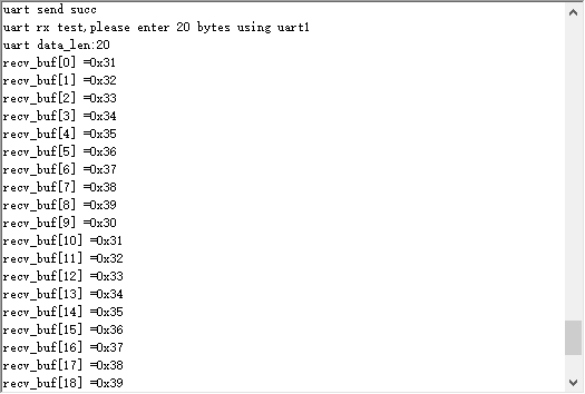
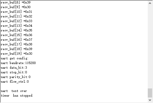
It can be confirmed that the UART function has been tested successfully by comparing the sent data in *Figure 7* with the received data in *Figure 8*.
SPI API
Header File
ql_spi.h, the header file of SPI API, is in the ql_components\api\ directory. Unless otherwise specified, all header files mentioned in this document are in this directory.
API Description
ql_spi_init
This function initializes SPI.
- Prototype
ql_spi_errcode_e ql_spi_init(ql_spi_id_e spi_id, ql_spi_config_s *spi_cfg);
- Parameters
spi_id: [In] SPI ID. See ql_spi_id_e for details.spi_cfg: [In] SPI configuration. See ql_spi_config_s for details.
- Return Value
Result code. See ql_spi_errcode_e for details.
ql_spi_id_e
The enumeration of SPI IDs:
typedef enum
{
    QL_SPI_ID0 = 0,
    QL_SPI_ID_MAX
} ql_spi_id_e;
- Member
| Member | Description |
|---|---|
| QL_SPI_ID0 | SPI0 |
| QL_SPI_ID_MAX | Maximum number of SPI IDs |
ql_spi_config_s
The structure of SPI configuration:
typedef struct
{
    uint32 clk;
    ql_spi_role_e role;
    ql_spi_bit_order_e bit_order;
} ql_spi_config_s;
- Parameter
| Type | Parameter | Description |
|---|---|---|
| uint32 | clk | SPI clock frequency. In master mode, the maximum value is 30 MHz. In slave mode, the maximum value is 20 MHz. |
ql_spi_role_e*` |
role | SPI master or slave selection. See ql_spi_role_e for details. |
ql_spi_pol_pha_mode_e |
pol_pha_mode | SPI clock phase and SPI clock polarity. See ql_spi_pol_pha_mode_e for details. |
ql_spi_bit_order_e*` |
bit_order* | SPI transmitting mode. See ql_spi_bit_order_e for details. |
ql_spi_role_e
The enumeration of SPI master or slave selection:
typedef enum {
    QL_SPI_ROLE_SLAVE = 0,
    QL_SPI_ROLE_MASTER
} ql_spi_role_e;
- Member
| Member | Description |
|---|---|
| QL_SPI_ROLE_SLAVE | SPI is configured as the slave. |
| QL_SPI_ROLE_MASTER | SPI is configured as the master. |
ql_spi_pol_pha_mode_e
The enumeration of SPI clock polarities and SPI clock phases:
typedef enum {
    QL_SPI_POL_PHA_MODE0 = 0,
    QL_SPI_POL_PHA_MODE1,
    QL_SPI_POL_PHA_MODE2,
    QL_SPI_POL_PHA_MODE3
} ql_spi_pol_pha_mode_e;
- Member
| Member | Description |
|---|---|
| QL_SPI_POL_PHA_MODE0 | SCK is at a low level during idle state. Sample data on the edge of the first period of SCK. |
| QL_SPI_POL_PHA_MODE1 | SCK is at a low level during idle state. Sample data on the edge of the second period of SCK. |
| QL_SPI_POL_PHA_MODE2 | SCK is at a high level during idle state. Sample data on the edge of the first period of SCK. |
| QL_SPI_POL_PHA_MODE3 | SCK is at a high level during idle state. Sample data on the edge of the second period of SCK. |
ql_spi_bit_order_e
The enumeration of SPI transmitting modes:
typedef enum {
    QL_SPI_MSB_FIRST = 0,
    QL_SPI_LSB_FIRST
} ql_spi_bit_order_e;
- Member
| Member | Description |
|---|---|
| QL_SPI_MSB_FIRST | MSB is sent first |
| QL_SPI_LSB_FIRST | LSB is sent first |
ql_spi_errcode_e
The enumeration of SPI API result codes:
typedef enum
{
    QL_SPI_SUCCESS = 0,
    QL_SPI_EXECUTE_ERR,
    QL_SPI_INVALID_PARAM_ERR,
    QL_SPI_NOT_INIT_ERR
} ql_spi_errcode_e;
- Member
| Member | Description |
|---|---|
| QL_SPI_SUCCESS | Successful execution |
| QL_SPI_EXECUTE_ERR | Failed execution |
| QL_SPI_INVALID_PARAM_ERR | Invalid parameter |
| QL_SPI_NOT_INIT_ERR | SPI is not initialized |
ql_spi_deinit
This function deinitializes the specified SPI.
- Prototype
ql_spi_errcode_e ql_spi_deinit(ql_spi_id_e spi_id);
- Parameters
spi_id: [In] SPI ID. See ql_spi_id_e for details.
- Return Value
Result code. See ql_spi_errcode_e for details.
ql_spi_write_bytes
This function sends the SPI data.
- Prototype
ql_spi_errcode_e ql_spi_write_bytes(ql_spi_id_e spi_id, void *data, uint32 size);
- Parameters
spi_id: [In] SPI ID. See ql_spi_id_e for details.data: [In] Sent SPI data.size: [In] Length of sent SPI data. Unit: byte.
- Return Value
Result code. See ql_spi_errcode_e for details.
ql_spi_read_bytes
This function reads the SPI data.
- Prototype
ql_spi_errcode_e ql_spi_read_bytes(ql_spi_id_e spi_id, void *data, uint32 size);
- Parameters
spi_id: [In] SPI ID. See ql_spi_id_e for details.data: [Out] Buffer for reading SPI data.size: [In] Length of read data. Unit: byte.
- Return Value
Result code. See ql_spi_errcode_e for details.
ql_spi_transfer
This function sends and receives SPI data.
- Prototype
ql_spi_errcode_e ql_spi_transfer(ql_spi_id_e spi_id, ql_spi_message_s *spi_msg);
- Parameters
spi_id: [In] SPI ID. See ql_spi_id_e for details.spi_msg: [In] Sent or received SPI data. See ql_spi_message_s for details.
- Return Value
Result code. See ql_spi_errcode_e for details.
ql_spi_message_s
The structure of the sent or received SPI data:
typedef struct {
    const void *send_buf;
    uint32 send_len;
    void *recv_buf;
    uint32 recv_len;
} ql_spi_message_s;
- Parameter
| Type | Parameter | Description |
|---|---|---|
| const void | send_buf | Sent data. |
| uint32 | send_len | Length of sent data. Unit: byte. |
| void | recv_buf | Received data. |
| uint32 | recv_len | Length of received data. Unit: byte. |
SPI Development Process
This chapter explains how to use the above SPI API in applications, and perform basic debugging, and test data transmission from both the master and the slave.
SPI Operation
The example of how to use the SPI API is provided in the ql_application/examplespi_demoql_spi_demo.c file in the module SDK. The descriptions of related functions are as follows:
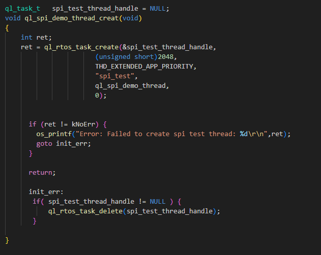
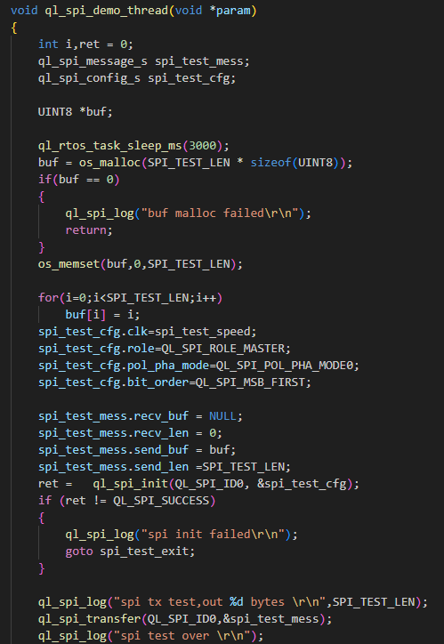
ql_spi_demo_thread_creat(): This function creates an SPI task. Call this function to run the SPI demo.ql_spi_demo_thread(): This function executes the SPI task. It initializes SPI and sends SPI data.
To run this example, enable CFG_ENABLE_QUECTEL_SPI macro definition. This will automatically trigger the execution of ql_spi_demo_thread_creat() to create a test task.
Function Debugging
To debug the SPI function, use the development board (e.g., FCM242D TE-B) with the module and follow these steps:
- Run the SPI demo as explained in SPI Operation.
- Recompile the firmware version and flash it to the module.
- Reboot the module.
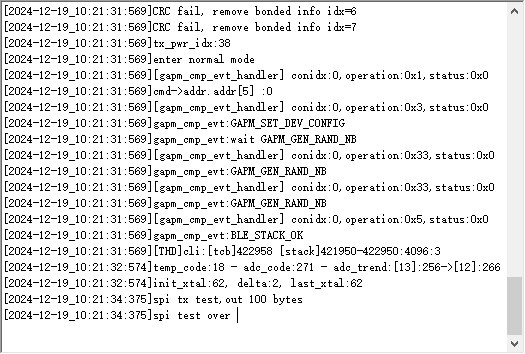
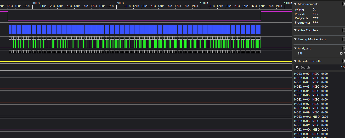
- Capture SPI waveforms through the logic analyzer.
- Open UART2 to obtain the debugging logs. The log information will be displayed as follows.
ADC API
Header File
ql_adc.h, the header file of ADC API, is in the ql_components\api\ directory. Unless otherwise specified, all header files mentioned in this document are in this directory.
API Description
ql_adc_init
This function initializes ADC.
- Prototype
ql_adc_errcode_e ql_adc_init(void);
Parameters
NoneReturn Value
Result code. See ql_adc_errcode_e for details.
ql_adc_errcode_e
The enumeration of ADC API result codes:
typedef enum
{
    QL_ADC_SUCCESS = 0,
    QL_ADC_EXECUTE_ERR,
    QL_ADC_INVALID_PARAM_ERR
} ql_adc_errcode_e;
- Member
| Member | Description |
|---|---|
| QL_ADC_SUCCESS | Successful execution |
| QL_ADC_EXECUTE_ERR | Failed execution |
| QL_ADC_INVALID_PARAM_ERR | Invalid parameter |
ql_adc_deinit
This function deinitializes ADC and releases the used resource.
ql_adc_errcode_e ql_adc_deinit(void);
Parameters
NoneReturn Value
Result code. See ql_adc_errcode_e for details.
ql_adc_start
This function starts ADC channel detection.
ql_adc_errcode_e ql_adc_start(ql_adc_channel_e chan);
- Parameters
chan: [In] ADC channel number. See ql_adc_channel_e for details.
- Return Value
Result code. See ql_adc_errcode_e for details.
ql_adc_channel_e
The enumeration of ADC channel numbers.
typedef enum
{
    QL_ADC_CHANNEL_1 = 1,
    QL_ADC_CHANNEL_2,
    QL_ADC_CHANNEL_3,
    QL_ADC_CHANNEL_4,
    QL_ADC_CHANNEL_5,
    QL_ADC_CHANNEL_6
} ql_adc_channel_e;
- Member
| Member | Description |
|---|---|
| QL_ADC_CHANNEL_1 | ADC1 |
| QL_ADC_CHANNEL_2 | ADC2 |
| QL_ADC_CHANNEL_3 | ADC3 |
| QL_ADC_CHANNEL_4 | ADC4 |
| QL_ADC_CHANNEL_5 | ADC5 |
| QL_ADC_CHANNEL_6 | ADC6 |
Since ADC5 and ADC6 channels occupy the UART interface pins in hardware, it is not recommended to use these two channels. See documents Hardware Design for details.
ql_adc_stop
This function stops ADC channel detection.
- Prototype
ql_adc_errcode_e ql_adc_stop(ql_adc_channel_e chan);
Parameters
chan: [In] ADC channel number. See ql_adc_channel_e for details.
Return Value
Result code. See ql_adc_errcode_e for details.
ql_adc_read
This function reads the sample data from the specified ADC channel.
- Prototype
ql_adc_errcode_e ql_adc_read(ql_adc_channel_e chan, uint16 *data, uint32 timeout);
- Parameters
chan: [In] ADC channel number. See ql_adc_channel_e for details.data: [Out] Read sample data.timeout: [In] Timeout for data reading.
- Return Value
Result code. See ql_adc_errcode_e for details.
ADC Development Process
This chapter explains how to use the above ADC API in applications, and perform basic debugging. In the following subsections, ADC channels 3 and 4 are used as examples.
ADC Operation
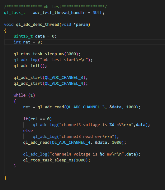
The example of how to use the ADC API is provided in the ql_application/example/adc_demo/ql_adc_demo.c file in the module SDK directory. The descriptions of related functions are as follows:
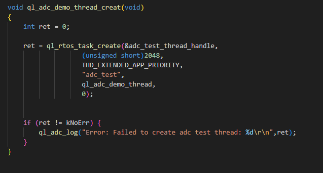
ql_adc_demo_thread_creat(): This function creates an ADC task. Call the function to run the ADC demo.ql_adc_demo_thread(): This function executes the ADC task. It initializes ADC and detects voltage.
To run the demo, enable CFG_ENABLE_QUECTEL_ADC macro definition. This will automatically trigger the execution of ql_adc_demo_thread_creat() and ql_adc_demo_thread()to create a test task, as shown below.
Function Debugging
To debug the ADC function, use the development board (e.g., FCM242D TE-B) with the module and follow these steps:
- Run the ADC demo as explained in ADC Operation.
- Recompile the firmware version and flash it to the module.
- Reboot the module.
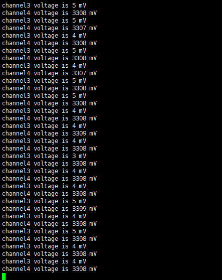
- Open UART port 2 to capture the debugging logs. Change the input voltage of the pin and the detection value changes accordingly. The log information will be displayed as follows:
PWM API
Header File
ql_pwm.h, the header file of PWM API, is in the ql_components\api\ directory. Unless otherwise specified, all header files mentioned in this document are in this directory.
API Description
ql_pwm_init
This function initializes PWM.
- Prototype
ql_pwm_errcode_e ql_pwm_init(ql_pwm_channel_e chan, uint32 period, uint32 duty);
- Parameters
chan: [In] PWM channel. See ql_pwm_channel_e for details.period: [In] PWM period. Actual output frequency: F = 26 MHz /period.duty: [In] PWM duty cycle. It is less than theperiodvalue.
- Return Value
Result code. See ql_pwm_errcode_e for details.
ql_pwm_channel_e
The enumeration of PWM channels.
typedef enum {
    QL_PWM_0 = 0,
    QL_PWM_1,
    QL_PWM_2,
    QL_PWM_3,
    QL_PWM_4,
    QL_PWM_5
} ql_pwm_channel_e;
- Member
| Member | Description |
|---|---|
| QL_PWM_0 | PWM 0 |
| QL_PWM_1 | PWM 1 |
| QL_PWM_2 | PWM 2 |
| QL_PWM_3 | PWM 3 |
| QL_PWM_4 | PWM 4 |
| QL_PWM_5 | PWM 5 |
ql_pwm_errcode_e
The enumeration of PWM API result codes:
typedef enum {
    QL_PWM_SUCCESS = 0,
    QL_PWM_EXECUTE_ERR,
    QL_PWM_INVALID_PARAM_ERR
} ql_pwm_errcode_e;
- Member
| Member | Description |
|---|---|
| QL_PWM_SUCCESS | Successful execution |
| QL_PWM_EXECUTE_ERR | Failed execution |
| QL_PWM_INVALID_PARAM_ERR | Invalid parameter |
ql_pwm_deinit
This function deinitializes PWM.
ql_pwm_errcode_e ql_pwm_deinit(ql_pwm_channel_e pwm_channel);
- Parameters
pwm_channel: [In] PWM channel. See ql_pwm_channel_e for details.
- Return Value
Result code. See ql_pwm_errcode_e for details.
ql_pwm_enable
This function enables PWM output.
- Prototype
ql_pwm_errcode_e ql_pwm_enable(ql_pwm_channel_e pwm_channel);
- Parameters
pwm_channel: [In] PWM channel. See ql_pwm_channel_e for details.
- Return Value
Result code. See ql_pwm_errcode_e for details.
ql_pwm_disable
This function disables PWM output.
- Prototype
ql_pwm_errcode_e ql_pwm_disable(ql_pwm_channel_e pwm_channel);
- Parameters
pwm_channel: [In] PWM channel. See ql_pwm_channel_e for details.
- Return Value
Result code. See ql_pwm_errcode_e for details.
ql_pwm_update_param
This function updates the parameters of PWM configuration. The configuration takes effect in the next PWM period.
- Prototype
ql_pwm_errcode_e ql_pwm_update_param(ql_pwm_channel_e pwm_channel, uint32 period, uint32 duty_cycle);
- Parameters
pwm_channel: [In] PWM channel. See ql_pwm_channel_e for details.period: [In] PWM period. Actual output frequency: F = 26 MHz /period.duty_cycle: [In] PWM duty cycle. It is less than theperiodvalue.
- Return Value
Result code. See ql_pwm_errcode_e for details.
PWM Development Process
This chapter explains how to use the above PWM API in applications and perform basic debugging. In the following subsections, GPIO6 pin corresponding to PWM0 is used as an example.
PWM Operation
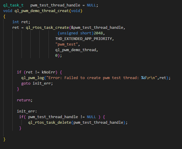
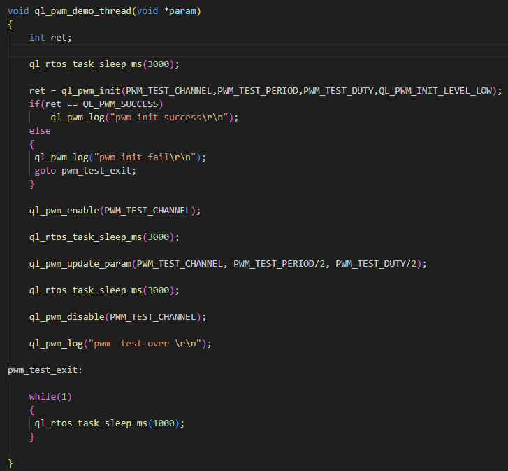
The example of how to use the PWM API is provided in the ql_application/example/pwm_demo/ql_pwm_demo.c file in the module SDK. The descriptions of related functions are as follows:
ql_pwm_demo_thread_creat(): This function creates a PWM task. Call the function to run PWM demo.
To run the demo, enable CFG_ENABLE_QUECTEL_PWM macro definition. This will automatically trigger the execution of ql_pwm_demo_thread_creat() to create a test task.
Function Debugging
To debug the PWM function, use the development board (e.g., FCM242D TE-B) with the module and follow these steps:
- Run the PWM demo as explained in PWM Operation.
- Recompile the firmware version and flash it to the module.
- Reboot the module.
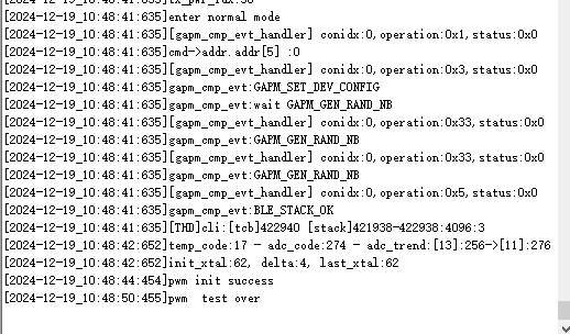
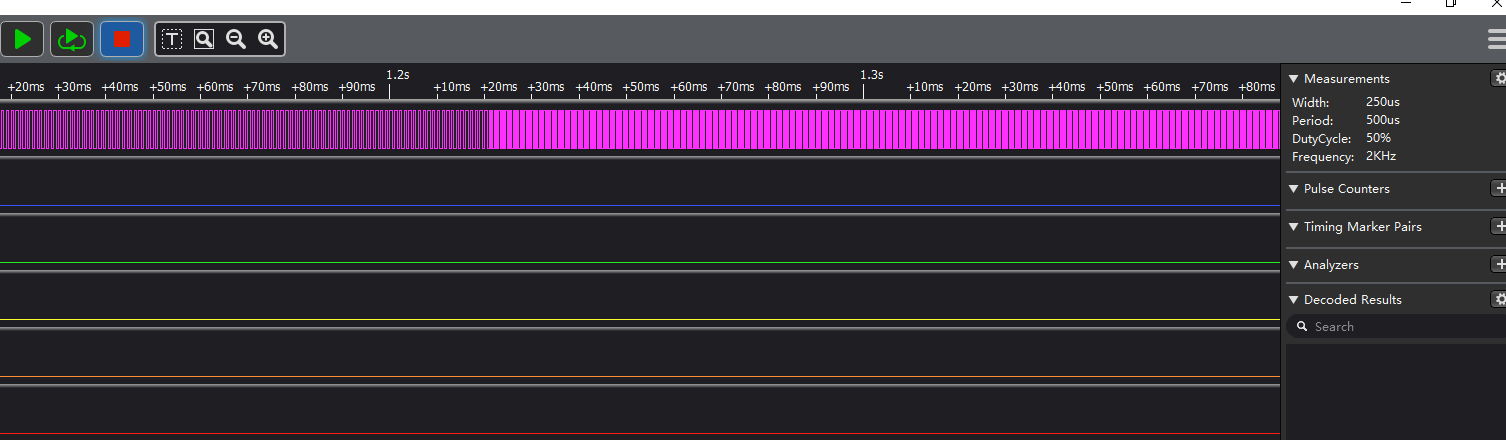
- Capture the pin waveforms of PWM0 through the logic analyzer.
- Open UART2 to obtain the debugging logs. The log information will be displayed as follows:
I2C API
Header File
ql_i2c.h, the header file of I2C API, is in the ql_components\api\ directory. Unless otherwise specified, all header files mentioned in this document are in this directory.
API Description
ql_i2c_init
This function initializes the I2C bus.
- Prototype
ql_i2c_errcode_e ql_i2c_init(ql_i2c_id_e iic_id, ql_i2c_speed_mode_e speed_mode, ql_i2c_addr_mode_e addr_mode, uint16 slave_addr);
- Parameters
iic_id: [In] I2C bus ID. See ql_i2c_id_e for details. Currently, only I2C2 is supported.speed_mode: [In] I2C clock frequency. See ql_i2c_speed_mode_e for details.addr_mode: [In] Length of slave device address. See ql_i2c_addr_mode_e for details.slave_addr: [In] Address used for communication when the module acts as either a master device or a slave device.
- Return Value
Result code. See ql_i2c_errcode_e for details.
ql_i2c_id_e
The enumeration of I2C bus ID:
typedef enum {
    QL_I2C2 = 0
} ql_i2c_id_e;
- Member
| Member | Description |
|---|---|
| QL_I2C2 | I2C2 |
ql_i2c_speed_mode_e
The enumeration of I2C clock frequencies:
typedef enum {
    QL_I2C_SPEED_STANDARD = 0,
    QL_I2C_SPEED_FAST
} ql_i2c_speed_mode_e;
- Member
| Member | Description |
|---|---|
| QL_I2C_SPEED_STANDARD | Standard mode (Clock frequency is 100 kHz) |
| QL_I2C_SPEED_FAST | Fast mode (Clock frequency is 400 kHz) |
ql_i2c_addr_mode_e
The enumeration of slave device address lengths:
typedef enum {
    QL_I2C_ADDR_SIZE_7BIT = 0,
    QL_I2C_ADDR_SIZE_10BIT
} ql_i2c_addr_mode_e;
- Member
| Member | Description |
|---|---|
| QL_I2C_ADDR_SIZE_7BIT | Slave device address length is 7 bits. |
| QL_I2C_ADDR_SIZE_10BIT | Slave device address length is 10 bits (Not supported currently). |
ql_i2c_errcode_e
The enumeration of I2C API result codes:
typedef enum {
    QL_I2C_SUCCESS = 0,
    QL_I2C_INIT_ERR,
    QL_I2C_ID_INIT_ERR,
    QL_I2C_SM_BUS_ERR,
    QL_I2C_ACK_TIMEOUT_ERR,
    QL_I2C_WRITE_ERR,
    QL_I2C_READ_ERR
} ql_i2c_errcode_e;
- Member
| Member | Description |
|---|---|
| QL_I2C_SUCCESS | Successful execution |
| QL_I2C_INIT_ERR | Failed I2C initialization |
| QL_I2C_ID_INIT_ERR | I2C bus ID error |
| QL_I2C_SM_BUS_ERR | I2C bus error |
| QL_I2C_ACK_TIMEOUT_ERR | Timeout for getting ACK |
| QL_I2C_WRITE_ERR | Failed to write data to I2C bus |
| QL_I2C_READ_ERR | Failed to read data from I2C bus |
ql_i2c_deinit
This function releases I2C resource.
- Prototype
ql_i2c_errcode_e ql_i2c_deinit(ql_i2c_id_e iic_id);
- Parameters
iic_id: [In] I2C bus ID. See ql_i2c_id_e for details. Currently, only I2C2 is supported.
- Return Value
Result code. See ql_i2c_errcode_e for details.
ql_i2c_master_write
This function sends data in I2C master mode.
- Prototype
ql_i2c_errcode_e ql_i2c_master_write(ql_i2c_id_e iic_id,uint32 dev_addr,const uint8* data,uint32 size);
- Parameters
iic_id: [In] I2C bus ID. See ql_i2c_id_e for details. Currently, only I2C2 is supported.dev_addr: [In] I2C slave device address.data: [Out] Buffer for sending data.size: [In] Length of sent data. Unit: byte.
- Return Value
Result code. See ql_i2c_errcode_e for details.
ql_i2c_master_read
This function receives data in I2C master mode.
- Prototype
ql_i2c_errcode_e ql_i2c_master_read(ql_i2c_id_e iic_id,uint32 dev_addr,uint8 *data,uint32 size);
- Parameters
iic_id: [In] I2C bus ID. See ql_i2c_id_e for details. Currently, only I2C2 is supported.dev_addr: [In] I2C slave device address.data: [In] Buffer for receiving data.size: [In] Length of received data. Unit: byte.
- Return Value
Result code. See ql_i2c_errcode_e for details.
ql_i2c_master_mem_write
This function sends data in I2C master mode and sends the memory address of the slave device.
- Prototype
ql_i2c_errcode_e ql_i2c_master_mem_write(ql_i2c_id_e iic_id,uint32 dev_addr,uint32 mem_addr,ql_i2c_mem_addr_size_e mem_size,uint8* data,uint32 size);
- Parameters
iic_id: [In] I2C bus ID. See ql_i2c_id_e for details. Currently, only I2C2 is supported.dev_addr: [In] I2C slave device address.mem_addr: [In] Memory address of slave device.mem_size: [In] Size of memory address of slave device. See ql_i2c_mem_addr_size_e for details.data: [Out] Buffer for sending data.size: [In] Length of sent data. Unit: byte.
- Return Value
Result code. See ql_i2c_errcode_e for details.
ql_i2c_mem_addr_size_e
The enumeration of memory address sizes:
typedef enum {
    QL_I2C_MEM_ADDR_SIZE_8BIT = 0,
    QL_I2C_MEM_ADDR_SIZE_16BIT
} ql_i2c_mem_addr_size_e;
- Member
| Member | Description |
|---|---|
| QL_I2C_MEM_ADDR_SIZE_8BIT | Memory address size is 8 bits |
| QL_I2C_MEM_ADDR_SIZE_16BIT | Memory address size is 16 bits |
ql_i2c_master_mem_read
This function receives data in I2C master mode and sends the memory address of the slave device.
- Prototype
ql_i2c_errcode_e ql_i2c_master_mem_read(ql_i2c_id_e iic_id,uint32 dev_addr,uint32 mem_addr,ql_i2c_mem_addr_size_e mem_size,uint8* data,uint32 size);
- Parameters
iic_id: [In] I2C bus ID. See ql_i2c_id_e for details. Currently, only I2C2 is supported.dev_addr: [In] I2C slave device address.mem_addr: [In] Memory address of slave device.mem_size: [In] Size of memory address of slave device. See ql_i2c_mem_addr_size_e for details.data: [In] Buffer for receiving data.size: [In] Length of received data. Unit: byte.
- Return Value
Result code. See ql_i2c_errcode_e for details.
I2C Development Process
This chapter explains how to use the above I2C API in applications and perform basic debugging. I2C requires the use of peripherals for communication. EEPROM chip (model: AT24C02) is applied in this example.
I2C Operation
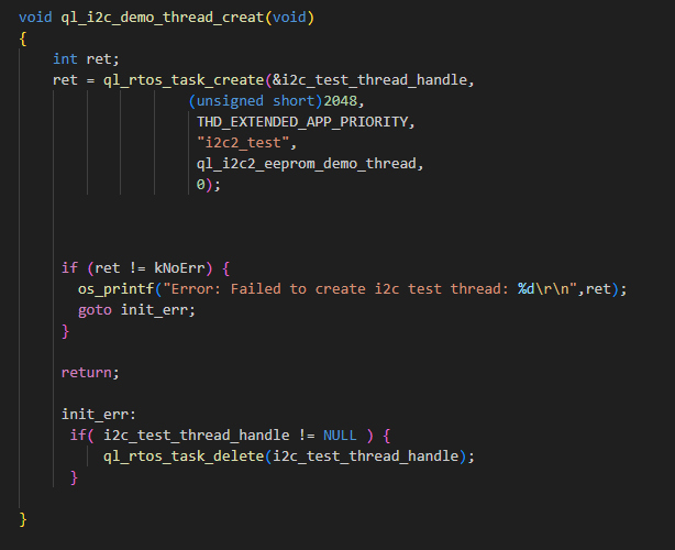
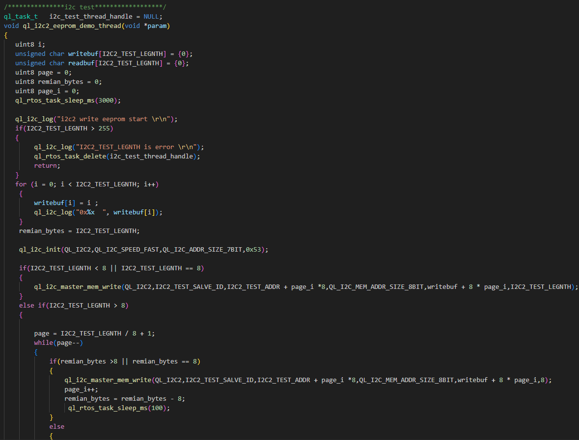
The example of how to use the I2C API is provided in the ql_application/example/i2c_eeprom_demo/ql_i2c_eeprom_demo.c file in the module SDK. The description of related function is as follows:
ql_i2c_demo_thread_creat(): This function creates an I2C task. Call this function to run the demo.
To run this demo, enable CFG_ENABLE_QUECTEL_I2C2 macro definition. This will automatically trigger the execution of ql_i2c_demo_thread_creat() to create a test task.
Function Debugging
To debug the I2C function, use the development board (e.g., FCM242D TE-B) with the module and follow these steps:
- Run the I2C demo as explained in I2C Operation.
- Recompile the firmware version and flash it to the module.
- Reboot the module.
- Open UART2 to obtain the debugging logs. The log information will be displayed as follows:
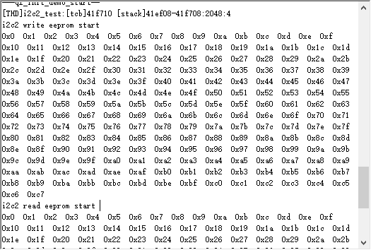
The data can be written and read successfully as shown in the figure above. Therefore, it can be said that the I2C function test has passed.
Appendix References
Terms and Abbreviations
| Abbreviation | Description |
|---|---|
| ACK | Acknowledgement |
| ADC | Analog-to-Digital Converter |
| API | Application Programming Interface |
| CLK | Clock |
| FC | Flow Control |
| CTS | Clear To Send |
| EEPROM | Electrically Erasable Programmable Read-Only Memory |
| GPIO | General-Purpose Input/Output |
| HW | Hardware |
| I2C | Inter-Integrated Circuit |
| ID | Identifier |
| IoT | Internet of Things |
| LSB | Least Significant Bit |
| MSB | Most Significant Bit |
| PWM | Pulse Width Modulation |
| RTOS | Real-Time Operating System |
| RTS | Request To Send |
| SCK | Serial Clock |
| SDK | Software Development Kit |
| SPI | Serial Peripheral Interface |
| UART | Universal Asynchronous Receiver/Transmitter |