
40PIN Testing

GPIO Testing
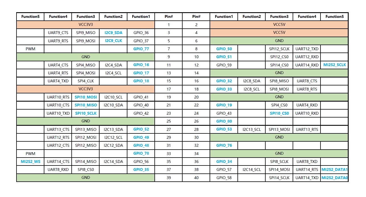
Select a GPIO pin from 40pin to test the GPIO functionality. For example, use pin3 from 40pin for testing, where pin3 corresponds to gpio_num 36. The mapping between pins and gpio_num can be found in pinmap.
Connection diagram (with red wire connecting to the positive probe of the multimeter, and the white wire connecting to the negative probe of the multimeter.):
Use SHELL Commands
The system has the lgpiod service enabled by default. Execute the following commands sequentially to test the GPIO functionality of pin3 from 40pin:
rgs c 999 go 4#Use the go command to open /dev/gpiochip4rgs c 999 gso 0 36#Use the gso command to set gpio 36 to output mode (the 0 here is the return value from the previous command; please adjust as needed)rgs c 999 gw 0 36 0#Set gpio 36 to low level (measured pin voltage: 0V)rgs c 999 gw 0 36 1#Set gpio 36 to high level (measured pin voltage: 3.3V)
Using C Code
Create a gpio.c file with the following content:
#include <stdlib.h>
#include <lgpio.h>

int main(int argc, char **argv)
{
    int gpio_num = atoi(argv[1]);
    int pin_level = atoi(argv[2]);
    int handle = lgGpiochipOpen(4);

    lgGpioClaimOutput(handle, 0, gpio_num, 0);
    lgGpioWrite(handle, gpio_num, pin_level);
}
Compile: gcc -o gpio gpio.c -llgpio
Execute: ./gpio 36 0 #Set gpio 36 to low level (measured pin voltage: 0V)
Execute: ./gpio 36 1 #Set gpio 36 to high level (measured pin voltage: 3.3V)
I2C Testing
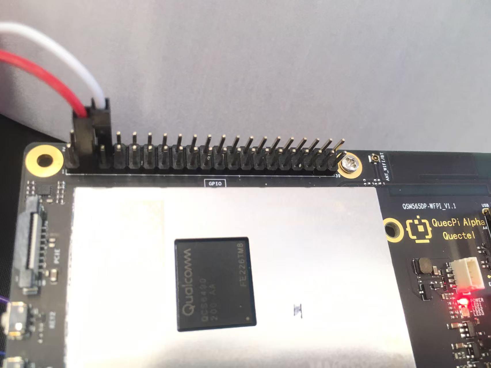
Pin3 and pin5 from 40PIN are configured as data and clock pins of I2C by default. To test the I2C interface, connect an external I2C device, such as the Waveshare Environmental Sensor Expansion Board, via 40pPIN pins .
Connection diagram:
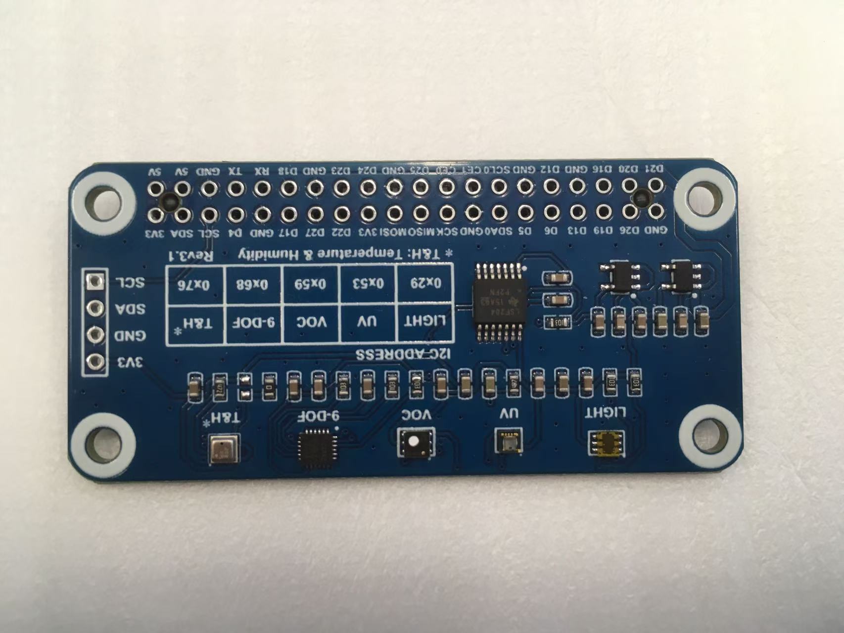
Waveshare Environmental Sensor Expansion Board

QuecPi 40PIN Pins
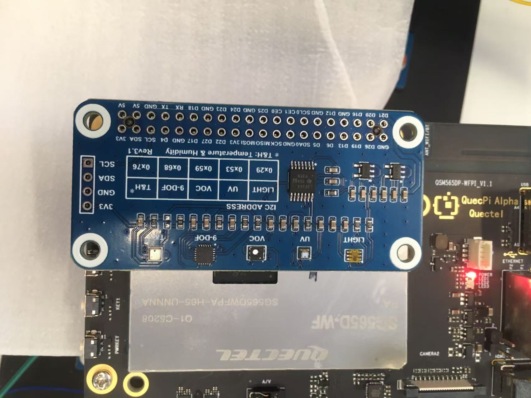
QuecPi Alpha with Environmental Sensor Expansion Board
Use C Code
Testing steps:
Create an envtest.c file with the following content:
#include <stdio.h>
#include <lgpio.h>

#define I2C_DEV_NUM 9
#define BME280_ADDR 0x76

int32_t digT[3],digP[9],digH[6];
int32_t t_fine = 0.0;

double compensate_P(int32_t adc_P)
{
    double pressure = 0.0;
    double v1,v2;
    v1 = (t_fine / 2.0) - 64000.0;
    v2 = (((v1 / 4.0) * (v1 / 4.0)) / 2048) * digP[5];
    v2 = v2 + ((v1 * digP[4]) * 2.0);
    v2 = (v2 / 4.0) + (digP[3] * 65536.0);
    v1 = (((digP[2] * (((v1 / 4.0) * (v1 / 4.0)) / 8192)) / 8)  + ((digP[1] * v1) / 2.0)) / 262144;
    v1 = ((32768 + v1) * digP[0]) / 32768;
    if(v1 == 0)
        return 0;
    pressure = ((1048576 - adc_P) - (v2 / 4096)) * 3125;
    if (pressure < 0x80000000)
        pressure = (pressure * 2.0) / v1;
    else
        pressure = (pressure / v1) * 2;
    v1 = (digP[8] * (((pressure / 8.0) * (pressure / 8.0)) / 8192.0)) / 4096;
    v2 = ((pressure / 4.0) * digP[7]) / 8192.0;
    pressure = pressure + ((v1 + v2 + digP[6]) / 16.0) ;
    return (pressure/100);
}

double compensate_T(int32_t adc_T)
{
    double temperature = 0.0;
    double v1,v2;
    v1 = (adc_T / 16384.0 - digT[0] / 1024.0) * digT[1];
    v2 = (adc_T / 131072.0 - digT[0] / 8192.0) * (adc_T / 131072.0 - digT[0] / 8192.0) * digT[2];
    t_fine = v1 + v2;
    temperature = t_fine / 5120.0;
    return temperature;
}

double compensate_H(int32_t adc_H)
{
    double var_h = t_fine - 76800.0;
    if (var_h == 0)
        return 0;
    var_h = (adc_H - (digH[3] * 64.0 + digH[4]/16384.0 * var_h)) *
        (digH[1] / 65536.0 * (1.0 + digH[5] / 67108864.0 * var_h * (1.0 + digH[2] / 67108864.0 * var_h)));
    var_h = var_h * (1.0 - digH[0] * var_h / 524288.0);
    if (var_h > 100.0)
        var_h = 100.0;
    else if (var_h < 0.0)
        var_h = 0.0;
    return var_h;
}

void get_calib_param(int handle)
{
    uint8_t calib[32];
    for(int i=0;i<24;i++) {
        calib[i] = lgI2cReadByteData(handle, 0x88 + i);
    }
    calib[24] = lgI2cReadByteData(handle, 0xA1);
    for(int i=25,o=0;i<32;i++,o++) {
        calib[i] = lgI2cReadByteData(handle, 0xE1 + o);
    }
    digT[0] = (calib[1] << 8) | calib[0];
    digT[1] = (calib[3] << 8) | calib[2];
    digT[2] = (calib[5] << 8) | calib[4];
    digP[0] = (calib[7] << 8) | calib[6];
    digP[1] = (calib[9] << 8) | calib[8];
    digP[2] = (calib[11] << 8) | calib[10];
    digP[3] = (calib[13] << 8) | calib[12];
    digP[4] = (calib[15] << 8) | calib[14];
    digP[5] = (calib[17] << 8) | calib[16];
    digP[6] = (calib[19] << 8) | calib[18];
    digP[7] = (calib[21] << 8) | calib[20];
    digP[8] = (calib[23] << 8) | calib[22];
    digH[0] = calib[24];
    digH[1] = (calib[26] << 8) | calib[25];
    digH[2] = calib[27];
    digH[3] = (calib[28] << 4) | (0x0f & calib[29]);
    digH[4] = (calib[30] << 4) | ((calib[29] >> 4) & 0x0f);
    digH[5] = calib[31];
    for(int i=1;i<2;i++)
        if((digT[i] & 0x8000) != 0) digT[i] = (-digT[i] ^ 0xFFFF) + 1;
    for(int i=1;i<8;i++)
        if ((digP[i] & 0x8000) != 0)    digP[i]=(-digP[i] ^ 0xFFFF) + 1 ;
    for(int i=0;i<6;i++)
        if ((digH[i] & 0x8000) != 0) digH[i] = (-digH[i] ^ 0xFFFF) + 1;
}

int main(int argc, char **argv)
{
    uint8_t data[8];
    double value[3];
    int handle = lgI2cOpen(I2C_DEV_NUM, BME280_ADDR, 0);

    lgI2cWriteByteData(handle, 0xF2, 0x01);
    lgI2cWriteByteData(handle, 0xF4, 0x27);
    lgI2cWriteByteData(handle, 0xF5, 0xA0);
    get_calib_param(handle);

    for(int i=0;i<8;i++) {
        data[i] = lgI2cReadByteData(handle, 0xF7 + i);
    }
    value[0] = (data[0] << 12) | (data[1] << 4) | (data[2] >> 4);
    value[1] = (data[3] << 12) | (data[4] << 4) | (data[5] >> 4);
    value[2] = (data[6] << 8)  |  data[7];
    value[0] = compensate_P(value[0]);
    value[1] = compensate_T(value[1]);
    value[2] = compensate_H(value[2]);

    printf("pressure:    %7.2f hPa\n", value[0]);
    printf("temperature: %7.2f C\n"  , value[1]);
    printf("humidity:    %7.2f %\n"  , value[2]);
    lgI2cClose(handle);
}
Compile: gcc -o envtest envtest.c -llgpio
Run: ./envtest #Output data include collected air pressure, temperature, and humidity information
SPI Testing
Test SPI function of 40pin with Waveshare 2.23 inc OLED displayer
Connection diagram:
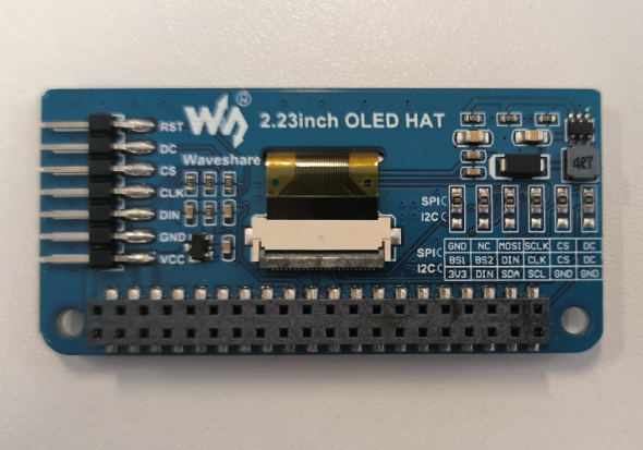
Waveshare OLED displayer
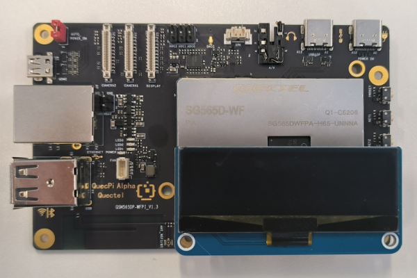
QuecPi Alpha with Waveshare OLED displayer
Test steps:
wget http://www.waveshare.net/w/upload/c/c5/2.23inch-OLED-HAT-Code.7z #Download source code from Waveshare
7z x 2.23inch-OLED-HAT-Code.7z #Extract the source code
cd 2.23inch-OLED-HAT-Code/Without\ scrolling/Raspberry\ Pi/SPI/c #Navigate to the source directory
Modify the source code according to the content of the following patch:
diff -r -u "2.23inch-OLED-HAT-Code/Without scrolling/Raspberry Pi/c/examples/main.c" quecpi/c/examples/main.c
--- "2.23inch-OLED-HAT-Code/Without scrolling/Raspberry Pi/c/examples/main.c"	2023-12-20 03:19:38.000000000 +0000
+++ quecpi/c/examples/main.c	2025-08-15 07:34:39.959415415 +0000
@@ -17,10 +17,13 @@
     char value[10]={'0', '1', '2', '3', '4', '5', '6', '7', '8', '9'};
     time_t now;
     struct tm *timenow;
-
-    if(DEV_ModuleInit() != 0) {
-		return -1;
-	}
+    extern int GPIO_Handle;
+    extern int SPI_Handle;
+    GPIO_Handle = lgGpiochipOpen(4); if (GPIO_Handle < 0) { printf( "gpiochip4 Export Failed\n"); return -1; }
+    lgGpioClaimOutput(GPIO_Handle, 0, 119     , LG_LOW); //enable OLED_DC mode
+    lgGpioClaimOutput(GPIO_Handle, 0, OLED_RST, LG_LOW);
+    lgGpioClaimOutput(GPIO_Handle, 0, OLED_DC , LG_LOW);
+    SPI_Handle = lgSpiOpen(10, 0, 10000000, 0);
     SSD1305_begin();
     SSD1305_bitmap(7, 0, waveshare_ch,112,32);
     SSD1305_display();
Only in quecpi/c/lib/Config: .DEV_Config.h.un~
diff -r -u "2.23inch-OLED-HAT-Code/Without scrolling/Raspberry Pi/c/lib/Config/DEV_Config.h" quecpi/c/lib/Config/DEV_Config.h
--- "2.23inch-OLED-HAT-Code/Without scrolling/Raspberry Pi/c/lib/Config/DEV_Config.h"	2023-12-20 03:23:11.000000000 +0000
+++ quecpi/c/lib/Config/DEV_Config.h	2025-08-15 07:32:05.844626084 +0000
@@ -41,8 +41,8 @@

 //OLED Define
 #define OLED_CS         8
-#define OLED_RST        25
-#define OLED_DC         24
+#define OLED_RST        19
+#define OLED_DC         33
Compile: make
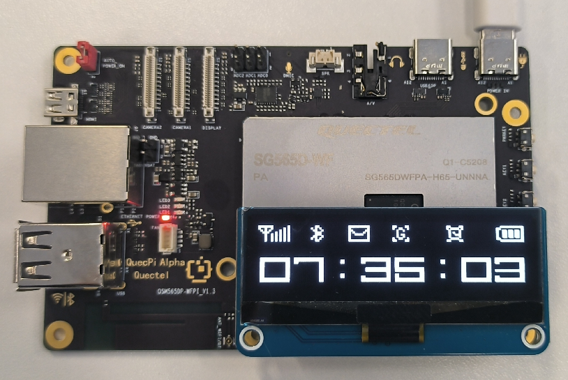
Run: ./main
Expected output:
UART Testing
Configure pin8 and pin10 from 40PIN to UART functionality by default. Connect the RX of a USB-to-serial module to pin8 and the TX to pin10.
Connection diagram: 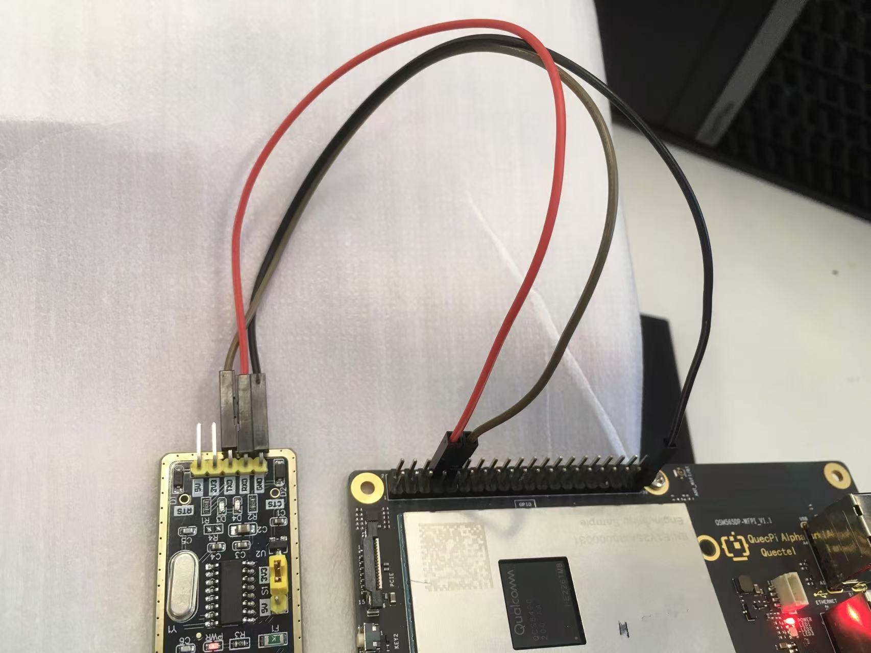
Use C Code
Create a uart.c file with the following content:
#include <stdio.h>
#include <string.h>
#include <lgpio.h>

int strip_head_and_tail(char *data, int data_len)
{
    int found_tail = 0;
    if (data_len > 0 && data[0] == '\r') {
        bcopy(data + 1, data, data_len-1);
        data_len--;
    }
    if (data_len > 0 && data[0] == '\n') {
        bcopy(data + 1, data, data_len-1);
        data_len--;
    }
    if (data_len > 0 && data[data_len - 1] == '\r') {
        data_len--;
        data[data_len] = 0;
        found_tail = 1;
    }
    if (data_len > 0 && data[data_len - 1] == '\n') {
        data_len--;
        data[data_len] = 0;
        found_tail = 1;
    }
    return found_tail;
}

int main(int argc, char **argv)
{
    int handle = lgSerialOpen("/dev/ttyHS2", 115200, 0);
    char data[512];
    int data_len = 0;
    for (;;) {
        int read_len = lgSerialRead(handle,
            data + data_len, sizeof(data) - data_len);
        if (read_len > 0) {
            data_len += read_len;
        }
        if (strip_head_and_tail(data, data_len)) {
            printf("received: %s\n", data);
            lgSerialWrite(handle, "Received.\r\n", 11);
        }
        lguSleep(100);
    }
    lgSerialClose(handle);
}
Compile: gcc -o uart uart.c -llgpio
Run: ./uart #Connect a USB-to-serial module to the PC and use serial communication software (e.g., PuTTY) to interact with the service program. Input the message via PuTTY and end with enter button, and the program will echo received messages and reply with "Received.".
Use Python Script
Create a server script uart.py with the following content:
import serial
import threading

PORT = '/dev/ttyHS2'
BAUDRATE = 115200
TIMEOUT = 1

ser = serial.Serial(PORT, BAUDRATE, timeout=TIMEOUT)

def read_and_echo(ser):
    while True:
        data = ser.readline()
        if data:
            print(f"Received: {data.decode().strip()}")
            ser.write(“Received.\r\n”)

def main():
    if ser.is_open:
        print(f"Serial port {PORT} is open. Echo service started.")
        thread = threading.Thread(target=read_and_echo, args=(ser,))
        thread.daemon = True
        thread.start()

        try:
            while True:
                pass
        except KeyboardInterrupt:
            print("Exiting program.")
    else:
        print(f"Failed to open serial port {PORT}.")

    ser.close()
    print(f"Serial port {PORT} is closed.")

if __name__ == "__main__":
    main()
Run: python test.py #Connect a USB-to-serial module to the PC and use serial communication software (e.g., PuTTY) to interact with the service program. Input the message via PuTTY and end with enter button, and the program will echo received messages and reply with "Received.".
PWM Testing
Configure pin33 from 40PIN to PWM by default. Select the Waveshare 4pin PWM fan for testing.
Using C Code
Create a pwm.c file with the following content:
#include <stdio.h>
#include <lgpio.h>
int main(int argc, char **argv)
{
      int h;
      int gpio = 78;
      float pwmFrequency = 1000;
      float pwmDutyCycle = 50;

      h = lgGpiochipOpen(4);
      if (h < 0) {
          printf("ERROR: %s (%d)\n", lguErrorText(h), h);
          return 1;
      }

      int e = lgGpioClaimOutput(h, 0, gpio, 0);
      if (e < 0) {
          printf("ERROR: %s (%d)\n", lguErrorText(e), e);
          return 1;
      }

      e = lgTxPwm(h, gpio, pwmFrequency, pwmDutyCycle, 0, 0);
      if (e < 0) {
          printf("ERROR: %s (%d)\n", lguErrorText(e), e);
          return 1;
      }

      lguSleep(5);
      lgGpioFree(h, gpio);
      lgGpiochipClose(h);
      return 0;
}
Compile: gcc pwm.c -o pwm -llgpio
Run: ./pwm #The fan will operate at medium speed. Adjust pwmDutyCycle in the code to change the fan speed.