
AI-Vision-Car User Guide
Purchase Link
Pre-Assembly Instructions
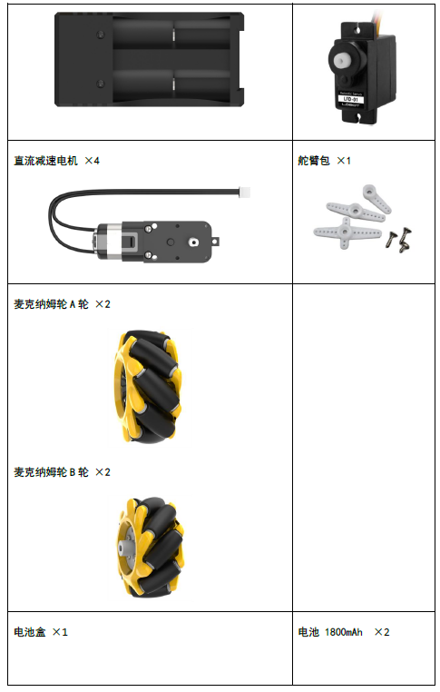
Shipping List
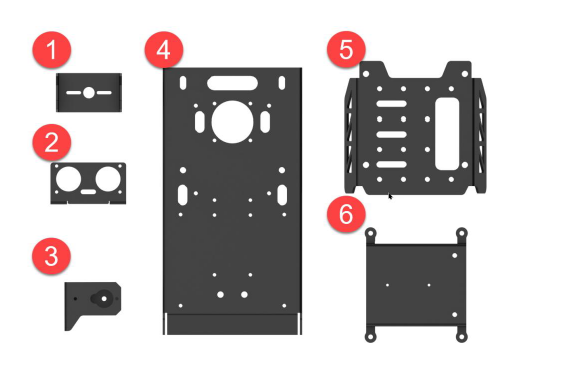
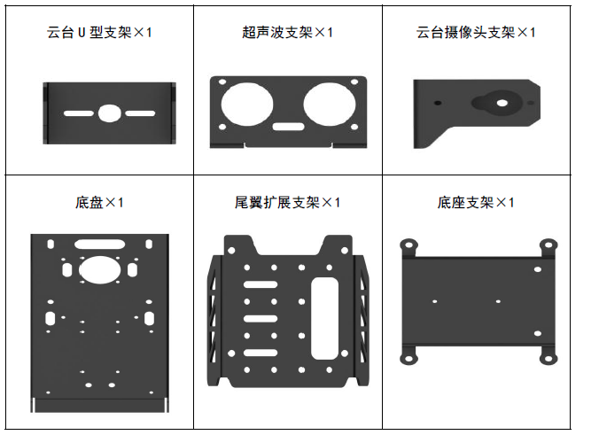
Profile Accessories
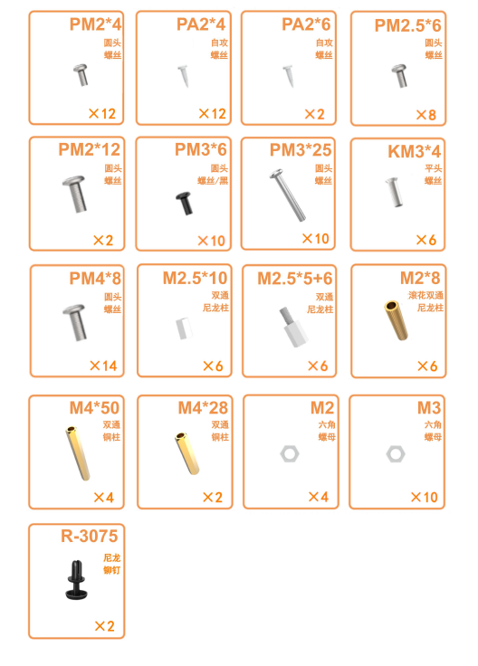
Screw Accessories
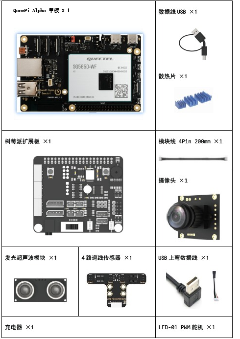
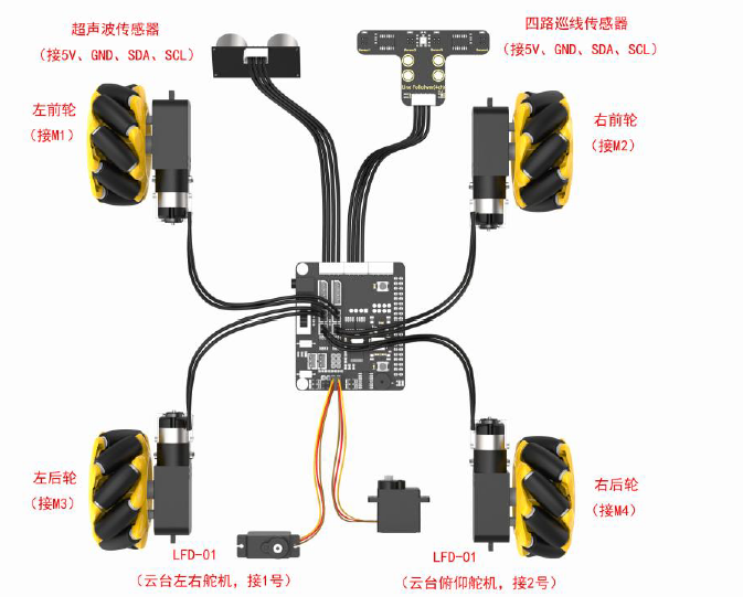
Electronic Accessories
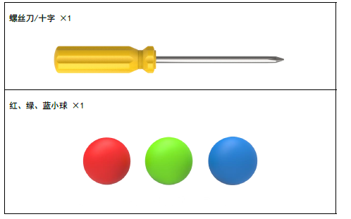
Tools
Assembly Steps
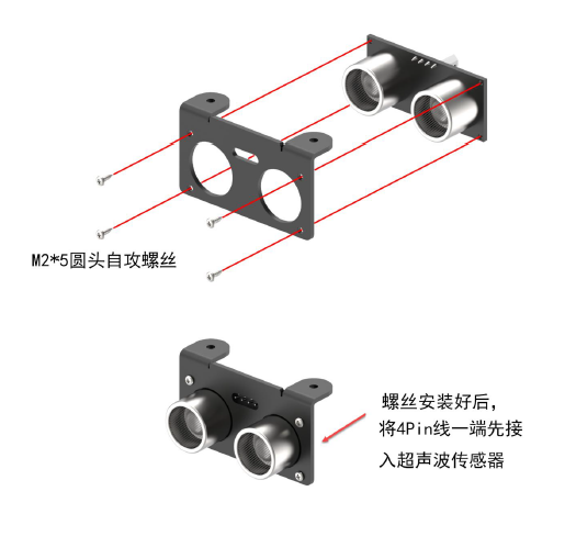
Use 4 M2*5 round head self-tapping screws to install the LED ultrasonic sensor to the ultrasonic bracket.
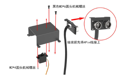
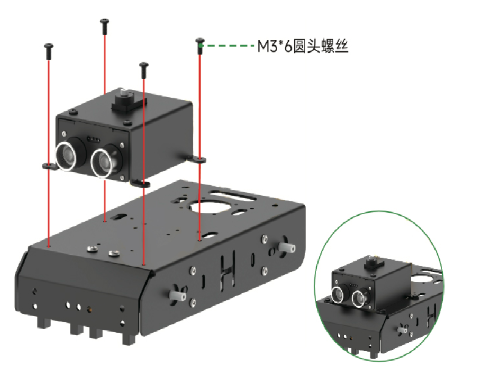
Use 2 M2*4 round head machine screws to install the PWM servo on the base bracket; use 2 black M3*6 round head machine screws to install the assembled ultrasonic bracket on the base bracket (connect the 4pin wire before assembly).
Use 8 M3*25 machine screws and 8 M3 nuts to fix the four TT motors to the chassis.
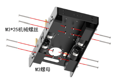
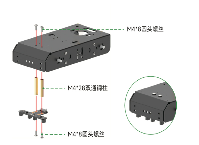
Use 2 M4*8 round head machine screws and 2 M4*28 double-pass copper pillars to fix them on the chassis. Then use 2 M4*8 round head machine screws to fix the four-line tracking sensor on the chassis. After installing the four-line tracking sensor, insert one end of the 4pin wire into the sensor interface.
Use 4 black M3*6 round head machine screws to install the assembled base bracket on the chassis.
Use 3 M2.5*5 single-pass nylon pillars and 3 M2.5*10 double-pass nylon pillars to fix the main board. Align the female headers of the expansion board with the male headers of the main board (one-to-one alignment) and insert them into the main board. Then use 2 M2.5*6 round head machine screws to fix the expansion board and main board together.
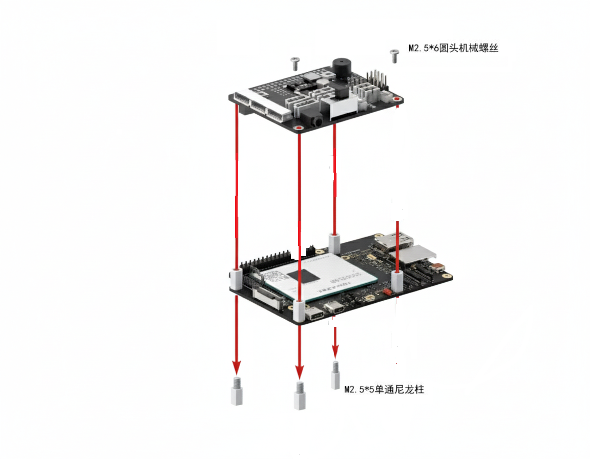
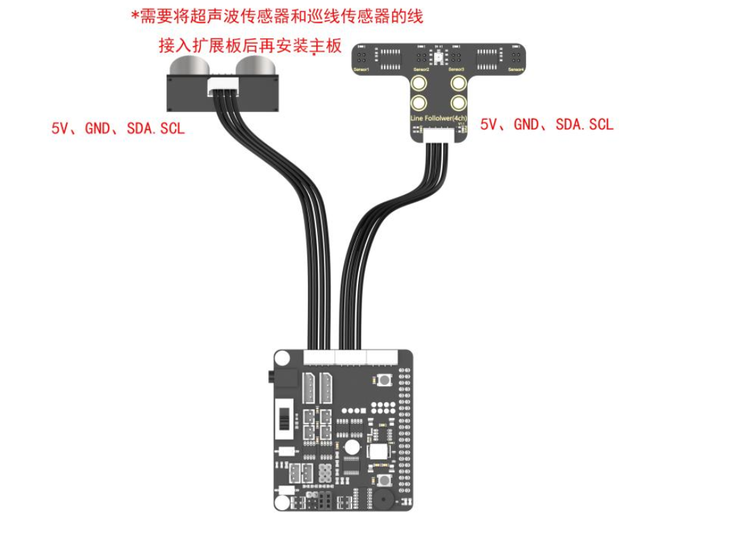
Use 4 M2.5*6 round head machine screws to fix the assembled main board on the chassis, and connect the four-line tracking sensor and LED ultrasonic sensor to the corresponding interfaces on the expansion board.
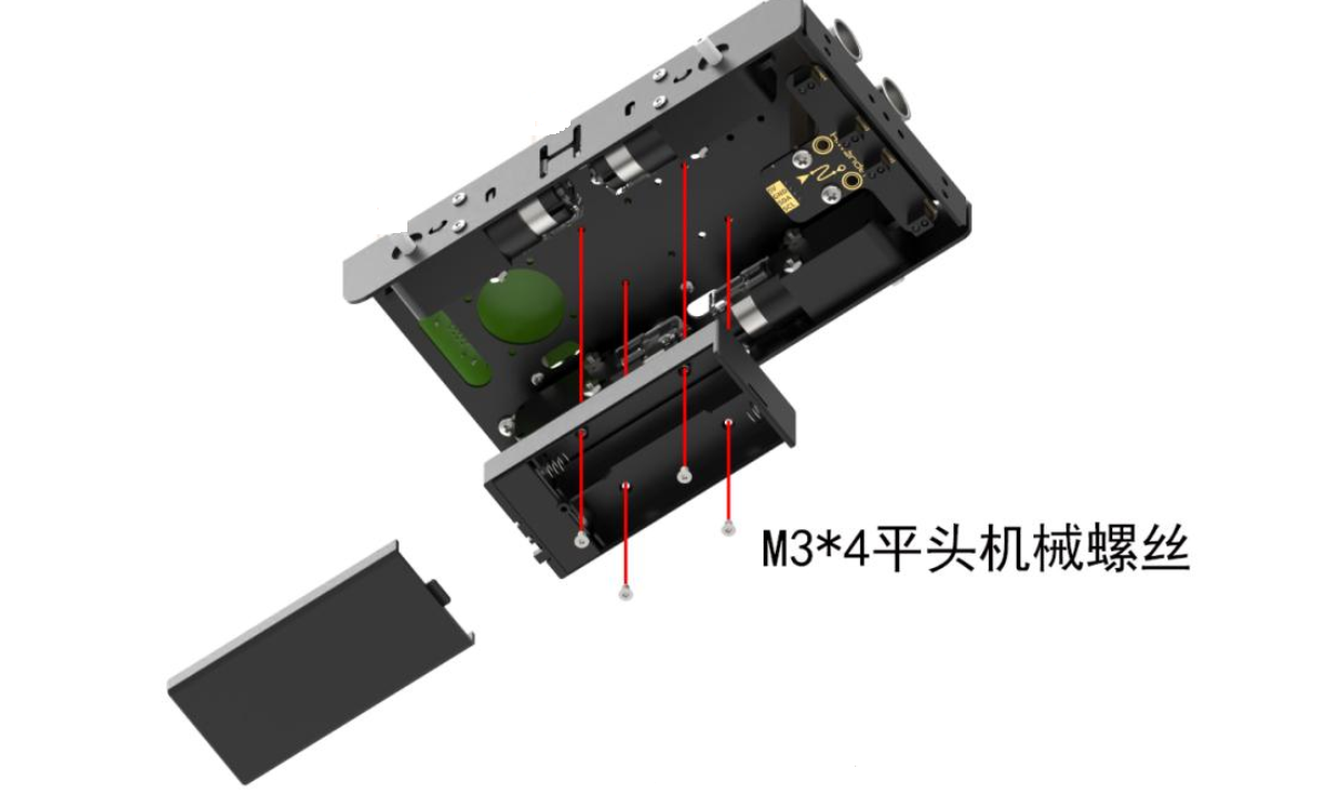
Use 4 M3*4 flat head machine screws to fix the battery box under the chassis.
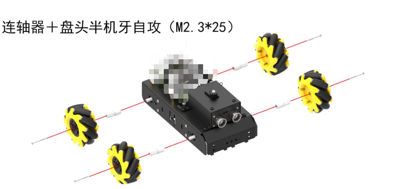
Install the coupling on the wheel shaft of the TT motor, and use 4 pan head half-thread self-tapping M2.3*25 screws to fix the Mecanum wheel with the wheel shaft of the TT motor.
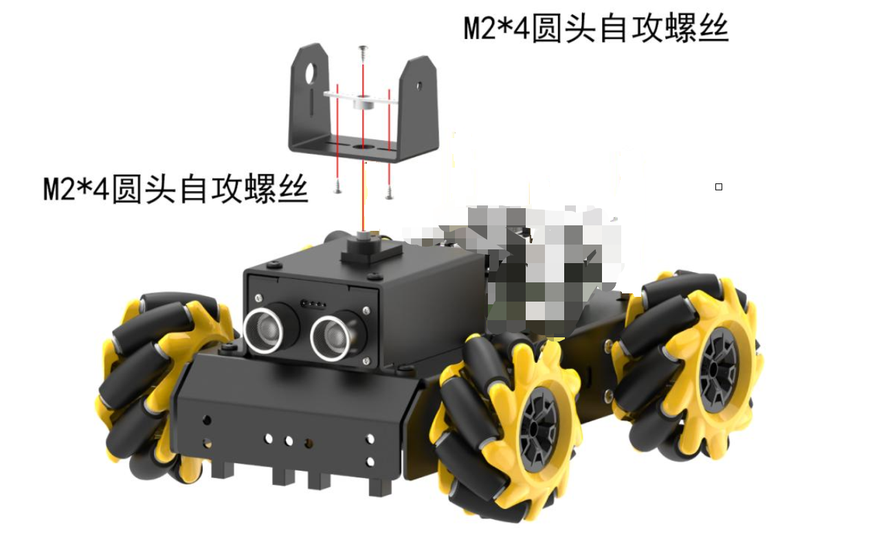
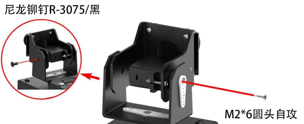
Use 2 M2*4 round head self-tapping screws to fix the plastic shaft on the gimbal U-shaped bracket, then use 1 M2*4 round head self-tapping screw to install the assembled gimbal U-shaped bracket on the car.
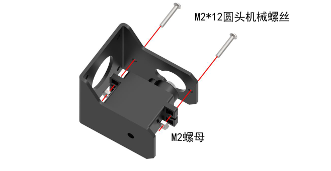
Use 2 M2*12 round head machine screws and 2 M2 nuts to fix the PWM servo on the gimbal camera bracket.
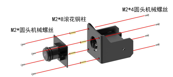
Use 4 M2*4 round head machine screws and 4 M2*8 knurled copper pillars to fix them on the gimbal camera bracket. Then use 2 M2*4 round head machine screws to fix the camera on the gimbal camera bracket.
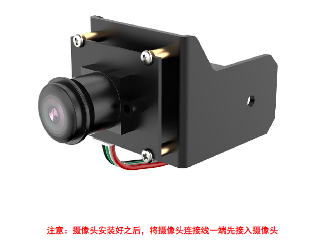
Use 1 M2*6 round head self-tapping screw to fix the assembled gimbal camera bracket on the car.
Connect the 4 TT motor interfaces and 2 gimbal servo interfaces (orange to S (signal wire), red to +, brown to -) with the expansion board.
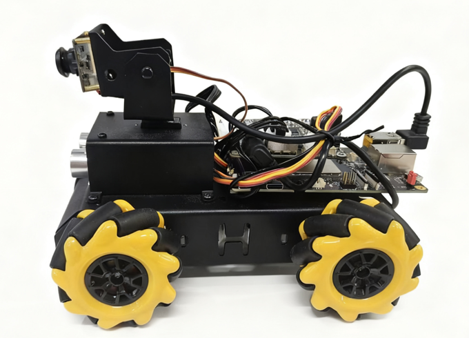
After installation, the car body is as follows.
Pre-Use Environment Deployment
Download Environment
Before use, you need to download the relevant environment. The download link is as follows:
Deployment Environment
After downloading the deployment environment, push the deployment environment to the device via adb push, then decompress it.
# Push to device
adb push ./quecpi_smartcar.zip /mnt
adb shell

# Decompress the package:
unzip /mnt/quecpi_smartcar.zip -d /mnt/

# Add executable permissions to all files in the run/ directory and deploy_container.sh:
chmod +x /mnt/quecpi_smartcar/service_config/run/*
chmod +x /mnt/quecpi_smartcar/deploy_container.sh
After decompression, you get the following directory structure:
quecpi_smartcar/
├── docker_images/
│   └── docker_quecpi_smart_car.tar    # Docker image file
├── ros2_ws/
│   ├── src/                           # ROS2 source code
│   └── software/                      # Software tools
├── service_config/
│   ├── rules.d/                       # udev rule files
│   ├── service/                       # systemd service files
│   └── run/                           # Boot fast start scripts
└── deploy_container.sh                # Complete deployment script
Ensure Communication
To ensure that the QuecPi main board and expansion board can communicate, you need to enable i2c9 and uart12 on the 40pin. The enabling method is as follows:
On the QuecPi main board, first modify the quecpi_config.ini configuration file, use vi /etc/quecpi_config/quecpi_config.ini to modify it to the following content:
i2c9=enable
spi10=disable
uart12_2w=enable
i2c13=disable
spi14=disable
heartbeat_color=green
led_red_brightness=0
led_blue_brightness=0
led_green_brightness=0
heartbeat_switch=on
Enter quecpi_config 40pin set, then restart the QuecPi main board to take effect.
Complete Deployment Process (deploy_container.sh)
After the above restart, you need to plug in the network cable or connect to wifi to ensure you are in a networked environment, then execute the deployment script.
# Run complete deployment
/mnt/quecpi_smartcar/deploy_container.sh
After the deployment script is executed successfully, if the deployment is successful, the following prompt will appear:
[SUCCESS] Deployment completed successfully!
ROS2 application has been automatically started!
Pre-Use Device Preparation
Battery Charging
Since the battery cannot be fully charged during transportation, it is recommended to fully charge the battery before the first startup. The specific charging method is as follows:
- Take out the battery charger, install two 18650 batteries (optional) into the battery charger according to the positive and negative poles (positive to positive, negative to negative). Note! Do not reverse the positive and negative poles of the battery! Then connect the battery charger (optional) and charging head (5V 3A, need to be prepared by yourself) through a data cable, and finally connect the power supply.
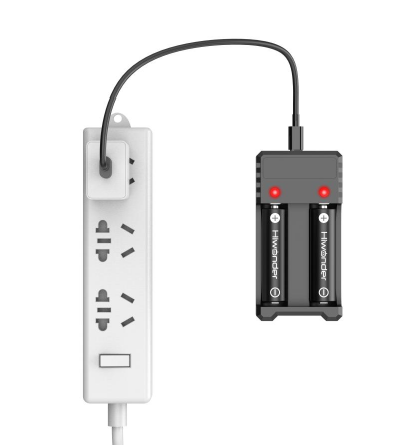
- Wait for charging to complete (the adapter indicator light is green when not powered, red when powered on represents charging (charging time is about 5 hours), the indicator light changes from red to green represents charging completion). After charging is complete, please unplug the charger as soon as possible, do not keep charging.
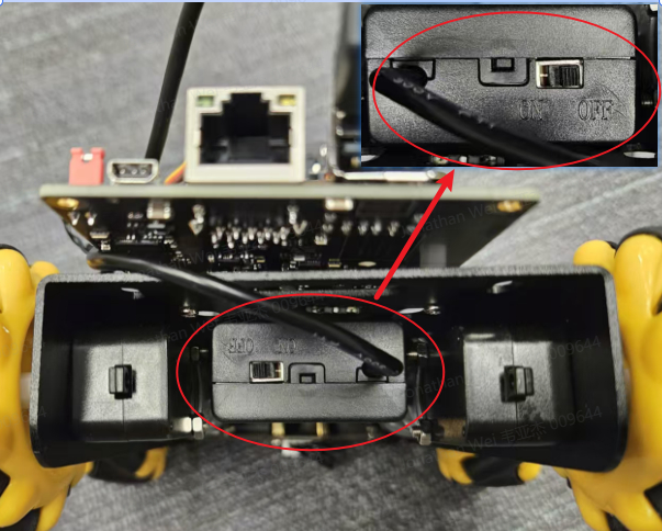
- After charging is complete, please ensure that the battery box switch is set to "OFF" before installing the battery. (OFF position see startup section)
Mobile APP Installation
Android system: Scan the QR code below for installation.

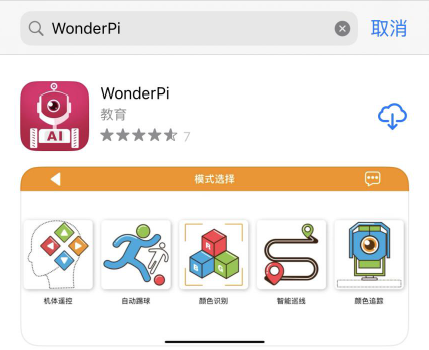
iOS system: You can go to the App Store to search for "WonderPi" and download and install it.
Startup Preparation
- Install two charged 18650 batteries in the battery box at the bottom of the car according to the positive and negative poles, then turn the bottom switch to "ON".
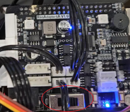
- Then push the expansion board switch from "OFF" to "ON". At this time, LED1 and LED2 of the expansion board are always on. After a moment, LED1 changes from always on to flashing once every 1 second, the gimbal returns to the initial posture, and the buzzer makes a "beep" sound, indicating that the device has successfully started. (It takes about 30s to hear the "beep" sound)
Note:
- LED2 is the power indicator light, which lights up when powered on and is always on during device operation. If the light dims, it means the power is out and needs to be charged;
- LED1 is the communication indicator light. The device's default network connection mode is direct connection mode. After the device starts successfully, LED1 flashes once every 1S; if it is set to LAN mode, LED1 will be always on;
- During device operation, if LED1 and LED2 lights dim and remain always on, it means the power is out and needs to be charged.
Device Trial
Pre-Use Connection
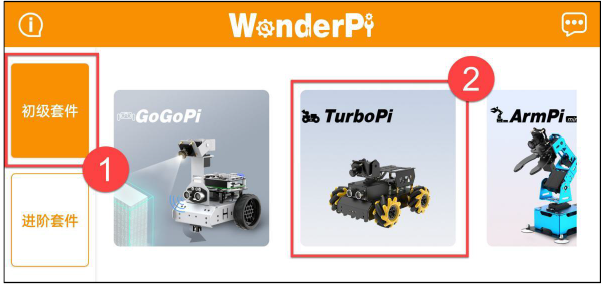
- After the device starts successfully, it will enter AP direct connection mode and generate a hotspot starting with "HW". Open the mobile APP "WonderPi" on your phone, and click "Beginner Kit" and "TurboPi" in sequence.
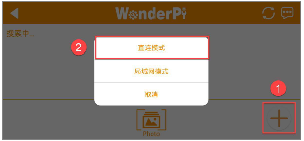
- Click the "+" button in the lower right corner of the interface and select "Direct Connection Mode".
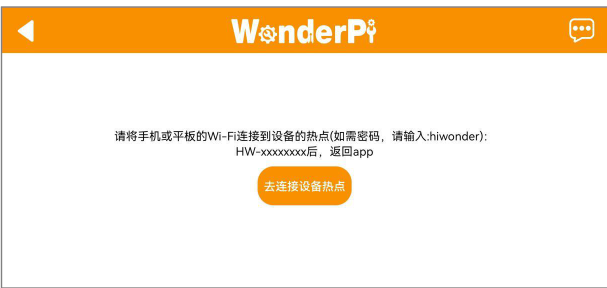
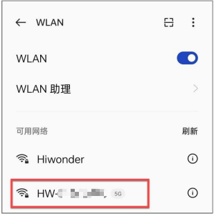
- Click the "Go to connect device hotspot" button to go to the settings interface and connect to the hotspot starting with "HW". When connecting, you need to enter the password "hiwonder".
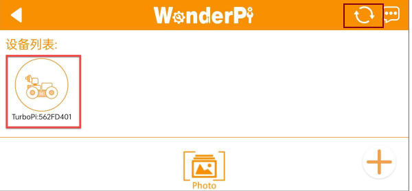
- After successful connection, return to the mobile APP. After a moment, when the icon shown in the figure below is found, the connection is successful. (If it is not displayed below the device list, you can click the refresh button in the upper right corner to refresh the device)
Note: If a popup prompt "Network unavailable, continue to connect?" appears, click the "Keep Connection" button.
- Click the TurboPi icon in the figure above to enter the game mode selection interface, as shown below
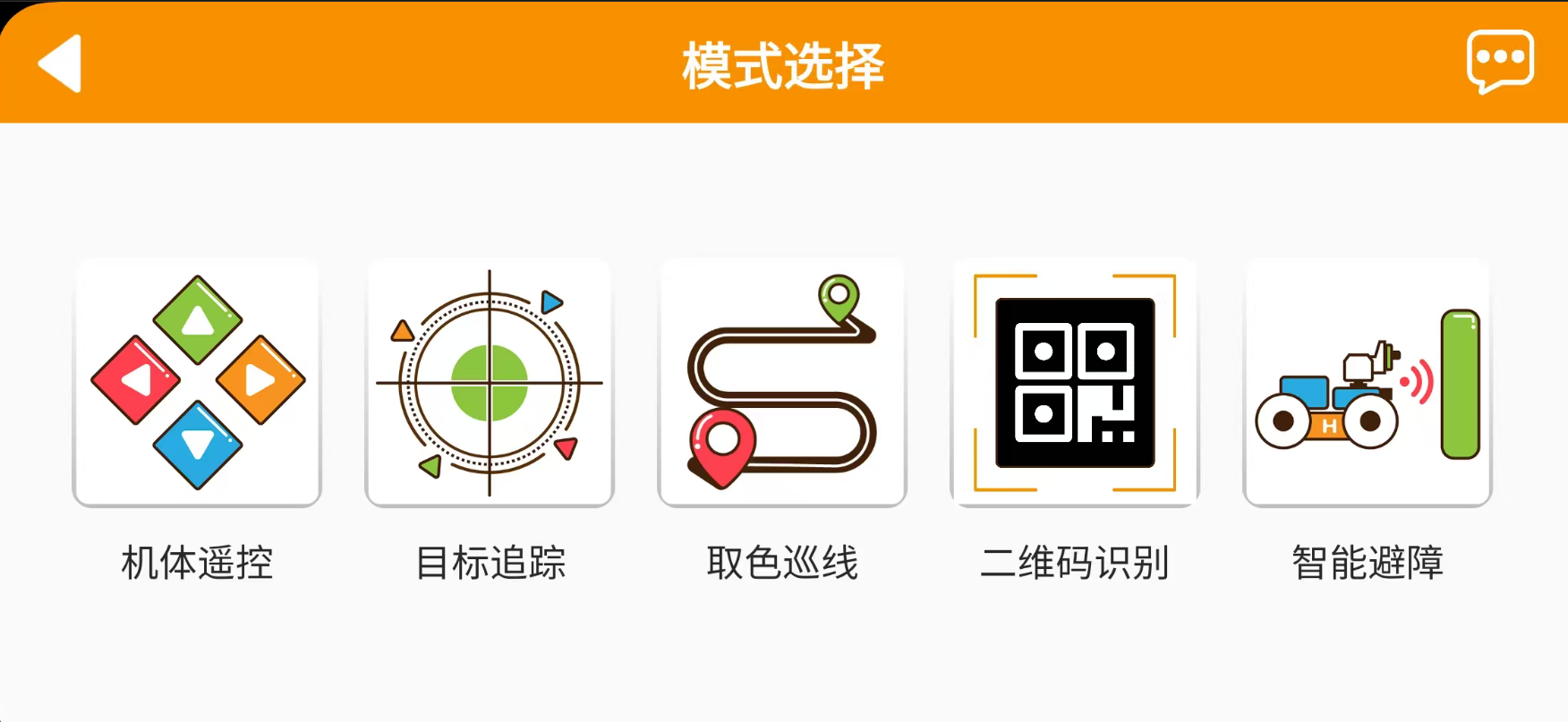
Body Remote Control
Introduction: This gameplay can control the car movement and ultrasonic RGB lights in real time; the interface is divided into four parts, the descriptions and function icons of each part are as follows:
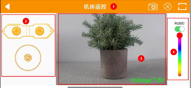
① Status bar: Can control the exit of gameplay, screenshot of return video, and hide the status bar;
② Control bar: Can control car movement; (mainly introduces control bar functions)
③ Return video: Shows the return video of the camera and displays the device voltage value;
④ Ultrasonic RGB light adjustment: Can control the ultrasonic module's RGB light to turn on, turn off, and light up different colors.
The operation steps are described as follows:
| Interface Distribution | Icon | Corresponding Function |
|---|---|---|
 |
Drag the middle button to control the TurboPi car body to move in all directions. | |
 |
Click or long press this icon to control the TurboPi car body to rotate counterclockwise in place. | |
 |
Click or long press this icon to control the TurboPi car body to rotate clockwise in place. |
To return to the gameplay selection interface, click the return arrow in the upper left corner.
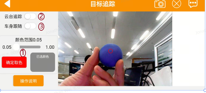
Target Tracking
Introduction: Click "Target Tracking" to enter the gameplay interface. After this gameplay is enabled, it can realize the function of the car moving with the movement of the target color.
The operation steps are as follows:
- In the above screen, clicking the button at ① will change from "Color Picking" to "Confirm Color Picking". In the video captured by the camera on the right, move the red dot to select the target color, then click "Confirm Color Picking" to confirm the color;
- Click the "Gimbal Tracking" button at ② to start the tracking gameplay. At this time, the device's camera will follow the selected color target movement, and the car body will not move;
- To realize the car body following gameplay, you need to select both the "Gimbal Tracking" at ② and the "Car Body Following" at ③ buttons. At this time, the device's car body and gimbal will follow the selected color target movement.
Note:
- Please perform in a well-lit indoor environment, but try to avoid direct strong light.
- During recognition, please avoid objects with the same or similar color as the target color in the camera view to avoid interference with recognition.
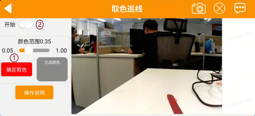
Color Line Following
Introduction: Click "Color Line Following" to enter the gameplay interface. After starting this gameplay, the car can move forward along black or red lines.
The operation steps are as follows:
- In the above screen, clicking the button at ① will change from "Color Picking" to "Confirm Color Picking". In the video captured by the camera on the right, move the red dot to select the target color, then click "Confirm Color Picking" to confirm the color;
- Click the "Start" button at ② to move forward along the line of the target color.
Note:
- Please perform in a well-lit indoor environment, but try to avoid direct strong light.
- During recognition, please avoid objects with the same or similar color as the target color in the camera view to avoid interference with recognition.
QR Code Recognition
Introduction: Click "QR Code" recognition to enter the gameplay interface. After this gameplay is started, the car's camera can recognize different QR codes and execute corresponding actions.
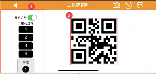
① The left side of the interface is the QR code switch and selection area;
② The right side of the interface is the QR code screen.
The operation steps are as follows:
Click the "Start Recognition" button and select different QR codes. Place the QR code in front of the device's camera for recognition. The device will execute different actions after recognizing different QR codes.
| Button Icon | Function Description |
|---|---|
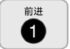
 |
QR code for the car to execute forward action |
 |
QR code for the car to execute backward action |
 |
QR code for the car to execute left movement action |
 |
QR code for the car to execute right movement action |
 |
Display selected QR code information |
Note:
- The distance for recognizing QR codes should not be too close or too far. Generally, the distance between the QR code image and the camera is 35cm for best results.
- Please perform in a well-lit indoor environment, but try to avoid direct strong light.
Smart Obstacle Avoidance
Click "Smart Obstacle Avoidance" to enter the gameplay interface. After this gameplay is started, the car can identify whether there are obstacles ahead through ultrasonic waves and avoid them.
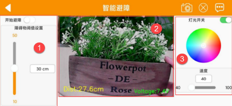
① The left side of the interface is the obstacle avoidance gameplay switch and obstacle threshold setting area;
② The middle of the interface is the camera return video area;
③ The right side of the interface is the RGB light and motor speed setting area.
The operation steps are as follows:
Click the "Start Obstacle Avoidance" button, and the device will keep moving forward. When it detects an obstacle, it will turn left until there is no obstacle, then continue moving forward.
| Button Icon | Function Description |
|---|---|
 |
Turn on/off gameplay. |
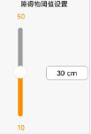 |
Adjust obstacle threshold, unit is cm. |
 |
Turn on/off ultrasonic RGB light. |
 |
Adjust ultrasonic RGB light color. |
 |
Adjust motor speed, the higher the value, the faster the motor speed. |
Note: Do not detect objects at close range for a long time