

 English
HCM111Z TE-B User Guide
Introduction
To help you to develop applications with Quectel HCM111Z TE-B conveniently, Quectel supplies corresponding development board HCM111Z TE-B to test the module. This document can help customers quickly understand HCM111Z TE-B interface specifications, RF characteristics,electrical and mechanical details and know how to use it.
Product Overview
HCM111Z TE-B is a Bluetooth development board with Arduino interface, it can be used separately for developing and debugging applications.
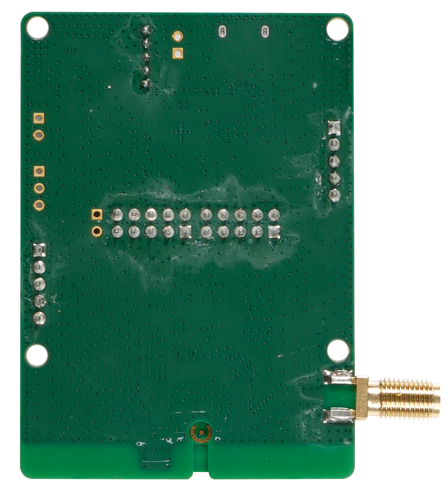
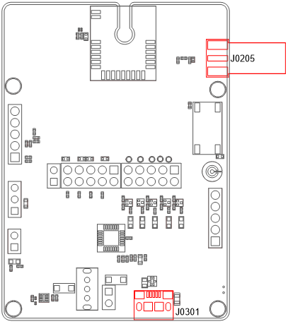
Top and Bottom Views
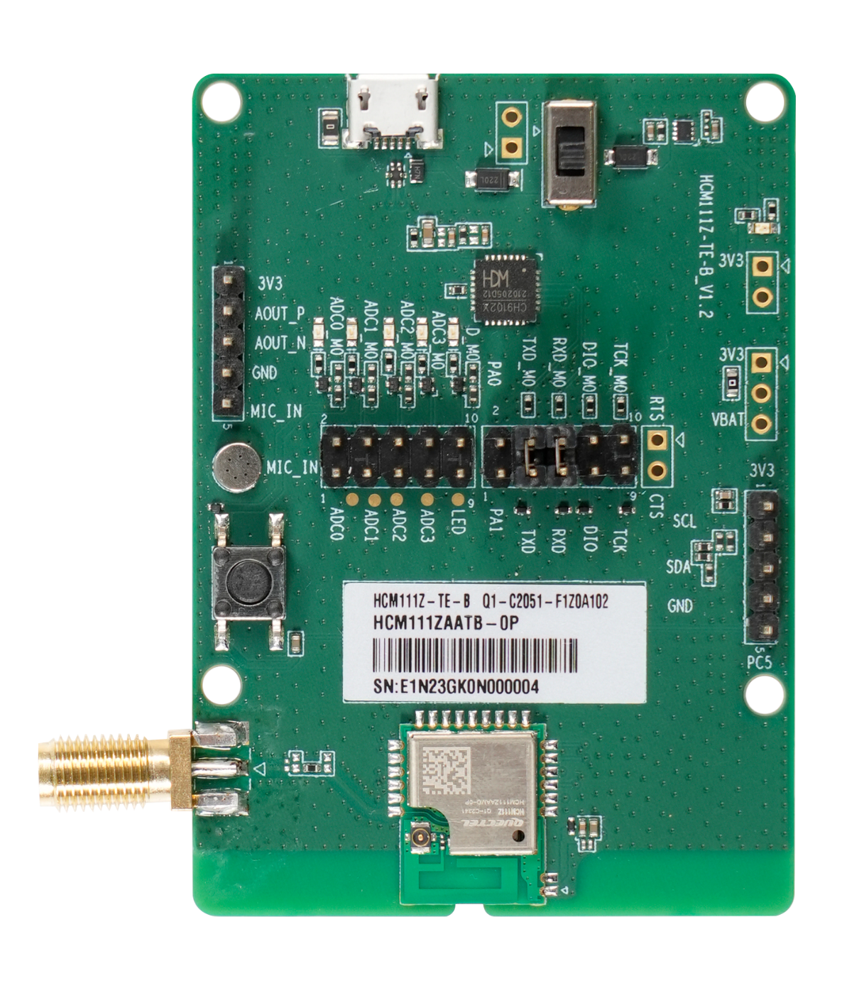
Component Placement
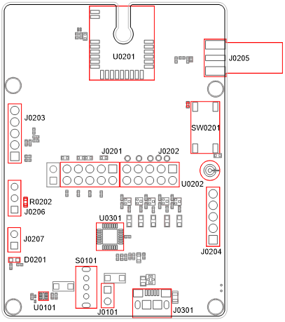
Component Information:
| Component | RefDes | Description | Comment |
|---|---|---|---|
| Power Supply Interfaces | J0301 | USB power supply interface | Typical supply voltage: +5 V |
| Power Supply Interfaces | J0101 | External power supply interface | Typical supply voltage: +5 V |
| Power Supply Interfaces | J0206 | External power supply interface | Typical supply voltage: +3.3 V |
| Power Switch | S0101 | VBAT on/off switch | - |
| Arduino | J0201, J0202, J0203, J0204 | Arduino standard interfaces | - |
| USB-to-UART Interface | J0202 | Connects to the UART interface of HCM111Z via USB-to-UART bridge U0301 | - |
| RF antenna interface | J0205 | RF SMA connector | - |
| Test Point | J0207 | Tests the basic functions of the module | - |
| ICs | U0101 | LDO | Convert the voltage from +5 V to +3.3 |
| ICs | U0301 | USB-to-UART Bridge | - |
| Bluetooth Module | U0201 | The HCM111Z module | - |
| MIC | U0202 | Microphone interface | - |
| RESET_N Button | SW0201 | Resets the module | - |
| Power Indicator | D0201 | Indicates the power supply on/off status | - |
| Resistor | R0202 | Tests the power consumption | - |
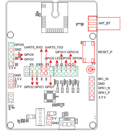
Arduino Interface Definition Diagram
Key Features
Key Features of TE-B:
| Parameters | Details |
|---|---|
| Power Supply | USB interface: Arduino interface: |
| Transmitting Power | 7.5 dBm ±2 dB |
| Temperature Range | |
| USB-to-UART Interface | 115200 bps baud rate by default transmission and firmware upgrade. |
| RESET_N Button | Resets the module |
| Size | (70 ±0.15) mm × (50 ±0.15) mm × (11.79 ±0.2) mm |
| Antenna interface | 50 Ω characteristic impedance |
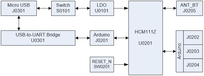
Functional Diagram
Application Interfaces
HCM111Z TE-B can be used alone to upgrade firmware and to debug applications based on HCM111Z TE-B. The following describes the operation procedures of TE-B in different operation modes.
Operation Procedure with Single Board
Interface Diagram of Using TE-B Alone
Operation Procedures of Using TE-B Alone
- Install USB-to-UART driver which can be downloaded from the following link:https://www.ftdichip.cn/Drivers/VCP.htm;
- Check the TXD, TXD_M0, RXD and RXD_M0 of the J0201 (Arduino interface) on the TE-B that whether them are connected with a jumper cap or not.
- Switch S0101 (power switch) to "ON".
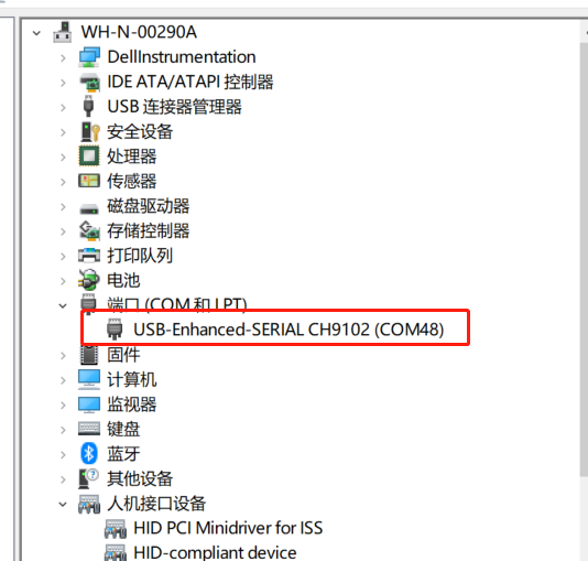
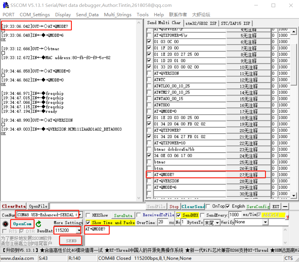
- Connect the J0301 (USB power supply interface) with PC via Micro-USB cable. Serial port information will be shown on "Device Manager"of PC. Among them, "USB-Enhanced-SERIAL CH9102 (COM48)"(corresponding to USB Serial Converter A) is connected to the main UART of HCM111Z TE-B, which can be used for AT command transmission,data transmission and firmware upgrade. For details of UART configuration, see document [1].
- Connect the J0201 (Arduino interface) and the relevant functional interface of the user motherboard PCB board for functional debugging. For details of Arduino Interface, see document[2].
Power Consumption Test Guide
Test Tools
The following are the equipment and tools needed for the power consumption test:
- HCM111Z TE-B
- DC power analyzer
- Wire, soldering iron, tin wire, and wire stripping pliers etc. to weld the power supply cord on TE-B.
This power consumption test guide is based on Keysight's N6705C DC power analyzer for testing.
Modify TE-B
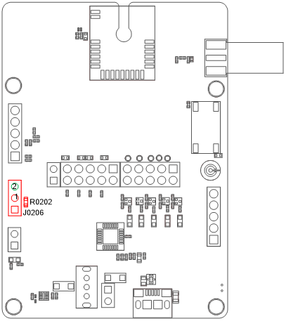
If you use the TE-B to test the power consumption of the HCM111Z, you need to modify the TE-B as follows:
- Remove R0202 (0 Ω resistor) to connect the USB power supply;
- Solder two wires to the two pins of J0206. One wire is used as VBAT(pin 1) and the other is used as GND (pin 2), so that the external power supply can supply power to the module separately.
Power Consumption Test Steps
Please refer to the following steps to test the current consumption of the module on the modified TE-B:
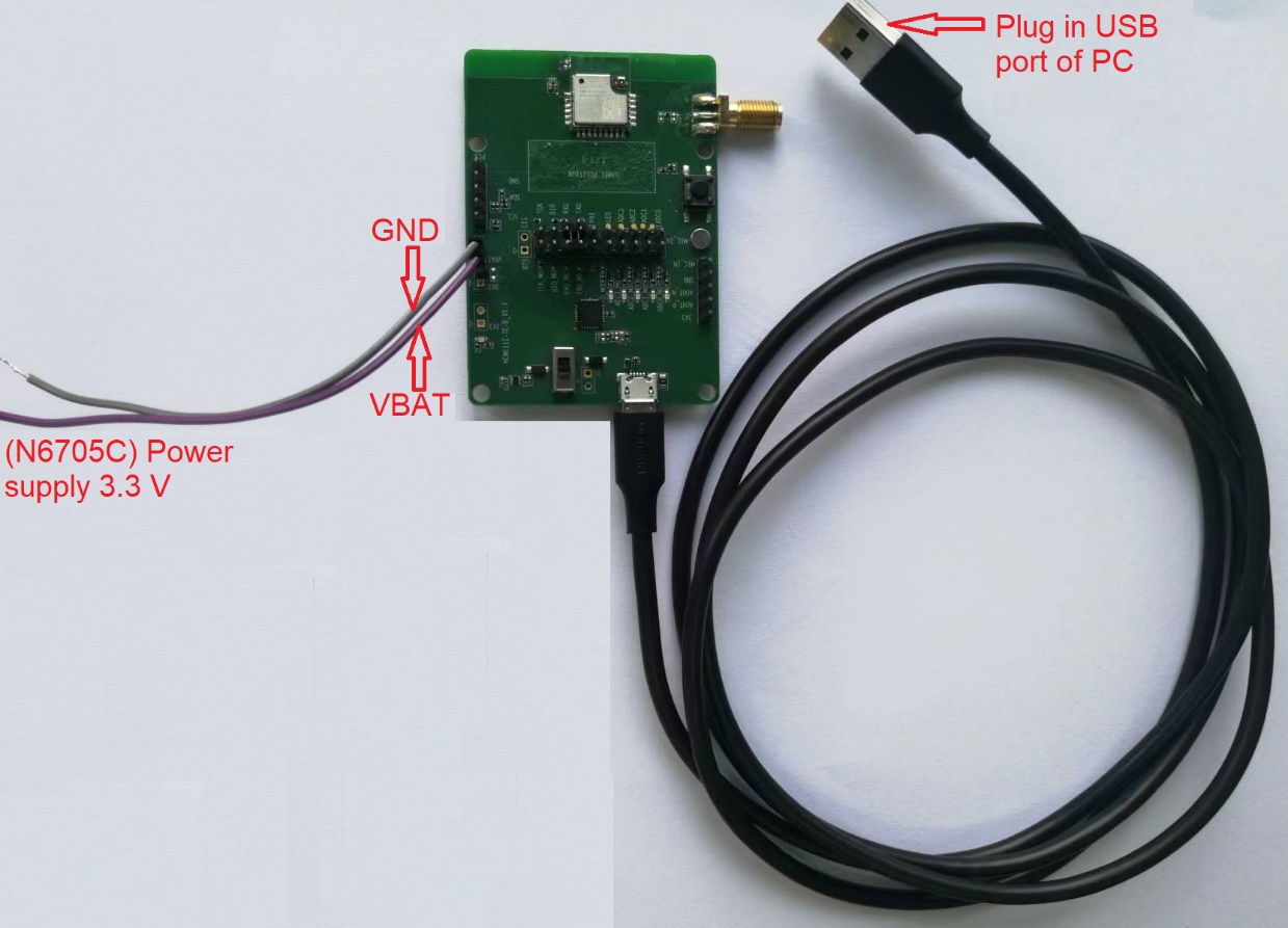
- Insert the USB cable.
- Set the output voltage on N6705C to 3.3 V, and connect the positive and negative wires of N6705C to the two wires (VBAT, GND) welded on J0206 to supply the module separately.
- Turn on the output voltage set by DC power analyzer N6705C, and the module will automatically turn on after powering on.
- Conduct power consumption tests in different modes.
Appendix References
Related Documents:
| Document Name |
|---|
| [1] Quectel_HCM111Z_AT Command |
| [2] Quectel_HCM111Z_Hardware Design |
Terms and AbbreviationsP:
| Abbreviation | Description |
|---|---|
| DC | Direct Current |
| GND | Ground |
| IC | Integrated Circuit |
| LDO | Low-dropout Regulator |
| MIC | Microphone |
| PC | Personal Computer |
| RF | Radio Frequency |
| RXD | Receive Data |
| SMA | Sub Miniature Version A |
| TXD | Transmit Data |
| UART | Universal Asynchronous Receiver & Transmitter |
| USB | Universal Serial Bus |
| VBAT | Voltage at Battery |
Within operating temperature range, the module is 3GPP compliant.↩