

 English
HCM111Z QuecOpen(SDK) Peripheral Interface Development Guide
Introduction
Quectel HCM111Z module supports QuecOpen® solution. QuecOpen® is an embedded development platform, which is intended to simplify the design and development of IoT applications.
This document is applicable to the QuecOpen® solution based on SDK build environment. It outlines how to use GPIO, PMU GPIO, UART, ADC, PWM, SPI and I2C APIs supported by the module to develop corresponding peripheral interfaces in QuecOpen® solution.
GPIO API
Header File
ql_gpio.h, the header file of GPIO API, is in the components/quectel_api/ql_include directory. Unless otherwise specified, all header files mentioned in this document are in this directory.
API Overview
| Function | Description |
|---|---|
ql_gpio_set_port_mux() |
Sets the GPIO multiplexing feature. |
ql_gpio_init() |
Initializes a GPIO pin. |
ql_gpio_set_level() |
Sets the level of the specified GPIO pin. |
ql_gpio_get_level() |
Gets the level of the specified GPIO pin. |
ql_gpio_int_init() |
Initializes and enables the GPIO interrupt. |
ql_gpio_int_disable() |
Disables the configured GPIO interrupt. |
ql_gpio_set_port_pull() |
Sets the pull-up mode when GPIO is used as an input port. |
API Description
ql_gpio_set_port_mux
This function sets the GPIO multiplexing feature.
Prototype:
ql_gpio_errcode_e ql_gpio_set_port_mux(ql_gpio_num_e pin, uint8_t func)
Parameters:
pin: [In] GPIO pin number. See ql_gpio_num_e.func: [In] GPIO multiplexing feature.
Return Value:
Function execution result code. See ql_gpio_errcode_e.
ql_gpio_init
This function initializes a GPIO pin.
Prototype:
ql_gpio_errcode_e ql_gpio_init(ql_gpio_num_e pin, ql_gpio_mode_e mode)
Parameters:
pin: [In] GPIO pin number. See ql_gpio_num_e.mode: [In] GPIO pin mode. See ql_gpio_mode_e.
Return Value:
Function execution result code. See ql_gpio_errcode_e.
ql_gpio_num_e
The enumeration of GPIO pin number:
typedef enum {
  QL_GPIO_PA0,
  QL_GPIO_PA1,
  QL_GPIO_PA2,
  QL_GPIO_PA3,
  QL_GPIO_PA4,
  QL_GPIO_PA5,
  QL_GPIO_PA6,
  QL_GPIO_PA7,
  QL_GPIO_PB0,
  QL_GPIO_PB1,
  QL_GPIO_PB2,
  QL_GPIO_PB3,
  QL_GPIO_PB4,
  QL_GPIO_PB5,
  QL_GPIO_PB6,
  QL_GPIO_PB7,
  QL_GPIO_PC0,
  QL_GPIO_PC1,
  QL_GPIO_PC2,
  QL_GPIO_PC3,
  QL_GPIO_PC4,
  QL_GPIO_PC5,
  QL_GPIO_PC6,
  QL_GPIO_PC7,
  QL_GPIO_PD0,
  QL_GPIO_PD1,
  QL_GPIO_PD2,
  QL_GPIO_PD3,
  QL_GPIO_PD4,
  QL_GPIO_PD5,
  QL_GPIO_PD6,
  QL_GPIO_PD7,
} ql_gpio_num_e
Member:
| Member | Description |
|---|---|
QL_GPIO_PA0 |
GPIOA0 |
QL_GPIO_PA1 |
GPIOA1 |
QL_GPIO_PA2 |
GPIOA2 |
QL_GPIO_PA3 |
GPIOA3 |
QL_GPIO_PA4 |
GPIOA4 |
QL_GPIO_PA5 |
GPIOA5 |
QL_GPIO_PA6 |
GPIOA6 |
QL_GPIO_PA7 |
GPIOA7 |
QL_GPIO_PB0 |
GPIOB0 |
QL_GPIO_PB1 |
GPIOB1 |
QL_GPIO_PB2 |
GPIOB2 |
QL_GPIO_PB3 |
GPIOB3 |
QL_GPIO_PB4 |
GPIOB4 |
QL_GPIO_PB5 |
GPIOB5 |
QL_GPIO_PB6 |
GPIOB6 |
QL_GPIO_PB7 |
GPIOB7 |
QL_GPIO_PC0 |
GPIOC0 |
QL_GPIO_PC1 |
GPIOC1 |
QL_GPIO_PC2 |
GPIOC2 |
QL_GPIO_PC3 |
GPIOC3 |
QL_GPIO_PC4 |
GPIOC4 |
QL_GPIO_PC5 |
GPIOC5 |
QL_GPIO_PC6 |
GPIOC6 |
QL_GPIO_PC7 |
GPIOC7 |
QL_GPIO_PD0 |
GPIOD0 |
QL_GPIO_PD1 |
GPIOD1 |
QL_GPIO_PD2 |
GPIOD2 |
QL_GPIO_PD3 |
GPIOD3 |
QL_GPIO_PD4 |
GPIOD4 |
QL_GPIO_PD5 |
GPIOD5 |
QL_GPIO_PD6 |
GPIOD6 |
QL_GPIO_PD7 |
GPIOD7 |
ql_gpio_mode_e
The enumeration of GPIO pin modes:
typedef enum {
  QL_GMODE_INPUT_PULLDOWN = 1,
  QL_GMODE_INPUT_PULLUP,
  QL_GMODE_OUTPUT = 0,
} ql_gpio_mode_e
Member:
| Member | Description |
|---|---|
QL_GMODE_INPUT_PULLDOWN |
Input is configured for pull-down |
QL_GMODE_INPUT_PULLUP |
Input is configured for pull-up |
QL_GMODE_OUTPUT |
Push-pull output |
ql_gpio_errcode_e
The enumeration of GPIO result codes:
typedef enum {
  QL_GPIO_SUCCESS = 0,
  QL_GPIO_EXECUTE_ERR,
  QL_GPIO_INVALID_PARAM_ERR,
  QL_GPIO_EXTI_LINE_CLASH_ERR,
} ql_gpio_errcode_e
Member:
| Member | Description |
|---|---|
QL_GPIO_SUCCESS |
Successful execution |
QL_GPIO_EXECUTE_ERR |
Failed execution |
QL_GPIO_INVALID_PARAM_ERR |
Invalid parameter |
QL_GPIO_EXTI_LINE_CLASH_ERR |
GPIO interrupt line configuration conflict |
ql_gpio_set_level
This function sets the level of the specified GPIO pin. It is valid only for output pins.
Prototype:
ql_gpio_errcode_e ql_gpio_set_level(ql_gpio_num_e pin, ql_gpio_output_level_e output_level)
Parameters:
pin: [In] GPIO pin number. See ql_gpio_num_e.output_level: [In] Level dedicated for output pins. See ql_gpio_output_level_e.
Return Value:
Function execution result code. See ql_gpio_errcode_e.
ql_gpio_output_level_e
The enumeration of the GPIO output levels:
typedef enum {
  QL_GPIO_OUTPUT_LOW,
  QL_GPIO_OUTPUT_HIGH,
} ql_gpio_output_level_e
Member:
| Member | Description |
|---|---|
QL_GPIO_OUTPUT_LOW |
Low level |
QL_GPIO_OUTPUT_HIGH |
High level |
ql_gpio_get_level
This function gets the level of the specified GPIO pin.
Prototype:
ql_gpio_errcode_e ql_gpio_get_level(ql_gpio_num_e pin, uint32_t *input_level)
Parameters:
pin: [In] GPIO pin number. See ql_gpio_num_e.input_level: [Out] GPIO pin level.
Return Value:
Function execution result code. See ql_gpio_errcode_e.
ql_gpio_int_init
This function initializes and enables the GPIO interrupt.
Prototype:
ql_gpio_errcode_e ql_gpio_int_init(ql_gpio_num_e pin, ql_gpio_irq_trigger_e trigger, ql_gpio_irq_callback callback)
Parameters:
pin: [In] GPIO pin number. See ql_gpio_num_e.trigger: [In] GPIO interrupt triggering mode. See ql_gpio_irq_trigger_e.callback: [In] GPIO interrupt callback function. See ql_gpio_irq_callback.
Return Value:
Function execution result code. See ql_gpio_errcode_e.
ql_gpio_irq_trigger_e
The enumeration of GPIO interrupt triggering modes:
typedef enum {
  QL_IRQ_TRIGGER_LOW_LEVEL,
  QL_IRQ_TRIGGER_HIGH_LEVEL,
  QL_IRQ_TRIGGER_RISING_EDGE,
  QL_IRQ_TRIGGER_FALLING_EDGE,
} ql_gpio_irq_trigger_e
Member:
| Member | Description |
|---|---|
QL_IRQ_TRIGGER_LOW_LEVEL |
GPIO interrupt triggered at low level |
QL_IRQ_TRIGGER_HIGH_LEVEL |
GPIO interrupt triggered at high level |
QL_IRQ_TRIGGER_RISING_EDGE |
GPIO interrupt triggered at rising edge |
QL_IRQ_TRIGGER_FALLING_EDGE |
GPIO interrupt triggered at falling edge |
ql_gpio_irq_callback
This is the callback function of GPIO interrupt.
Prototype:
typedef void (*ql_gpio_irq_callback)(void *arg, uint8_t line)
Parameters:
arg: [In] Pin for triggering the GPIO interrupt.line: [Out] Serial number of the external interrupt line that triggers the GPIO interrupt.
ql_gpio_int_disable
This function disables the configured GPIO interrupt.
Prototype:
ql_gpio_errcode_e ql_gpio_int_disable(ql_gpio_num_e pin)
Parameters:
pin: [In] GPIO pin number. See ql_gpio_num_e.
Return Value:
Function execution result code. See ql_gpio_errcode_e.
ql_gpio_set_port_pull
This function sets the pull-up mode when GPIO is used as an input port.
Prototype:
ql_gpio_errcode_e ql_gpio_set_port_pull(ql_gpio_num_e pin, uint8_t enable)
Parameters:
pin: [In] GPIO pin number. See ql_gpio_num_e.enable: [In] Set the pull-up mode.
True Enable the pull-up mode
False No setting
Return Value:
Function execution result code. See ql_gpio_errcode_e.
GPIO Development Process
This chapter describes how to use the above GPIO API to configure GPIO pins and perform basic debugging. QL_GPIO_PD4, QL_GPIO_PD5 and QL_GPIO_PD6 are used in the following examples by default.
GPIO Operation
The example of how to use the GPIO API is provided in the quectel_demo/ql_gpio_demo/code/ql_gpio_demo.c file in the module SDK. The related functions are described as follows:
demo_gpio(): Initializes a GPIO pin and enables the GPIO interruptql_gpio_irq_test(): This is the interrupt callback function. It can implement functionalities such as setting the GPIO pin level and disabling GPIO interrupts.
The example of using the GPIO API is as follows:
void demo_gpio(void)
{
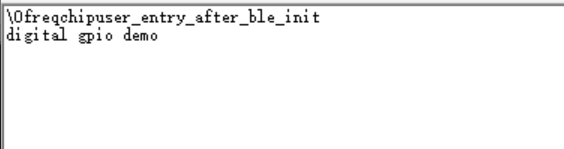
ql_debug("digital gpio demo\\r\\n");
//digital gpio output
ql_gpio_set_port_mux(QL_GPIO_PD4 , QL_PORTD4_FUNC_D4);
ql_gpio_set_port_mux(QL_GPIO_PD5 , QL_PORTD5_FUNC_D5);
ql_gpio_set_port_mux(QL_GPIO_PD6 , QL_PORTD6_FUNC_D6);
ql_gpio_init(QL_GPIO_PD4,QL_GMODE_OUTPUT);
ql_gpio_init(QL_GPIO_PD5,QL_GMODE_INPUT_PULLDOWN);
ql_gpio_set_level(QL_GPIO_PD4,QL_GPIO_OUTPUT_HIGH);
ql_gpio_init(QL_GPIO_PD6 , QL_GMODE_INPUT_PULLDOWN);
ql_gpio_int_init(QL_GPIO_PD6, QL_IRQ_TRIGGER_RISING_EDGE , ql_gpio_irq_test);
}
void ql_gpio_irq_test (void *arg,uint8_t line)
{
static int cnt = 0;
uint32_t input_level = 0;
ql_gpio_get_level(QL_GPIO_PD5,&input_level);
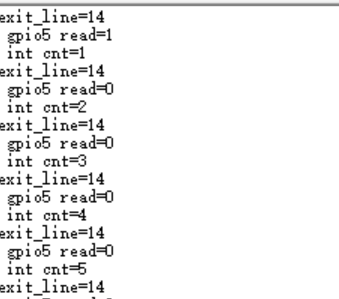
ql_debug("exit_line=%d\\r\\n",line);
ql_debug(" gpio5 read=%d\\r\\n",input_level);
if(input_level == 0){
ql_gpio_set_level(QL_GPIO_PD4,QL_GPIO_OUTPUT_LOW);
}else{
ql_gpio_set_level(QL_GPIO_PD4,QL_GPIO_OUTPUT_HIGH);
}
cnt++;
ql_debug(" int cnt=%d\\r\\n",cnt);
if(cnt >= 10){
ql_gpio_int_disable(QL_GPIO_PD6);
cnt = 0;
}
}
Function Debugging
To debug the GPIO function, use the development board (HCM111Z TE-B) with the module and follow these steps:
- Recompile the firmware version and flash it to the module.
- Reboot the module.
- Open UART port 1 to obtain the debugging logs. The log information will be displayed as follows:
If the following information is printed during the debugging, it indicates that the GPIO interrupt has been triggered.
PMU GPIO API
Header File
ql_pmu_gpio.h, the header file of PMU GPIO API, is in the components/quectel_api/ql_include directory. Unless otherwise specified, all header files mentioned in this document are in this directory.
The functional difference between GPIO and PMU GPIO pins is that the PMU GPIO pins can keep the output level unchanged when the module is in sleep state.
API Overview
| Function | Description |
|---|---|
ql_pmu_gpio_init() |
Initializes a PMU GPIO pin. |
ql_pmu_gpio_set_level() |
Sets the level of the specified PMU GPIO pin. |
ql_pmu_gpio_get_level() |
Gets the level of the specified PMU GPIO pin. |
ql_pmu_gpio_int_init() |
Initializes and enables the PMU GPIO interrupt. |
ql_pmu_gpio_int_disable() |
Disables the configured PMU GPIO interrupt. |
API Description
ql_pmu_gpio_init
This function initializes a PMU GPIO pin.
Prototype:
ql_gpio_errcode_e ql_pmu_gpio_init(ql_gpio_num_e pin, ql_gpio_mode_e mode)
Parameters:
pin: [In] PMU GPIO pin number. See ql_gpio_num_e.mode: [In] PMU GPIO mode. See ql_gpio_mode_e.
Return Value:
Function execution result code. See ql_gpio_errcode_e.
ql_pmu_gpio_set_level
This function sets the level of the specified PMU GPIO pin. It is valid only for output pins.
Prototype:
ql_gpio_errcode_e ql_pmu_gpio_set_level(ql_gpio_num_e pin, ql_gpio_output_level_e output_level)
Parameters:
pin: [In] PMU GPIO pin number. See ql_gpio_num_e.output_level: [In] Level dedicated for output pins. See ql_gpio_output_level_e.
Return Value:
Function execution result code. See ql_gpio_errcode_e.
ql_pmu_gpio_get_level
This function gets the level of the specified PMU GPIO pin.
Prototype:
ql_gpio_errcode_e ql_pmu_gpio_get_level(ql_gpio_num_e pin, uint32_t *input_level)
Parameters:
pin: [In] PMU GPIO pin number. See ql_gpio_num_e.input_level: [Out] PMU GPIO pin level.
Return Value:
Function execution result code. See ql_gpio_errcode_e.
ql_pmu_gpio_int_init
This function initializes and enables the PMU GPIO interrupt.
Prototype:
ql_gpio_errcode_e ql_pmu_gpio_int_init(ql_gpio_num_e pin, ql_gpio_irq_trigger_e trigger, ql_pmu_gpio_irq_callback callback)
Parameters:
pin: [In] PMU GPIO pin number. See ql_gpio_num_e.trigger: [In] PMU GPIO interrupt triggering mode. See ql_gpio_irq_trigger_e.callback: [In] PMU GPIO interrupt callback function. See ql_pmu_gpio_irq_callback.
Return Value:
Function execution result code. See ql_gpio_errcode_e.
ql_pmu_gpio_irq_callback
This is the callback function of PMU GPIO interrupt.
Prototype:
typedef void (*ql_pmu_gpio_irq_callback)(void *arg)
Parameters:
arg: [Out] Reserved.
ql_pmu_gpio_int_disable
This function disables the configured PMU GPIO interrupt.
Prototype:
ql_gpio_errcode_e ql_pmu_gpio_int_disable(ql_gpio_num_e pin)
Parameters:
pin: [In] PMU GPIO pin number. See ql_gpio_num_e.
Return Value:
Function execution result code. See ql_gpio_errcode_e.
PMU GPIO Development Process
This chapter describes how to use the above PMU GPIO API to configure PMU GPIO pins and perform basic debugging. QL_GPIO_PD4, QL_GPIO_PD5 and QL_GPIO_PD6 are used in the following examples by default.
PMU GPIO Operation
The example of how to use the PMU GPIO API is provided in the quectel_demo/ql_pmu_gpio_demo/code/ql_pmu_gpio_demo.c file in the module SDK. The related functions are described as follows:
demo_pmu_gpio(): Initializes PMU GPIO and enables the PMU GPIO interruptql_gpio_pmu_irq_test(): This is the interrupt callback function. It can implement the functionalities such as getting the pin level of PMU GPIO, setting the level of PMU GPIO pin and disabling the PMU GPIO interrupt.
The example of using the PMU GPIO API is as follows:
void demo_pmu_gpio(void)
{
ql_debug("pmu gpio demo\\r\\n");
ql_pmu_gpio_init(QL_GPIO_PD4,QL_GMODE_OUTPUT);
ql_pmu_gpio_init(QL_GPIO_PD5,QL_GMODE_INPUT_PULLDOWN);
ql_pmu_gpio_set_level(QL_GPIO_PD4,QL_GPIO_OUTPUT_HIGH);
ql_pmu_gpio_int_init(QL_GPIO_PD6, QL_IRQ_TRIGGER_FALLING_EDGE, ql_gpio_pmu_irq_test);//wakeup pin
}
void ql_gpio_pmu_irq_test (void *arg)
{
static int cnt = 0;
uint32_t input_level = 0;
ql_pmu_gpio_get_level(QL_GPIO_PD5,&input_level);
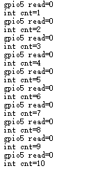
ql_debug(" gpio5 read=%d\\r\\n",input_level);
if(input_level == 0){
ql_pmu_gpio_set_level(QL_GPIO_PD4,QL_GPIO_OUTPUT_LOW);
}else{
ql_pmu_gpio_set_level(QL_GPIO_PD4,QL_GPIO_OUTPUT_HIGH);
}
cnt++;
ql_debug(" int cnt=%d\\r\\n",cnt);
if(cnt >= 10){
ql_pmu_gpio_int_disable(QL_GPIO_PD6);
cnt = 0;
}
}
Function Debugging
To debug the PMU GPIO function, use the development board (HCM111Z TE-B) with the module and follow these steps:
- Recompile the firmware version and flash it to the module.
- Reboot the module.
- Open UART port 1 to obtain the debugging logs. The log information will be displayed as follows:

If the following information is printed during the debugging, it indicates that the PMU GPIO interrupt has been triggered.
UART API
Header File
ql_uart.h, the header file of UART API, is in the components/quectel_api/ql_include directory. Unless otherwise specified, all header files mentioned in this document are in this directory.
API Overview
| Function | Description |
|---|---|
ql_uart_set_dcbconfig() |
Sets the UART port properties. |
ql_uart_get_dcbconfig() |
Gets the configuration of UART port properties. |
ql_uart_open() |
Opens the UART port. |
ql_uart_close() |
Closes the UART port. |
ql_uart_write() |
Writes data to the module through the UART port. |
ql_uart_read() |
Reads the data from the module through the UART port. |
ql_uart_set_rx_cb() |
Registers the callback function for UART data interrupt. |
API Description
ql_uart_set_dcbconfig
This function sets the UART port properties, which take effect after the UART port is re-opened.
Prototype:
ql_uart_errcode_e ql_uart_set_dcbconfig(ql_uart_port_number_e port, ql_uart_config_s *dcb)
Parameters:
port: [In] UART port number. See ql_uart_port_number_e.dcb: [In] Configuration of UART port properties. See ql_uart_config_s.
Return Value:
Function execution result code. See ql_uart_errcode_e.
ql_uart_port_number_e
The enumeration of the UART port number is defined below. The module currently supports two UART ports.
typedef enum {
  QL_UART_PORT_1,
  QL_UART_PORT_2,
} ql_uart_port_number_e
Member:
| Member | Description |
|---|---|
QL_UART_PORT_1 |
UART port 1 |
QL_UART_PORT_2 |
UART port 2 |
ql_uart_config_s
The structure of the configuration of UART port properties:
typedef struct {
  uint8_t is_debug_port;
  ql_uart_baud_e baudrate;
  ql_uart_databit_e data_bit;
  ql_uart_stopbit_e stop_bit;
  ql_uart_parityit_e parity_bit;
} ql_uart_config_s
Parameter:
| Type | Parameter | Description |
|---|---|---|
| uint8_t | is_debug_port |
Print log (0: Receive and send data) |
| ql_uart_baud_e | baudrate |
Baud rate. Default: 115200 bps.See ql_uart_baud_e |
| ql_uart_databit_e | data_bit |
Data bit. Default: 8 bits.See ql_uart_databit_e |
| ql_uart_stopbit_e | stop_bit |
Stop bit. Default: 1 bit.See ql_uart_stopbit_e |
| ql_uart_parityit_e | parity_bit |
Parity bit. Default: No parity bit.See ql_uart_parityit_e |
ql_uart_baud_e
The enumeration of baud rates:
typedef enum {
  QL_UART_BAUD_2400 = 2400,
  QL_UART_BAUD_4800 = 4800,
  QL_UART_BAUD_9600 = 9600,
  QL_UART_BAUD_14400 = 14400,
  QL_UART_BAUD_19200 = 19200,
  QL_UART_BAUD_38400 = 38400,
  QL_UART_BAUD_57600 = 57600,
  QL_UART_BAUD_115200 = 115200,
  QL_UART_BAUD_230400 = 230400,
  QL_UART_BAUD_460800 = 460800,
  QL_UART_BAUD_921600 = 921600,
} ql_uart_baud_e
Member:
| Member | Description |
|---|---|
QL_UART_BAUD_2400 |
2400 bps |
QL_UART_BAUD_4800 |
4800 bps |
QL_UART_BAUD_9600 |
9600 bps |
QL_UART_BAUD_14400 |
14400 bps |
QL_UART_BAUD_19200 |
19200 bps |
QL_UART_BAUD_38400 |
38400 bps |
QL_UART_BAUD_57600 |
57600 bps |
QL_UART_BAUD_115200 |
115200 bps |
QL_UART_BAUD_230400 |
230400 bps |
QL_UART_BAUD_460800 |
460800 bps |
QL_UART_BAUD_921600 |
921600 bps |
ql_uart_databit_e
The enumeration of data bits:
typedef enum {
  QL_UART_DATABIT_5,
  QL_UART_DATABIT_6,
  QL_UART_DATABIT_7,
  QL_UART_DATABIT_8,
} ql_uart_databit_e
Member:
| Member | Description |
|---|---|
QL_UART_DATABIT_5 |
5 bits |
QL_UART_DATABIT_6 |
6 bits |
QL_UART_DATABIT_7 |
7 bits |
QL_UART_DATABIT_8 |
8 bits |
ql_uart_stopbit_e
The enumeration of stop bits:
typedef enum {
  QL_UART_STOP_1,
  QL_UART_STOP_2,
} ql_uart_stopbit_e
Member:
| Member | Description |
|---|---|
QL_UART_STOP_1 |
1 bit |
QL_UART_STOP_2 |
2 bits |
ql_uart_parityit_e
The enumeration of parity bits:
typedef enum {
  QL_UART_PARITY_NONE,
  QL_UART_PARITY_ODD,
  QL_UART_PARITY_EVEN,
} ql_uart_parityit_e
Member:
| Member | Description |
|---|---|
QL_UART_PARITY_NONE |
No parity |
QL_UART_PARITY_ODD |
Odd parity |
QL_UART_PARITY_EVEN |
Even parity |
ql_uart_errcode_e
The enumeration of UART result codes:
typedef enum {
  QL_UART_SUCCESS = 0,
  QL_UART_EXECUTE_ERR,
  QL_UART_MEM_ADDR_NULL_ERR,
  QL_UART_INVALID_PARAM_ERR,
  QL_UART_NOT_OPEN_ERR,
} ql_uart_errcode_e
Member:
| Member | Description |
|---|---|
QL_UART_SUCCESS |
Successful execution |
QL_UART_EXECUTE_ERR |
Failed execution |
QL_UART_MEM_ADDR_NULL_ERR |
Parameter address is null |
QL_UART_INVALID_PARAM_ERR |
Invalid parameter |
QL_UART_NOT_OPEN_ERR |
UART port is not open |
ql_uart_get_dcbconfig
This function gets the configuration of UART port properties.
Prototype:
ql_uart_errcode_e ql_uart_get_dcbconfig(ql_uart_port_number_e port, ql_uart_config_s *dcb)
Parameters:
port: [In] UART port number. See ql_uart_port_number_e.dcb: [In] Configuration of UART port properties. See ql_uart_config_s.
Return Value:
Function execution result code. See ql_uart_errcode_e.
ql_uart_open
This function opens the UART port.
Prototype:
ql_uart_errcode_e ql_uart_open(ql_uart_port_number_e port)
Parameters:
port: [In] UART port number. See ql_uart_port_number_e.
Return Value:
Function execution result code. See ql_uart_errcode_e.
ql_uart_close
This function closes the UART port.
Prototype:
ql_uart_errcode_e ql_uart_close(ql_uart_port_number_e port)
Parameters:
port: [In] UART port number. See ql_uart_port_number_e.
Return Value:
Function execution result code. See ql_uart_errcode_e.
ql_uart_write
This function writes data to the module through the UART port.
Prototype:
int ql_uart_write(ql_uart_port_number_e port, unsigned char *data, unsigned int data_len)
Parameters:
port: [In] UART port number. See ql_uart_port_number_e.data: [In] Written data.data_len: [In] Length of written data.
Return Value:
Function execution result code. See ql_uart_errcode_e.
ql_uart_read
This function reads the data from the module through the UART port.
Prototype:
int ql_uart_read(ql_uart_port_number_e port, unsigned char *data, unsigned int data_len)
Parameters:
port: [In] UART port number. See ql_uart_port_number_e.data: [Out] Read data.data_len: [In] Length of read data.
Return Value:
Function execution result code. See ql_uart_errcode_e.
ql_uart_set_rx_cb
This function registers the callback function that is triggered when a data interrupt is received via the UART port.
Prototype:
ql_uart_errcode_e ql_uart_set_rx_cb(ql_uart_port_number_e port, ql_uart_callback uart_cb)
Parameters:
port: [In] UART port number. See ql_uart_port_number_e.uart_cb: [In] Callback function to be registered. See ql_uart_callback.
Return Value:
Function execution result code. See ql_uart_errcode_e.
ql_uart_callback
This is the callback function that handles the UART interrupt.
Prototype:
typedef void (*ql_uart_callback)(char value)
Parameters:
value: [In] Data received via the UART port.
Return Value:
None
UART Development Process
This chapter describes how to use the above UART API in the application and perform basic debugging. UART 0 is used in the following example by default.
UART Operation
The example of how to use the UART API is provided in the quectel_demo/ql_uart_demo/code/ql_uart_demo.c file in the module SDK. The related functions are described as follows:
demo_uart(): Initializes the UART port and registers the interrupt callback function.ql_uart_cb_test(): Interrupt callback function that handles the data received through the UART port.
The example of using the UART API is as follows:
void demo_uart(void)
{
ql_uart_config_s cfg = {
.is_debug_port = 0, //0 | 1
.baudrate = QL_UART_BAUD_115200,
.data_bit = QL_UART_DATABIT_8,
.stop_bit = QL_UART_STOP_1,
.parity_bit = QL_UART_PARITY_NONE,
};
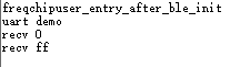
ql_debug("uart demo\\r\\n");
ql_gpio_set_port_mux(QL_GPIO_PD4,QL_PORTD4_FUNC_UART0_RXD);
ql_gpio_set_port_mux(QL_GPIO_PD5,QL_PORTD5_FUNC_UART0_TXD);
ql_gpio_set_port_pull(QL_GPIO_PD4, true);
ql_uart_set_dcbconfig(QL_UART_PORT_0,&cfg);
ql_uart_set_rx_cb(QL_UART_PORT_0,ql_uart_cb_test);
ql_uart_open(QL_UART_PORT_0);
}
void ql_uart_cb_test(char value)
{
char data = value;
ql_debug("recv %0x\\r\\n",data);
ql_uart_write(QL_UART_PORT_0,(unsigned char*)&data,1);
}
Function Debugging
To debug the UART function, use the development board (HCM111Z TE-B) with the module and follow these steps:
- Recompile the firmware version and flash it to the module.
- Reboot the module.
- Open UART port 1 to obtain the debugging logs. The log information will be displayed as follows:
ADC API
Header File
ql_adc.h, the header file of ADC API, is in the components/quectel_api/ql_include directory. Unless otherwise specified, all header files mentioned in this document are in this directory.
API Overview
| Function | Description |
|---|---|
ql_adc_channel_init() |
Configures ADC channel parameters. |
ql_adc_channel_start() |
Enables ADC channel detection. |
ql_adc_channel_stop() |
Disables ADC channel detection. |
API Description
ql_adc_channel_init
This function configures ADC channel parameters.
Prototype:
ql_adc_errcode_e ql_adc_channel_init(ql_adc_obj_s *handle, ql_adc_obj_callback cb, ql_adc_channel_e channel, void *user_data)
Parameters:
handle: [In] ADC channel. See ql_adc_obj_s.cb: [In] Callback function for ADC channel detection. See ql_adc_obj_callback.channel: [In] ADC channel number. See ql_adc_channel_e.user_data: [In] User data.
Return Value:
Function execution result code. See ql_adc_errcode_e.
ql_adc_obj_s
The structure of ADC channels:
typedef struct adc_obj_ {
  void *user_data;
  ql_adc_channel_e channel;
  ql_adc_obj_callback cb;
  struct adc_obj_ *next;
} ql_adc_obj_s
Parameter:
| Type | Parameter | Description |
|---|---|---|
| void | user_data |
User data. |
| ql_adc_channel_e | channel |
ADC channel number. |
| ql_adc_obj_callback | cb |
Callback function for channel detection. |
| struct adc_obj_ | next |
Address of the next node in the Linked List. |
ql_adc_obj_callback
This function is the callback function for ADC channel detection.
Prototype:
typedef void (*ql_adc_obj_callback)(ql_adc_channel_e channel, int value, void *user_data)
Parameters:
channel: [Out] ADC channel number. See ql_adc_channel_e.value: [In] ADC channel voltage sampling result. Range: 0--1023. Reference voltage: 3.3 V. When the sampling result is 1023, it means that the channel voltage is greater than or equal to 3.3 V.user_data: [In] User data.
Return Value:
None
ql_adc_channel_e
The enumeration of ADC channel number.
typedef enum {
  QL_ADC_CHANNEL_0 = 0x01,
  QL_ADC_CHANNEL_1 = 0x02,
  QL_ADC_CHANNEL_2 = 0x04,
  QL_ADC_CHANNEL_3 = 0x08,
} ql_adc_channel_e
Parameter:
| Parameter | Description |
|---|---|
QL_ADC_CHANNEL_0 |
Channel 0, detecting voltage for QL_GPIO_PD4. |
QL_ADC_CHANNEL_1 |
Channel 1, detecting voltage for QL_GPIO_PD5. |
QL_ADC_CHANNEL_2 |
Channel 2, detecting voltage for QL_GPIO_PD6. |
QL_ADC_CHANNEL_3 |
Channel 3, detecting voltage for QL_GPIO_PD7. |
ql_adc_errcode_e
The enumeration of ADC result codes:
typedef enum {
  QL_ADC_SUCCESS = 0,
  QL_ADC_EXECUTE_ERR,
  QL_ADC_INVALID_PARAM_ERR,
} ql_adc_errcode_e
Parameter:
| Parameter | Description |
|---|---|
QL_ADC_SUCCESS |
Successful execution |
QL_ADC_EXECUTE_ERR |
Failed execution |
QL_ADC_INVALID_PARAM_ERR |
Invalid parameter |
ql_adc_channel_start
This function enables ADC channel detection.
Prototype:
ql_adc_errcode_e ql_adc_channel_start(ql_adc_obj_s *handle)
Parameters:
handle: [In] ADC channel. See ql_adc_obj_s.
Return Value:
Function execution result code. See ql_adc_errcode_e.
ql_adc_channel_stop
This function disables ADC channel detection.
Prototype:
ql_adc_errcode_e ql_adc_channel_stop(ql_adc_obj_s *handle)
Parameters:
handle: [In] ADC channel. See ql_adc_obj_s.
Return Value:
Function execution result code. See ql_adc_errcode_e.
ADC Development Process
This chapter describes how to use the above ADC API in the application, and perform basic debugging. In the example, channel 0 is used for test by default.
ADC Operation
The example of how to use the ADC API is provided in the quectel_demo/ql_adc_demo/code/ql_adc_demo.c file the module SDK. The related functions are described as follows:
demo_adc(): Configure and initialize ADC channels.adc_tim_fn(): The timer callback function, which implements ADC channel detection every 1 s.
The example of using ADC API is as follows:
void demo_adc(void)
{
    ql_debug("adc demo\\r\\n");
    ql_gpio_set_port_mux(QL_GPIO_PD4,QL_PORTD4_FUNC_ADC0);
    ql_soft_timer_init(&adc_timer , adc_tim_fn , NULL);
    ql_soft_timer_start(&adc_timer,1000,1);
}
void adc_tim_fn(void *arg)
{
    ql_adc_channel_init(&ql_test_adc , ql_adc_detect_callback , QL_ADC_CHANNEL_0 , NULL);
    ql_adc_channel_start(&ql_test_adc);
    ql_adc_channel_stop(&ql_test_adc);
}
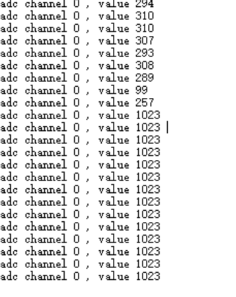
You can print the result of ADC channel detection through ql_adc_detect_callback() as follows:
static void ql_adc_detect_callback(ql_adc_channel_e channel, int value , void *user_data)
{
    ql_debug("adc channel %d , value %d \\r\\n" , channel , value);
}
Function Debugging
To debug the ADC function, use the development board (HCM111Z TE-B) with the module and follow these steps:
- Recompile the firmware version and flash it to the module.
- Reboot the module.
- Open UART port 1 to obtain the debugging logs. Change the input voltage of the pin and the detection value changes accordingly. The log information will be displayed as follows:
PWM API
Header File
ql_pwm.h, the header file of PWM API, is in the components/quectel_api/ql_include directory. Unless otherwise specified, all header files mentioned in this document are in this directory.
API Overview
| Function | Description |
|---|---|
ql_pwm_init() |
Initializes PWM. |
ql_pwm_update_param() |
Updates the PWM parameters. |
ql_pwm_enable() |
Enables PWM output. |
ql_pwm_disable() |
Disables PWM output. |
API Description
ql_pwm_init
This function initializes PWM.
Prototype:
ql_pwm_errcode_e ql_pwm_init(ql_pwm_channel_e channel, uint32_t frequency, uint32_t high_duty)
Parameters:
channel: [In] PWM channel. See ql_pwm_channel_e.frequency: [In] PWM frequency.high_duty: [In] PWM duty cycle.
Return Value:
Function execution result code. See ql_pwm_errcode_e.
ql_pwm_channel_e
The enumeration of PWM channels. There are 6 PWM channels in total.
typedef enum {
  QL_PWM_0 = 0,
  QL_PWM_1,
  QL_PWM_2,
  QL_PWM_3,
  QL_PWM_4,
  QL_PWM_5,
} ql_pwm_channel_e
Member:
| Member | Description |
|---|---|
QL_PWM_0 |
PWM 0 |
QL_PWM_1 |
PWM 1 |
QL_PWM_2 |
PWM 2 |
QL_PWM_3 |
PWM 3 |
QL_PWM_4 |
PWM 4 |
QL_PWM_5 |
PWM 5 |
ql_pwm_errcode_e
The enumeration of PWM result codes:
typedef enum {
  QL_PWM_SUCCESS = 0,
  QL_PWM_EXECUTE_ERR,
  QL_PWM_INVALID_PARAM_ERR,
} ql_pwm_errcode_e
Member:
| Member | Description |
|---|---|
QL_PWM_SUCCESS |
Successful execution |
QL_PWM_EXECUTE_ERR |
Failed execution |
QL_PWM_INVALID_PARAM_ERR |
Invalid parameter |
ql_pwm_update_param
This function updates the PWM parameters. The updated parameters take effect in next PWM period.
Prototype:
ql_pwm_errcode_e ql_pwm_update_param(ql_pwm_channel_e channel, uint32_t frequency, uint32_t high_duty)
Parameters:
channel: [In] PWM channel. See ql_pwm_channel_e.frequency: [In] PWM frequency.high_duty: [In] PWM duty cycle.
Return Value:
Function execution result code. See ql_pwm_errcode_e.
ql_pwm_enable
This function enables PWM output.
Prototype:
ql_pwm_errcode_e ql_pwm_enable(ql_pwm_channel_e channel)
Parameters:
channel: [In] PWM channel. See ql_pwm_channel_e.
Return Value:
Function execution result code. See ql_pwm_errcode_e.
ql_pwm_disable
This function disables PWM output.
Prototype:
ql_pwm_errcode_e ql_pwm_disable(ql_pwm_channel_e channel)
Parameters:
channel: [In] PWM channel. See ql_pwm_channel_e.
Return Value:
Function execution result code. See ql_pwm_errcode_e.
PWM Development Process
This chapter describes how to use the above PWM API in the application, and perform simple debugging. In the example, QL_PWM_4 and QL_PWM_5 are used for test by default.
PWM Operation
The example of how to use the PWM API is provided in the quectel_demo/ql_pwm_demo/code/ql_pwm_demo.c file in the module SDK. The related functions are described as follows:
demo_pwm(): Initializes PWM, enables PWM output and disables PWM output.
The example of using PWM API is as follows:
void demo_pwm(void)
{
ql_debug("digital_pwm demo\\r\\n");
ql_gpio_set_port_mux(QL_GPIO_PD4,QL_PORTD4_FUNC_PWM4);
ql_gpio_set_port_mux(QL_GPIO_PD5,QL_PORTD5_FUNC_PWM5);
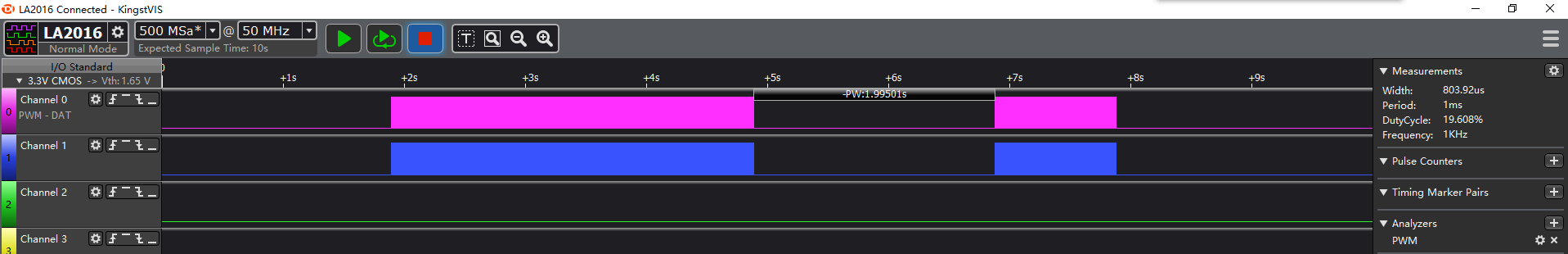
ql_pwm_init(QL_PWM_4,1000,50);
ql_pwm_init(QL_PWM_5,1000,80);
ql_pwm_enable(QL_PWM_4);
ql_pwm_enable(QL_PWM_5);
ql_sys_delay_100us(20000); //1 kHz for 2 s
ql_pwm_update_param(QL_PWM_4,10000,80);
ql_pwm_update_param(QL_PWM_5,10000,50);
ql_sys_delay_100us(10000); //10K Hz for 1 s
ql_pwm_disable(QL_PWM_4);
ql_pwm_disable(QL_PWM_5);
ql_sys_delay_100us(20000); //Stop for 2 s
ql_pwm_enable(QL_PWM_4);
ql_pwm_enable(QL_PWM_5);
ql_sys_delay_100us(10000); //Restart PWM with 10 kHz for 1 s
ql_pwm_disable(QL_PWM_4);
ql_pwm_disable(QL_PWM_5);
}
Function Debugging
To debug the PWM function use the development board (HCM111Z TE-B) with the module and follow these steps:
- Recompile the firmware version and flash it to the module.
- Reboot the module.
- Open UART port 1 to obtain the debugging logs. The log information will be displayed as follows:

SPI API
Header File
ql_spi.h, the header file of SPI API, is in the components/quectel_api/ql_include directory. Unless otherwise specified, all header files mentioned in this document are in this directory.
API Overview
| Function | Description |
|---|---|
ql_spi_init() |
Initializes SPI. |
ql_spi_transfer() |
Sends or receives SPI data. |
API Description
ql_spi_init
This function initializes SPI.
Prototype:
ql_spi_errcode_e ql_spi_init(ql_spi_config_s spi_cfg)
Parameters:
spi_cfg: [In] SPI configuration. See ql_spi_config_s.
Return Value:
Function execution result code. See ql_spi_errcode_e.
ql_spi_config_s
The structure of SPI configuration:
typedef struct {
  uint32_t spiclk;
  ql_spi_cpol_pol_e cpol;
  ql_spi_cpha_pol_e cpha;
  ql_spi_master_slave_mode_e masterorslave;
  void (*spi_cs_ctrl)(uint8_t);
} ql_spi_config_s
Parameter:
| Type | Parameter | Description |
|---|---|---|
| uint32_t | spiclk |
SPI clock frequency. Maximum value: 24 MHz. |
| ql_spi_cpol_pol_e | cpol |
SPI clock polarity.See ql_spi_cpol_pol_e. |
| ql_spi_cpha_pol_e | cpha |
SPI clock phase.See ql_spi_cpha_pol_e. |
| ql_spi_master_slave_mode_e | masterorslave |
SPI master or slave selection.See ql_spi_master_slave_mode_e. |
| void (*spi_cs_ctrl)(uint8_t) | spi_cs_ctrl |
Function pointer for controlling CS pin.See ql_spi_cs_ctrl() in SPI Operation. |
ql_spi_cpol_pol_e
The enumeration of SPI clock polarities:
typedef enum {
  QL_SPI_CPOL_LOW = 0,
  QL_SPI_CPOL_HIGH,
} ql_spi_cpol_pol_e
Member:
| Member | Description |
|---|---|
QL_SPI_CPOL_LOW |
SCK is at a low level during the idle state. |
QL_SPI_CPOL_HIGH |
SCK is at a high level during the idle state. |
ql_spi_cpha_pol_e
The enumeration of SPI clock phases:
typedef enum {
  QL_SPI_CPHA_1Edge,
  QL_SPI_CPHA_2Edge,
} ql_spi_cpha_pol_e
Member:
| Member | Description |
|---|---|
QL_SPI_CPHA_1Edge |
Sample data on the edge of the first period of SCK. |
QL_SPI_CPHA_2Edge |
Sample data on the edge of the second period of SCK. |
ql_spi_master_slave_mode_e
The enumeration of SPI master or slave selections:
typedef enum {
  QL_SPI_MASTER = 0,
  QL_SPI_SLAVE,
} ql_spi_master_slave_mode_e
Member:
| Member | Description |
|---|---|
QL_SPI_MASTER |
SPI serves as the master. |
QL_SPI_SLAVE |
SPI serves as the slave (Currently not supported). |
ql_spi_errcode_e
The enumeration of SPI result codes:
typedef enum {
  QL_SPI_SUCCESS = 0,
  QL_SPI_EXECUTE_ERR,
  QL_SPI_INVALID_PARAM_ERR,
} ql_spi_errcode_e
Member:
| Member | Description |
|---|---|
QL_SPI_SUCCESS |
Successful execution |
QL_SPI_EXECUTE_ERR |
Failed execution |
QL_SPI_INVALID_PARAM_ERR |
Invalid parameter |
ql_spi_transfer
This function sends or receives SPI data.
Prototype:
ql_errcode_spi_e ql_spi_transfer(ql_spi_messag_s *spi_msg)
Parameters:
spi_msg: [In] Data sent or received via SPI. See ql_spi_messag_s.
Return Value:
Function execution result code. See ql_spi_errcode_e.
ql_spi_messag_s
The structure of data sent or received via SPI:
typedef struct {
  UINT8 *send_buf;
  UINT32 send_len;
  UINT8 *recv_buf;
  UINT32 recv_len;
} ql_spi_message_s
Parameter:
| Type | Parameter | Description |
|---|---|---|
| UINT8 | send_buf |
Sent data |
| UINT32 | send_len |
Length of the sent data |
| UINT8 | recv_buf |
Received data |
| UINT32 | recv_len |
Length of the received data |
SPI Development Process
This chapter describes how to use the above SPI API in the application, and perform basic debugging.
SPI Operation
The example of how to use the SPI API is provided in the quectel_demo/ql_spi_demo/code/ql_spi_demo.c file in the module SDK. The related functions are described as follows:
demo_spi_master(): Initializes SPI, sends and receives data.ql_spi_cs_ctrl(): Controls CS pin.
The example of using SPI API is as follows:
void demo_spi_master(void)
{
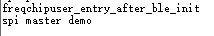
ql_debug("spi master demo\\r\\n");
uint8_t send_buff[128] = {0};
uint8_t recv_buff[128] = {0};
int i = 0;
for(i=0;i<128;i++)
send_buff[i] = i;
ql_spi_config_s cfg = {
.spiclk = 3000000,
.cpol = QL_SPI_CPOL_LOW,
.cpha = QL_SPI_CHPA_1EDGE,
.masterorslave = QL_SPI_MASTER,
.spi_cs_ctrl = ql_spi_cs_ctrl,
};
ql_spi_message_s msg = {
.send_buf = send_buff,
.send_len = 128,
.recv_buf = recv_buff,
.recv_len = 128,
};
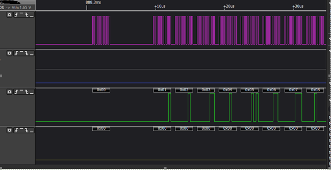
ql_gpio_set_port_mux(QL_GPIO_PD4, QL_PORTD4_FUNC_SSP0_CLK);
//ql_gpio_set_port_mux(QL_GPIO_PD5, QL_PORTD5_FUNC_SSP0_CSN);
ql_gpio_set_port_mux(QL_GPIO_PD5, QL_PORTD5_FUNC_D5);
ql_gpio_init(QL_GPIO_PD5,QL_GMODE_OUTPUT);
ql_gpio_set_port_mux(QL_GPIO_PD6, QL_PORTD6_FUNC_SSP0_DOUT);
ql_gpio_set_port_mux(QL_GPIO_PD7, QL_PORTD7_FUNC_SSP0_DIN);
ql_spi_init(cfg);
ql_spi_transfer(&msg);
ql_debug("spi master demo over\\r\\n");
}
void ql_spi_cs_ctrl(uint8_t enable)
{
ql_gpio_set_level(QL_GPIO_PD5,enable);
}
Function Debugging
To debug the SPI function, use the development board (HCM111Z TE-B) with the module and follow these steps:
- Recompile the firmware version and flash it to the module.
- Reboot the module.
- Open UART port 1 to obtain the debugging logs. The log information will be displayed as follows:
I2C API
Header File
ql_i2c.h, the header file of I2C API, is in the components/quectel_api/ql_include directory. Unless otherwise specified, all I2C header files mentioned in this document are in this directory.
API Overview
| Function | Description |
|---|---|
ql_i2c_init() |
Initializes the I2C bus. |
ql_i2c_write() |
Writes data to the I2C bus. |
ql_i2c_read() |
Reads data from the I2C bus. |
ql_i2c_master_init() |
Initializes the I2C master. |
ql_i2c_master_transmit() |
Transmits data from I2C master to the slave. |
ql_i2c_master_receive() |
Reads the data transmitted from I2C slave by I2C master. |
ql_i2c_slave_init() |
Initializes the I2C slave. |
ql_i2c_slave_transmit() |
Transmits data from I2C slave to I2C master. |
ql_i2c_slave_receive() |
Reads the data transmitted from I2C master by I2C slave. |
API Description
ql_i2c_init
This function initializes the I2C bus.
Prototype:
ql_errcode_i2c_e ql_i2c_init(QL_DD_HANDLE *i2c_hdl, ql_i2c_mode mode, ql_i2c_channel_e channel)
Parameters:
i2c_hdl: [Out] Obtained I2C handle.mode: [In] I2C bus operating mode. See ql_i2c_mode_e.channel: [In] I2C channel. See ql_i2c_channel_e.
Return Value:
Function execution result code. See ql_errcode_i2c_e.
ql_i2c_mode_e
The enumeration of I2C bus operating modes:
typedef enum {
  STANDARD_MODE = 0,
  FAST_MODE = 1,
} ql_i2c_mode_e
Member:
| Member | Description |
|---|---|
QL_STANDARD_MODE |
Standard mode |
FAST_MODE |
Fast mode |
ql_i2c_channel_e
The enumeration of I2C channels:
typedef enum {
  QL_I2C_CHANNEL_0 = 0,
  QL_I2C_CHANNEL_1,
} ql_i2c_channel_e
Member:
| Member | Description |
|---|---|
QL_I2C_CHANNEL_0 |
I2C channel 0 |
QL_I2C_CHANNEL_1 |
I2C channel 1 |
ql_errcode_i2c_e
The enumeration of the I2C result codes:
typedef enum {
  QL_I2C_SUCCESS = 0,
  QL_I2C_INIT_ERR,
  QL_I2C_WRITE_ERR,
  QL_I2C_READ_ERR,
} ql_errcode_i2c_e
Member:
| Member | Description |
|---|---|
QL_I2C_SUCCESS |
Successful execution |
QL_I2C_INIT_ERR |
Failed I2C initialization |
QL_I2C_WRITE_ERR |
Failed to write data to I2C |
QL_I2C_READ_ERR |
Failed to read data from I2C |
ql_i2c_write
This function writes data to the I2C bus.
Prototype:
ql_errcode_i2c_e ql_i2c_write(QL_DD_HANDLE *i2c_hdl, uint8_t slave_addr, uint8_t reg_addr, char *data, uint32_t len)
Parameters:
i2c_hdl: [In] I2C handle.slave_addr: [In] I2C slave device address.reg_addr: [In] I2C slave register address.data: [In] Data to be written to the I2C bus.len: [In] Data length to be written to the I2C bus.
Return Value:
Function execution result code. See ql_errcode_i2c_e.
ql_i2c_read
This function reads data from the I2C bus.
Prototype:
ql_errcode_i2c_e ql_i2c_read(QL_DD_HANDLE *i2c_hdl, uint8_t slave_addr, uint8_t reg_addr, char *data, uint32_t len)
Parameters:
i2c_hdl: [In] I2C handle.slave_addr: [In] I2C slave device address.reg_addr: [In] I2C slave register address.data: [Out] Data read from the I2C bus.len: [In] Data length read from the I2C bus.
Return Value:
Function execution result code. See ql_errcode_i2c_e.
ql_i2c_master_init
This function initializes the I2C master.
Prototype:
ql_errcode_i2c_e ql_i2c_master_init(ql_i2c_channel_e i2c_channel, ql_i2c_mode i2c_mode, ql_i2c_pin_mux_e pin_mux)
Parameters:
i2c_channel: [In] I2C channel. Only QL_I2C_CHANNEL_1 is supported.i2c_mode: [In] Working mode of I2C.pin_mux: [In] Multiplexed GPIO combination of I2C's SCL and SDA. See ql_i2c_pin_mux_e.
Return Value:
Function execution result code. See ql_errcode_i2c_e.
ql_i2c_pin_mux_e
The enumeration of multiplexed GPIO combination of I2C's SCL and SDA:
typedef enum {
  // I2C1_CLK I2C1_DAT
  QL_PIN_MUX_0, // PORTA2 PORTA3
  QL_PIN_MUX_1, // PORTA6 PORTA7
  QL_PIN_MUX_2, // PORTB2 PORTB3
  QL_PIN_MUX_3, // PORTB6 PORTB7
  QL_PIN_MUX_4, // PORTC2 PORTC3
  QL_PIN_MUX_5, // PORTC6 PORTC7
  QL_PIN_MUX_6, // PORTD2 PORTD3
  QL_PIN_MUX_7  // PORTD6 PORTD7
} ql_i2c_pin_mux_e;
Member:
| Member | Description |
|---|---|
QL_PIN_MUX_0 |
PA2 is used as SCL and PA3 is used as SDA. |
QL_PIN_MUX_1 |
PA6 is used as SCL and PA7 is used as SDA. |
QL_PIN_MUX_2 |
PB2 is used as SCL and PB3 is used as SDA. |
QL_PIN_MUX_3 |
PB6 is used as SCL and PB7 is used as SDA. |
QL_PIN_MUX_4 |
PC2 is used as SCL and PC3 is used as SDA. |
QL_PIN_MUX_5 |
PC6 is used as SCL and PC7 is used as SDA. |
QL_PIN_MUX_6 |
PD2 is used as SCL and PD3 is used as SDA. |
QL_PIN_MUX_7 |
PD6 is used as SCL and PD7 is used as SDA. |
ql_i2c_master_transmit
This function transmits data from I2C master to the slave.
Prototype:
ql_errcode_i2c_e ql_i2c_master_transmit(ql_i2c_channel_e i2c_channel, uint8_t slave_addr, uint8_t *data, uint16_t data_len)
Parameters:
i2c_channel: [In] I2C channel. Only QL_I2C_CHANNEL_1 is supported.slave_addr: [In] I2C slave device address with no offset.data: [In] The transmitted data.data_len: [In] Length of the transmitted data.
Return Value:
Function execution result code. See ql_errcode_i2c_e.
ql_i2c_master_receive
This function reads the data transmitted from I2C slave by I2C master.
Prototype:
ql_errcode_i2c_e ql_i2c_master_receive(ql_i2c_channel_e i2c_channel, uint8_t slave_addr, uint8_t *data, uint16_t *data_len)
Parameters:
i2c_channel: [In] I2C channel. Only QL_I2C_CHANNEL_1 is supported.slave_addr: [In] I2C slave device address with no offset.data: [Out] The read data.data_len: [Out] Length of the read data.
Return Value:
Function execution result code. See ql_errcode_i2c_e.
ql_i2c_slave_init
This function initializes the I2C slave.
Prototype:
ql_errcode_i2c_e ql_i2c_slave_init(ql_i2c_channel_e i2c_channel, ql_i2c_mode i2c_mode, ql_i2c_pin_mux_e pin_mux, uint16_t slave_addr)
Parameters:
i2c_channel: [In] I2C channel. Only QL_I2C_CHANNEL_1 is supported.i2c_mode: [In] Working mode of I2C.pin_mux: [In] Multiplexed GPIO combination of I2C's SCL and SDA. See ql_i2c_pin_mux_e.slave_addr: [In] Initialization address of the slave.
Return Value:
Function execution result code. See ql_errcode_i2c_e.
ql_i2c_slave_transmit
This function transmits data from I2C slave to I2C master.
Prototype:
ql_errcode_i2c_e ql_i2c_slave_transmit(ql_i2c_channel_e i2c_channel, uint8_t *data, uint16_t data_len)
Parameters:
i2c_channel: [In] I2C channel. Only QL_I2C_CHANNEL_1 is supported.data: [In] The transmitted data.data_len: [In] Length of the transmitted data.
Return Value:
Function execution result code. See ql_errcode_i2c_e.
ql_i2c_slave_receive
This function reads the data transmitted from I2C master by I2C slave.
Prototype:
ql_errcode_i2c_e ql_i2c_slave_receive(ql_i2c_channel_e i2c_channel, uint8_t *data, uint16_t *data_len)
Parameters:
i2c_channel: [In] I2C channel. Only QL_I2C_CHANNEL_1 is supported.data: [Out] The read data.data_len: [Out] Length of the read data.
Return Value:
Function execution result code. See ql_errcode_i2c_e.
I2C Development Process
This chapter describes how to use the above I2C API in the application, and perform basic debugging. QL_I2C_CHANNEL_1 is used for test by default.
I2C Operation
The example of how to use the I2C API is provided in the quectel_demo/ql_i2c_demo/code/ql_i2c_demo.c file in the module SDK. In this example, the module operates as the I2C master device for communicating with the chip. The related functions are described as follows:
demo_i2c(): Initializes I2C channel 1.
The example of using I2C API is as follows:
void demo_i2c(void)
{
    uint8_t i2c_test_no = 0;
    char data = 0;
    uint8_t buff1[6];
    uint8_t buff2[6];
    ql_debug("IIC demo\\r\\n");
    ql_gpio_set_port_mux(QL_GPIO_PD6, QL_PORTD6_FUNC_I2C1_CLK);//PD6
    ql_gpio_set_port_mux(QL_GPIO_PD7, QL_PORTD7_FUNC_I2C1_DAT);//PD7
    ql_gpio_set_port_pull(QL_GPIO_PD6,1);
    ql_gpio_set_port_pull(QL_GPIO_PD7,1);
    //IIC1, 1 MHz. slave addr: 0xd6
    ql_i2c_init(&i2c_hdl ,QL_STANDARD_MODE,QL_I2C_CHANNEL_1);
    // iic_init(IIC_CHANNEL_1,1000,LSM6DS33_ADDR);
    data = 0;
    ql_i2c_write(&i2c_hdl ,LSM6DS33_ADDR ,0x15,&data,1);
    ql_i2c_write(&i2c_hdl ,LSM6DS33_ADDR ,0x16,&data,1);
    data = 0x80;
    ql_i2c_write(&i2c_hdl ,LSM6DS33_ADDR ,0x10,&data,1);
    ql_i2c_write(&i2c_hdl ,LSM6DS33_ADDR ,0x11,&data,1);
    data = 0x04;
    ql_i2c_write(&i2c_hdl ,LSM6DS33_ADDR ,0x12,&data,1);
    while(1)
    {
        for(uint8_t i=0; i<6; i++)
        {
            ql_i2c_read(&i2c_hdl ,LSM6DS33_ADDR ,0x28+i,(char*)&buff1[i],1);
            ql_i2c_read(&i2c_hdl ,LSM6DS33_ADDR ,0x22+i,(char*)&buff2[i],1);
        }
        ql_debug("X:%d |Y:%d |Z:%d\\r\\n",*(uint16_t *)buff1,*(uint16_t *)(buff1+2),*(uint16_t *)(buff1+4));
        ql_debug("AccX:%d|Acc_Y:%d|Acc_Z:%d\\r\\n",*(uint16_t *)buff2,*(uint16_t *)(buff2+2),*(uint16_t *)(buff2+4));
        i2c_test_no++;
        if(i2c_test_no>3)
            break;
    }
}
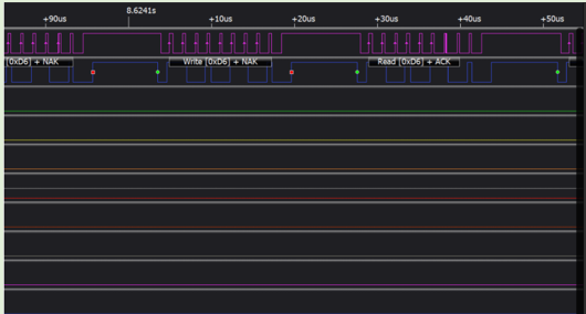
Function Debugging
To debug the I2C function, use the development board (HCM111Z TE-B) with the module and follow these steps:
- Recompile the firmware version and flash it to the module.
- Reboot the module.
- Capture the I2C waveforms with a logic analyzer as shown below:
I2C Master and Slave Mode Debugging
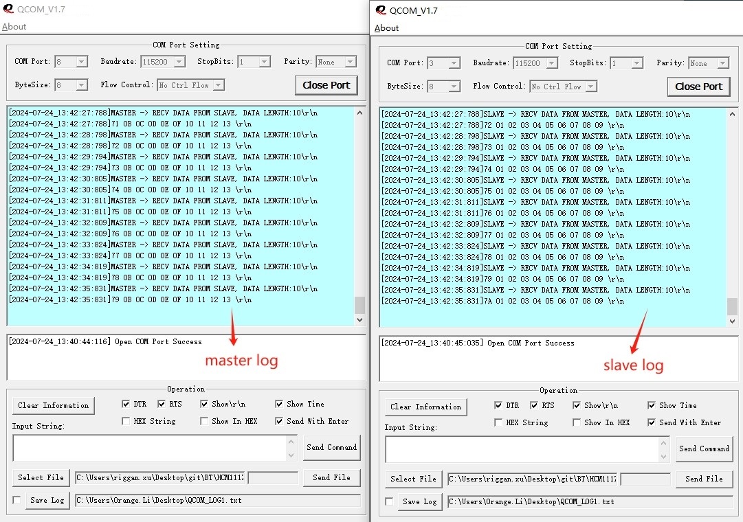
The SDK code of the module provides examples of operating the I2C master and slave modes, which are located in the files ql_i2c_master.c and ql_i2c_slave.c in the directory quectel_demo/ql_i2c_demo/code. In this example, one module communicates via I2C as the master and the other as the slave. The following explains the related functions:
I2C Slave Operation
ql_i2c_demo_slave_init()*`: Initializes I2C slave channel 1, with PA6 serving as SCL, PA7 as SDA, and PA0 indicating that data is ready.
The I2C slave initialization example is as follows:
void ql_i2c_demo_slave_init(void)
{
    ql_debug("I2C SLAVE DEMO RUNNING\\r\\n");

    /* Configure I/O port to check whether data is ready on the slave */
    ql_gpio_set_port_mux(QL_GPIO_PA0, QL_PORTA0_FUNC_A0);
    ql_gpio_set_dir(QL_GPIO_PA0, QL_GMODE_OUTPUT);
    ql_gpio_set_level(QL_GPIO_PA0 , QL_GPIO_OUTPUT_HIGH);

    /* Prepare the data to be sent */
    for(uint32_t i = 0; i < sizeof(slave_send_data); i++)
    {
        slave_send_data[i] = i + 10;
    }

    /* Initialization I2C slave */
    if(QL_I2C_SUCCRSS != ql_i2c_slave_init(QL_I2C_CHANNEL_1, QL_FAST_PLUS_MODE, QL_PIN_MUX_1, IIC_SLVAE_ADDRESS))
    {
        ql_debug("I2C SLAVE INIT FAIL!\\r\\n");
    }

    while(1)
    {
        ql_i2c_slave_receive(QL_I2C_CHANNEL_1, ql_slave_recv_data, &ql_slave_recv_len);
        if(ql_slave_recv_len > 0)
        {
            ql_debug("SLAVE -> RECV DATA FROM MASTER, DATA LENGTH:%d\\r\\n", ql_slave_recv_len);
            for (uint32_t i = 0; i < ql_slave_recv_len; i++)
            {
                ql_debug("%02X ", ql_slave_recv_data[i]);
            }
            ql_debug("\\r\\n");

            ql_gpio_set_level(QL_GPIO_PA0 , QL_GPIO_OUTPUT_HIGH);

            slave_send_data[0] = ql_slave_send_cnt++;
            if(ql_slave_send_cnt > 255) ql_slave_send_cnt = 0;

            ql_i2c_slave_transmit(QL_I2C_CHANNEL_1, slave_send_data, sizeof(slave_send_data));

            /* Notification master */
            ql_gpio_set_level(QL_GPIO_PA0 , QL_GPIO_OUTPUT_LOW);
        }
    }
}
I2C Master Operation
ql_i2c_demo_master_init(): Initializes I2C master channel 1, with PA6 serving as SCL, PA7 as SDA, and PA0 indicating that data is ready.
The I2C master initialization example is as follows:
void ql_i2c_demo_master_init(void)
{
    ql_debug("I2C MASTER DEMO RUNNING\\r\\n");

    /* Configure I/O port to check whether data is ready on the slave */
    ql_gpio_set_port_pull(QL_GPIO_PA0,1);
    ql_gpio_set_port_mux(QL_GPIO_PA0, QL_PORTA0_FUNC_A0);
    ql_gpio_set_dir(QL_GPIO_PA0, QL_GMODE_INPUT_PULLUP);

    /* Prepare the data to be sent */
    for (uint32_t i = 1; i < sizeof(master_send_data); i++)
    {
        master_send_data[i] = i;
    }

    /* Initialization I2C master */
    if(QL_I2C_SUCCRSS != ql_i2c_master_init(QL_I2C_CHANNEL_1, QL_FAST_MODE, QL_PIN_MUX_1))
    {
        ql_debug("I2C MASTER INIT FAIL!\\r\\n");
    }

    while (1)
    {
        /* Master send data counter */
        master_send_data[0] = ql_master_send_cnt++;
        if(ql_master_send_cnt > 255) ql_master_send_cnt = 0;

        /* Master transmit data to slave via i2c port */
        ql_i2c_master_transmit(QL_I2C_CHANNEL_1, IIC_SLVAE_ADDRESS, master_send_data, sizeof(master_send_data));

        /* Master wait for the slave to prepare data */
        while(gpio_get_pin_value(GPIO_PORT_A, GPIO_BIT_0));

        /* Master receive data from slave via i2c port */
        ql_i2c_master_receive(QL_I2C_CHANNEL_1, IIC_SLVAE_ADDRESS, ql_master_recv_data, &ql_master_recv_len);

        ql_debug("MASTER -> RECV DATA FROM SLAVE, DATA LENGTH:%d\\r\\n", ql_master_recv_len);
        for (uint32_t i = 0; i < ql_master_recv_len; i++)
        {
            ql_debug("%02X ", ql_master_recv_data[i]);
        }
        ql_debug("\\r\\n");

        ql_sys_delay_100us(10000);
    }
}
Connect the PA6, PA7, and PA0 pins of the two modules to each other, with PA0 serving as the pin indicating the slave data is ready. The I2C slave will print out the data received from the master and transmit the data back to the master.
Terms and Abbreviations
| Abbreviation | Description |
|---|---|
| ADC | Analog-to-Digital Converter |
| API | Application Programming Interface |
| CLK | Clock |
| CPHA | Clock Phase |
| CPOL | Clock Polarity |
| CS | Chip Select |
| EVB | Evaluation Board |
| GPIO | General-Purpose Input/Output |
| I2C | Inter-Integrated Circuit |
| IoT | Internet of Things |
| PMU | Power Management Unit |
| PWM | Pulse Width Modulation |
| RTOS | Real-Time Operating System |
| SCL | Serial Clock Line |
| SDA | Serial Data Line |
| SDK | Software Development Kit |
| SPI | Serial Peripheral Interface |
| UART | Universal Asynchronous Receiver/Transmitter |
HCM111Z QuecOpen(SDK) Peripheral Interface Development Guide
Introduction
Quectel HCM111Z module supports QuecOpen® solution. QuecOpen® is an embedded development platform, which is intended to simplify the design and development of IoT applications.
This document is applicable to the QuecOpen® solution based on SDK build environment. It outlines how to use GPIO, PMU GPIO, UART, ADC, PWM, SPI and I2C APIs supported by the module to develop corresponding peripheral interfaces in QuecOpen® solution.
GPIO API
Header File
ql_gpio.h, the header file of GPIO API, is in the components/quectel_api/ql_include directory. Unless otherwise specified, all header files mentioned in this document are in this directory.
API Overview
| Function | Description |
|---|---|
ql_gpio_set_port_mux() |
Sets the GPIO multiplexing feature. |
ql_gpio_init() |
Initializes a GPIO pin. |
ql_gpio_set_level() |
Sets the level of the specified GPIO pin. |
ql_gpio_get_level() |
Gets the level of the specified GPIO pin. |
ql_gpio_int_init() |
Initializes and enables the GPIO interrupt. |
ql_gpio_int_disable() |
Disables the configured GPIO interrupt. |
ql_gpio_set_port_pull() |
Sets the pull-up mode when GPIO is used as an input port. |
API Description
ql_gpio_set_port_mux
This function sets the GPIO multiplexing feature.
Prototype:
ql_gpio_errcode_e ql_gpio_set_port_mux(ql_gpio_num_e pin, uint8_t func)
Parameters:
pin: [In] GPIO pin number. See ql_gpio_num_e.func: [In] GPIO multiplexing feature.
Return Value:
Function execution result code. See ql_gpio_errcode_e.
ql_gpio_init
This function initializes a GPIO pin.
Prototype:
ql_gpio_errcode_e ql_gpio_init(ql_gpio_num_e pin, ql_gpio_mode_e mode)
Parameters:
pin: [In] GPIO pin number. See ql_gpio_num_e.mode: [In] GPIO pin mode. See ql_gpio_mode_e.
Return Value:
Function execution result code. See ql_gpio_errcode_e.
ql_gpio_num_e
The enumeration of GPIO pin number:
typedef enum {
  QL_GPIO_PA0,
  QL_GPIO_PA1,
  QL_GPIO_PA2,
  QL_GPIO_PA3,
  QL_GPIO_PA4,
  QL_GPIO_PA5,
  QL_GPIO_PA6,
  QL_GPIO_PA7,
  QL_GPIO_PB0,
  QL_GPIO_PB1,
  QL_GPIO_PB2,
  QL_GPIO_PB3,
  QL_GPIO_PB4,
  QL_GPIO_PB5,
  QL_GPIO_PB6,
  QL_GPIO_PB7,
  QL_GPIO_PC0,
  QL_GPIO_PC1,
  QL_GPIO_PC2,
  QL_GPIO_PC3,
  QL_GPIO_PC4,
  QL_GPIO_PC5,
  QL_GPIO_PC6,
  QL_GPIO_PC7,
  QL_GPIO_PD0,
  QL_GPIO_PD1,
  QL_GPIO_PD2,
  QL_GPIO_PD3,
  QL_GPIO_PD4,
  QL_GPIO_PD5,
  QL_GPIO_PD6,
  QL_GPIO_PD7,
} ql_gpio_num_e
Member:
| Member | Description |
|---|---|
QL_GPIO_PA0 |
GPIOA0 |
QL_GPIO_PA1 |
GPIOA1 |
QL_GPIO_PA2 |
GPIOA2 |
QL_GPIO_PA3 |
GPIOA3 |
QL_GPIO_PA4 |
GPIOA4 |
QL_GPIO_PA5 |
GPIOA5 |
QL_GPIO_PA6 |
GPIOA6 |
QL_GPIO_PA7 |
GPIOA7 |
QL_GPIO_PB0 |
GPIOB0 |
QL_GPIO_PB1 |
GPIOB1 |
QL_GPIO_PB2 |
GPIOB2 |
QL_GPIO_PB3 |
GPIOB3 |
QL_GPIO_PB4 |
GPIOB4 |
QL_GPIO_PB5 |
GPIOB5 |
QL_GPIO_PB6 |
GPIOB6 |
QL_GPIO_PB7 |
GPIOB7 |
QL_GPIO_PC0 |
GPIOC0 |
QL_GPIO_PC1 |
GPIOC1 |
QL_GPIO_PC2 |
GPIOC2 |
QL_GPIO_PC3 |
GPIOC3 |
QL_GPIO_PC4 |
GPIOC4 |
QL_GPIO_PC5 |
GPIOC5 |
QL_GPIO_PC6 |
GPIOC6 |
QL_GPIO_PC7 |
GPIOC7 |
QL_GPIO_PD0 |
GPIOD0 |
QL_GPIO_PD1 |
GPIOD1 |
QL_GPIO_PD2 |
GPIOD2 |
QL_GPIO_PD3 |
GPIOD3 |
QL_GPIO_PD4 |
GPIOD4 |
QL_GPIO_PD5 |
GPIOD5 |
QL_GPIO_PD6 |
GPIOD6 |
QL_GPIO_PD7 |
GPIOD7 |
ql_gpio_mode_e
The enumeration of GPIO pin modes:
typedef enum {
  QL_GMODE_INPUT_PULLDOWN = 1,
  QL_GMODE_INPUT_PULLUP,
  QL_GMODE_OUTPUT = 0,
} ql_gpio_mode_e
Member:
| Member | Description |
|---|---|
QL_GMODE_INPUT_PULLDOWN |
Input is configured for pull-down |
QL_GMODE_INPUT_PULLUP |
Input is configured for pull-up |
QL_GMODE_OUTPUT |
Push-pull output |
ql_gpio_errcode_e
The enumeration of GPIO result codes:
typedef enum {
  QL_GPIO_SUCCESS = 0,
  QL_GPIO_EXECUTE_ERR,
  QL_GPIO_INVALID_PARAM_ERR,
  QL_GPIO_EXTI_LINE_CLASH_ERR,
} ql_gpio_errcode_e
Member:
| Member | Description |
|---|---|
QL_GPIO_SUCCESS |
Successful execution |
QL_GPIO_EXECUTE_ERR |
Failed execution |
QL_GPIO_INVALID_PARAM_ERR |
Invalid parameter |
QL_GPIO_EXTI_LINE_CLASH_ERR |
GPIO interrupt line configuration conflict |
ql_gpio_set_level
This function sets the level of the specified GPIO pin. It is valid only for output pins.
Prototype:
ql_gpio_errcode_e ql_gpio_set_level(ql_gpio_num_e pin, ql_gpio_output_level_e output_level)
Parameters:
pin: [In] GPIO pin number. See ql_gpio_num_e.output_level: [In] Level dedicated for output pins. See ql_gpio_output_level_e.
Return Value:
Function execution result code. See ql_gpio_errcode_e.
ql_gpio_output_level_e
The enumeration of the GPIO output levels:
typedef enum {
  QL_GPIO_OUTPUT_LOW,
  QL_GPIO_OUTPUT_HIGH,
} ql_gpio_output_level_e
Member:
| Member | Description |
|---|---|
QL_GPIO_OUTPUT_LOW |
Low level |
QL_GPIO_OUTPUT_HIGH |
High level |
ql_gpio_get_level
This function gets the level of the specified GPIO pin.
Prototype:
ql_gpio_errcode_e ql_gpio_get_level(ql_gpio_num_e pin, uint32_t *input_level)
Parameters:
pin: [In] GPIO pin number. See ql_gpio_num_e.input_level: [Out] GPIO pin level.
Return Value:
Function execution result code. See ql_gpio_errcode_e.
ql_gpio_int_init
This function initializes and enables the GPIO interrupt.
Prototype:
ql_gpio_errcode_e ql_gpio_int_init(ql_gpio_num_e pin, ql_gpio_irq_trigger_e trigger, ql_gpio_irq_callback callback)
Parameters:
pin: [In] GPIO pin number. See ql_gpio_num_e.trigger: [In] GPIO interrupt triggering mode. See ql_gpio_irq_trigger_e.callback: [In] GPIO interrupt callback function. See ql_gpio_irq_callback.
Return Value:
Function execution result code. See ql_gpio_errcode_e.
ql_gpio_irq_trigger_e
The enumeration of GPIO interrupt triggering modes:
typedef enum {
  QL_IRQ_TRIGGER_LOW_LEVEL,
  QL_IRQ_TRIGGER_HIGH_LEVEL,
  QL_IRQ_TRIGGER_RISING_EDGE,
  QL_IRQ_TRIGGER_FALLING_EDGE,
} ql_gpio_irq_trigger_e
Member:
| Member | Description |
|---|---|
QL_IRQ_TRIGGER_LOW_LEVEL |
GPIO interrupt triggered at low level |
QL_IRQ_TRIGGER_HIGH_LEVEL |
GPIO interrupt triggered at high level |
QL_IRQ_TRIGGER_RISING_EDGE |
GPIO interrupt triggered at rising edge |
QL_IRQ_TRIGGER_FALLING_EDGE |
GPIO interrupt triggered at falling edge |
ql_gpio_irq_callback
This is the callback function of GPIO interrupt.
Prototype:
typedef void (*ql_gpio_irq_callback)(void *arg, uint8_t line)
Parameters:
arg: [In] Pin for triggering the GPIO interrupt.line: [Out] Serial number of the external interrupt line that triggers the GPIO interrupt.
ql_gpio_int_disable
This function disables the configured GPIO interrupt.
Prototype:
ql_gpio_errcode_e ql_gpio_int_disable(ql_gpio_num_e pin)
Parameters:
pin: [In] GPIO pin number. See ql_gpio_num_e.
Return Value:
Function execution result code. See ql_gpio_errcode_e.
ql_gpio_set_port_pull
This function sets the pull-up mode when GPIO is used as an input port.
Prototype:
ql_gpio_errcode_e ql_gpio_set_port_pull(ql_gpio_num_e pin, uint8_t enable)
Parameters:
pin: [In] GPIO pin number. See ql_gpio_num_e.enable: [In] Set the pull-up mode.
True Enable the pull-up mode
False No setting
Return Value:
Function execution result code. See ql_gpio_errcode_e.
GPIO Development Process
This chapter describes how to use the above GPIO API to configure GPIO pins and perform basic debugging. QL_GPIO_PD4, QL_GPIO_PD5 and QL_GPIO_PD6 are used in the following examples by default.
GPIO Operation
The example of how to use the GPIO API is provided in the quectel_demo/ql_gpio_demo/code/ql_gpio_demo.c file in the module SDK. The related functions are described as follows:
demo_gpio(): Initializes a GPIO pin and enables the GPIO interruptql_gpio_irq_test(): This is the interrupt callback function. It can implement functionalities such as setting the GPIO pin level and disabling GPIO interrupts.
The example of using the GPIO API is as follows:
void demo_gpio(void)
{
    ql_debug("digital gpio demo\\r\\n");
    //digital gpio output
    ql_gpio_set_port_mux(QL_GPIO_PD4 , QL_PORTD4_FUNC_D4);
    ql_gpio_set_port_mux(QL_GPIO_PD5 , QL_PORTD5_FUNC_D5);
    ql_gpio_set_port_mux(QL_GPIO_PD6 , QL_PORTD6_FUNC_D6);
    ql_gpio_init(QL_GPIO_PD4,QL_GMODE_OUTPUT);
    ql_gpio_init(QL_GPIO_PD5,QL_GMODE_INPUT_PULLDOWN);
    ql_gpio_set_level(QL_GPIO_PD4,QL_GPIO_OUTPUT_HIGH);
    ql_gpio_init(QL_GPIO_PD6 , QL_GMODE_INPUT_PULLDOWN);
    ql_gpio_int_init(QL_GPIO_PD6, QL_IRQ_TRIGGER_RISING_EDGE , ql_gpio_irq_test);
}
void ql_gpio_irq_test (void *arg,uint8_t line)
{
    static int cnt = 0;
    uint32_t input_level = 0;
    ql_gpio_get_level(QL_GPIO_PD5,&input_level);
    ql_debug("exit_line=%d\\r\\n",line);
    ql_debug(" gpio5 read=%d\\r\\n",input_level);
    if(input_level == 0){
        ql_gpio_set_level(QL_GPIO_PD4,QL_GPIO_OUTPUT_LOW);
    }else{
        ql_gpio_set_level(QL_GPIO_PD4,QL_GPIO_OUTPUT_HIGH);
    }
    cnt++;
    ql_debug(" int cnt=%d\\r\\n",cnt);
    if(cnt >= 10){
        ql_gpio_int_disable(QL_GPIO_PD6);
        cnt = 0;
    }
}
Function Debugging
To debug the GPIO function, use the development board (HCM111Z TE-B) with the module and follow these steps:
- Recompile the firmware version and flash it to the module.
- Reboot the module.
- Open UART port 1 to obtain the debugging logs. The log information will be displayed as follows:

If the following information is printed during the debugging, it indicates that the GPIO interrupt has been triggered.

PMU GPIO API
Header File
ql_pmu_gpio.h, the header file of PMU GPIO API, is in the components/quectel_api/ql_include directory. Unless otherwise specified, all header files mentioned in this document are in this directory.
The functional difference between GPIO and PMU GPIO pins is that the PMU GPIO pins can keep the output level unchanged when the module is in sleep state.
API Overview
| Function | Description |
|---|---|
ql_pmu_gpio_init() |
Initializes a PMU GPIO pin. |
ql_pmu_gpio_set_level() |
Sets the level of the specified PMU GPIO pin. |
ql_pmu_gpio_get_level() |
Gets the level of the specified PMU GPIO pin. |
ql_pmu_gpio_int_init() |
Initializes and enables the PMU GPIO interrupt. |
ql_pmu_gpio_int_disable() |
Disables the configured PMU GPIO interrupt. |
API Description
ql_pmu_gpio_init
This function initializes a PMU GPIO pin.
Prototype:
ql_gpio_errcode_e ql_pmu_gpio_init(ql_gpio_num_e pin, ql_gpio_mode_e mode)
Parameters:
pin: [In] PMU GPIO pin number. See ql_gpio_num_e.mode: [In] PMU GPIO mode. See ql_gpio_mode_e.
Return Value:
Function execution result code. See ql_gpio_errcode_e.
ql_pmu_gpio_set_level
This function sets the level of the specified PMU GPIO pin. It is valid only for output pins.
Prototype:
ql_gpio_errcode_e ql_pmu_gpio_set_level(ql_gpio_num_e pin, ql_gpio_output_level_e output_level)
Parameters:
pin: [In] PMU GPIO pin number. See ql_gpio_num_e.output_level: [In] Level dedicated for output pins. See ql_gpio_output_level_e.
Return Value:
Function execution result code. See ql_gpio_errcode_e.
ql_pmu_gpio_get_level
This function gets the level of the specified PMU GPIO pin.
Prototype:
ql_gpio_errcode_e ql_pmu_gpio_get_level(ql_gpio_num_e pin, uint32_t *input_level)
Parameters:
pin: [In] PMU GPIO pin number. See ql_gpio_num_e.input_level: [Out] PMU GPIO pin level.
Return Value:
Function execution result code. See ql_gpio_errcode_e.
ql_pmu_gpio_int_init
This function initializes and enables the PMU GPIO interrupt.
Prototype:
ql_gpio_errcode_e ql_pmu_gpio_int_init(ql_gpio_num_e pin, ql_gpio_irq_trigger_e trigger, ql_pmu_gpio_irq_callback callback)
Parameters:
pin: [In] PMU GPIO pin number. See ql_gpio_num_e.trigger: [In] PMU GPIO interrupt triggering mode. See ql_gpio_irq_trigger_e.callback: [In] PMU GPIO interrupt callback function. See ql_pmu_gpio_irq_callback.
Return Value:
Function execution result code. See ql_gpio_errcode_e.
ql_pmu_gpio_irq_callback
This is the callback function of PMU GPIO interrupt.
Prototype:
typedef void (*ql_pmu_gpio_irq_callback)(void *arg)
Parameters:
arg: [Out] Reserved.
ql_pmu_gpio_int_disable
This function disables the configured PMU GPIO interrupt.
Prototype:
ql_gpio_errcode_e ql_pmu_gpio_int_disable(ql_gpio_num_e pin)
Parameters:
pin: [In] PMU GPIO pin number. See ql_gpio_num_e.
Return Value:
Function execution result code. See ql_gpio_errcode_e.
PMU GPIO Development Process
This chapter describes how to use the above PMU GPIO API to configure PMU GPIO pins and perform basic debugging. QL_GPIO_PD4, QL_GPIO_PD5 and QL_GPIO_PD6 are used in the following examples by default.
PMU GPIO Operation
The example of how to use the PMU GPIO API is provided in the quectel_demo/ql_pmu_gpio_demo/code/ql_pmu_gpio_demo.c file in the module SDK. The related functions are described as follows:
demo_pmu_gpio(): Initializes PMU GPIO and enables the PMU GPIO interruptql_gpio_pmu_irq_test(): This is the interrupt callback function. It can implement the functionalities such as getting the pin level of PMU GPIO, setting the level of PMU GPIO pin and disabling the PMU GPIO interrupt.
The example of using the PMU GPIO API is as follows:
void demo_pmu_gpio(void)
{
    ql_debug("pmu gpio demo\\r\\n");
    ql_pmu_gpio_init(QL_GPIO_PD4,QL_GMODE_OUTPUT);
    ql_pmu_gpio_init(QL_GPIO_PD5,QL_GMODE_INPUT_PULLDOWN);
    ql_pmu_gpio_set_level(QL_GPIO_PD4,QL_GPIO_OUTPUT_HIGH);
    ql_pmu_gpio_int_init(QL_GPIO_PD6, QL_IRQ_TRIGGER_FALLING_EDGE, ql_gpio_pmu_irq_test);//wakeup pin
}

void ql_gpio_pmu_irq_test (void *arg)
{
    static int cnt = 0;
    uint32_t input_level = 0;
    ql_pmu_gpio_get_level(QL_GPIO_PD5,&input_level);
    ql_debug(" gpio5 read=%d\\r\\n",input_level);
    if(input_level == 0){
        ql_pmu_gpio_set_level(QL_GPIO_PD4,QL_GPIO_OUTPUT_LOW);
    }else{
        ql_pmu_gpio_set_level(QL_GPIO_PD4,QL_GPIO_OUTPUT_HIGH);
    }
    cnt++;
    ql_debug(" int cnt=%d\\r\\n",cnt);
    if(cnt >= 10){
        ql_pmu_gpio_int_disable(QL_GPIO_PD6);
        cnt = 0;
    }
}
Function Debugging
To debug the PMU GPIO function, use the development board (HCM111Z TE-B) with the module and follow these steps:
- Recompile the firmware version and flash it to the module.
- Reboot the module.
- Open UART port 1 to obtain the debugging logs. The log information will be displayed as follows:

If the following information is printed during the debugging, it indicates that the PMU GPIO interrupt has been triggered.

UART API
Header File
ql_uart.h, the header file of UART API, is in the components/quectel_api/ql_include directory. Unless otherwise specified, all header files mentioned in this document are in this directory.
API Overview
| Function | Description |
|---|---|
ql_uart_set_dcbconfig() |
Sets the UART port properties. |
ql_uart_get_dcbconfig() |
Gets the configuration of UART port properties. |
ql_uart_open() |
Opens the UART port. |
ql_uart_close() |
Closes the UART port. |
ql_uart_write() |
Writes data to the module through the UART port. |
ql_uart_read() |
Reads the data from the module through the UART port. |
ql_uart_set_rx_cb() |
Registers the callback function for UART data interrupt. |
API Description
ql_uart_set_dcbconfig
This function sets the UART port properties, which take effect after the UART port is re-opened.
Prototype:
ql_uart_errcode_e ql_uart_set_dcbconfig(ql_uart_port_number_e port, ql_uart_config_s *dcb)
Parameters:
port: [In] UART port number. See ql_uart_port_number_e.dcb: [In] Configuration of UART port properties. See ql_uart_config_s.
Return Value:
Function execution result code. See ql_uart_errcode_e.
ql_uart_port_number_e
The enumeration of the UART port number is defined below. The module currently supports two UART ports.
typedef enum {
  QL_UART_PORT_1,
  QL_UART_PORT_2,
} ql_uart_port_number_e
Member:
| Member | Description |
|---|---|
QL_UART_PORT_1 |
UART port 1 |
QL_UART_PORT_2 |
UART port 2 |
ql_uart_config_s
The structure of the configuration of UART port properties:
typedef struct {
  uint8_t is_debug_port;
  ql_uart_baud_e baudrate;
  ql_uart_databit_e data_bit;
  ql_uart_stopbit_e stop_bit;
  ql_uart_parityit_e parity_bit;
} ql_uart_config_s
Parameter:
| Type | Parameter | Description |
|---|---|---|
| uint8_t | is_debug_port |
Print log (0: Receive and send data) |
| ql_uart_baud_e | baudrate |
Baud rate. Default: 115200 bps.See ql_uart_baud_e |
| ql_uart_databit_e | data_bit |
Data bit. Default: 8 bits.See ql_uart_databit_e |
| ql_uart_stopbit_e | stop_bit |
Stop bit. Default: 1 bit.See ql_uart_stopbit_e |
| ql_uart_parityit_e | parity_bit |
Parity bit. Default: No parity bit.See ql_uart_parityit_e |
ql_uart_baud_e
The enumeration of baud rates:
typedef enum {
  QL_UART_BAUD_2400 = 2400,
  QL_UART_BAUD_4800 = 4800,
  QL_UART_BAUD_9600 = 9600,
  QL_UART_BAUD_14400 = 14400,
  QL_UART_BAUD_19200 = 19200,
  QL_UART_BAUD_38400 = 38400,
  QL_UART_BAUD_57600 = 57600,
  QL_UART_BAUD_115200 = 115200,
  QL_UART_BAUD_230400 = 230400,
  QL_UART_BAUD_460800 = 460800,
  QL_UART_BAUD_921600 = 921600,
} ql_uart_baud_e
Member:
| Member | Description |
|---|---|
QL_UART_BAUD_2400 |
2400 bps |
QL_UART_BAUD_4800 |
4800 bps |
QL_UART_BAUD_9600 |
9600 bps |
QL_UART_BAUD_14400 |
14400 bps |
QL_UART_BAUD_19200 |
19200 bps |
QL_UART_BAUD_38400 |
38400 bps |
QL_UART_BAUD_57600 |
57600 bps |
QL_UART_BAUD_115200 |
115200 bps |
QL_UART_BAUD_230400 |
230400 bps |
QL_UART_BAUD_460800 |
460800 bps |
QL_UART_BAUD_921600 |
921600 bps |
ql_uart_databit_e
The enumeration of data bits:
typedef enum {
  QL_UART_DATABIT_5,
  QL_UART_DATABIT_6,
  QL_UART_DATABIT_7,
  QL_UART_DATABIT_8,
} ql_uart_databit_e
Member:
| Member | Description |
|---|---|
QL_UART_DATABIT_5 |
5 bits |
QL_UART_DATABIT_6 |
6 bits |
QL_UART_DATABIT_7 |
7 bits |
QL_UART_DATABIT_8 |
8 bits |
ql_uart_stopbit_e
The enumeration of stop bits:
typedef enum {
  QL_UART_STOP_1,
  QL_UART_STOP_2,
} ql_uart_stopbit_e
Member:
| Member | Description |
|---|---|
QL_UART_STOP_1 |
1 bit |
QL_UART_STOP_2 |
2 bits |
ql_uart_parityit_e
The enumeration of parity bits:
typedef enum {
  QL_UART_PARITY_NONE,
  QL_UART_PARITY_ODD,
  QL_UART_PARITY_EVEN,
} ql_uart_parityit_e
Member:
| Member | Description |
|---|---|
QL_UART_PARITY_NONE |
No parity |
QL_UART_PARITY_ODD |
Odd parity |
QL_UART_PARITY_EVEN |
Even parity |
ql_uart_errcode_e
The enumeration of UART result codes:
typedef enum {
  QL_UART_SUCCESS = 0,
  QL_UART_EXECUTE_ERR,
  QL_UART_MEM_ADDR_NULL_ERR,
  QL_UART_INVALID_PARAM_ERR,
  QL_UART_NOT_OPEN_ERR,
} ql_uart_errcode_e
Member:
| Member | Description |
|---|---|
QL_UART_SUCCESS |
Successful execution |
QL_UART_EXECUTE_ERR |
Failed execution |
QL_UART_MEM_ADDR_NULL_ERR |
Parameter address is null |
QL_UART_INVALID_PARAM_ERR |
Invalid parameter |
QL_UART_NOT_OPEN_ERR |
UART port is not open |
ql_uart_get_dcbconfig
This function gets the configuration of UART port properties.
Prototype:
ql_uart_errcode_e ql_uart_get_dcbconfig(ql_uart_port_number_e port, ql_uart_config_s *dcb)
Parameters:
port: [In] UART port number. See ql_uart_port_number_e.dcb: [In] Configuration of UART port properties. See ql_uart_config_s.
Return Value:
Function execution result code. See ql_uart_errcode_e.
ql_uart_open
This function opens the UART port.
Prototype:
ql_uart_errcode_e ql_uart_open(ql_uart_port_number_e port)
Parameters:
port: [In] UART port number. See ql_uart_port_number_e.
Return Value:
Function execution result code. See ql_uart_errcode_e.
ql_uart_close
This function closes the UART port.
Prototype:
ql_uart_errcode_e ql_uart_close(ql_uart_port_number_e port)
Parameters:
port: [In] UART port number. See ql_uart_port_number_e.
Return Value:
Function execution result code. See ql_uart_errcode_e.
ql_uart_write
This function writes data to the module through the UART port.
Prototype:
int ql_uart_write(ql_uart_port_number_e port, unsigned char *data, unsigned int data_len)
Parameters:
port: [In] UART port number. See ql_uart_port_number_e.data: [In] Written data.data_len: [In] Length of written data.
Return Value:
Function execution result code. See ql_uart_errcode_e.
ql_uart_read
This function reads the data from the module through the UART port.
Prototype:
int ql_uart_read(ql_uart_port_number_e port, unsigned char *data, unsigned int data_len)
Parameters:
port: [In] UART port number. See ql_uart_port_number_e.data: [Out] Read data.data_len: [In] Length of read data.
Return Value:
Function execution result code. See ql_uart_errcode_e.
ql_uart_set_rx_cb
This function registers the callback function that is triggered when a data interrupt is received via the UART port.
Prototype:
ql_uart_errcode_e ql_uart_set_rx_cb(ql_uart_port_number_e port, ql_uart_callback uart_cb)
Parameters:
port: [In] UART port number. See ql_uart_port_number_e.uart_cb: [In] Callback function to be registered. See ql_uart_callback.
Return Value:
Function execution result code. See ql_uart_errcode_e.
ql_uart_callback
This is the callback function that handles the UART interrupt.
Prototype:
typedef void (*ql_uart_callback)(char value)
Parameters:
value: [In] Data received via the UART port.
Return Value:
None
UART Development Process
This chapter describes how to use the above UART API in the application and perform basic debugging. UART 0 is used in the following example by default.
UART Operation
The example of how to use the UART API is provided in the quectel_demo/ql_uart_demo/code/ql_uart_demo.c file in the module SDK. The related functions are described as follows:
demo_uart(): Initializes the UART port and registers the interrupt callback function.ql_uart_cb_test(): Interrupt callback function that handles the data received through the UART port.
The example of using the UART API is as follows:
void demo_uart(void)
{
    ql_uart_config_s cfg = {
        .is_debug_port = 0, //0 | 1
        .baudrate = QL_UART_BAUD_115200,
        .data_bit = QL_UART_DATABIT_8,
        .stop_bit = QL_UART_STOP_1,
        .parity_bit = QL_UART_PARITY_NONE,
    };
    ql_debug("uart demo\\r\\n");
    ql_gpio_set_port_mux(QL_GPIO_PD4,QL_PORTD4_FUNC_UART0_RXD);
    ql_gpio_set_port_mux(QL_GPIO_PD5,QL_PORTD5_FUNC_UART0_TXD);
    ql_gpio_set_port_pull(QL_GPIO_PD4, true);
    ql_uart_set_dcbconfig(QL_UART_PORT_0,&cfg);
    ql_uart_set_rx_cb(QL_UART_PORT_0,ql_uart_cb_test);
    ql_uart_open(QL_UART_PORT_0);
}

void ql_uart_cb_test(char value)
{
    char data = value;
    ql_debug("recv %0x\\r\\n",data);
    ql_uart_write(QL_UART_PORT_0,(unsigned char*)&data,1);
}
Function Debugging
To debug the UART function, use the development board (HCM111Z TE-B) with the module and follow these steps:
- Recompile the firmware version and flash it to the module.
- Reboot the module.
- Open UART port 1 to obtain the debugging logs. The log information will be displayed as follows:

ADC API
Header File
ql_adc.h, the header file of ADC API, is in the components/quectel_api/ql_include directory. Unless otherwise specified, all header files mentioned in this document are in this directory.
API Overview
| Function | Description |
|---|---|
ql_adc_channel_init() |
Configures ADC channel parameters. |
ql_adc_channel_start() |
Enables ADC channel detection. |
ql_adc_channel_stop() |
Disables ADC channel detection. |
API Description
ql_adc_channel_init
This function configures ADC channel parameters.
Prototype:
ql_adc_errcode_e ql_adc_channel_init(ql_adc_obj_s *handle, ql_adc_obj_callback cb, ql_adc_channel_e channel, void *user_data)
Parameters:
handle: [In] ADC channel. See ql_adc_obj_s.cb: [In] Callback function for ADC channel detection. See ql_adc_obj_callback.channel: [In] ADC channel number. See ql_adc_channel_e.user_data: [In] User data.
Return Value:
Function execution result code. See ql_adc_errcode_e.
ql_adc_obj_s
The structure of ADC channels:
typedef struct adc_obj_ {
  void *user_data;
  ql_adc_channel_e channel;
  ql_adc_obj_callback cb;
  struct adc_obj_ *next;
} ql_adc_obj_s
Parameter:
| Type | Parameter | Description |
|---|---|---|
| void | user_data |
User data. |
| ql_adc_channel_e | channel |
ADC channel number. |
| ql_adc_obj_callback | cb |
Callback function for channel detection. |
| struct adc_obj_ | next |
Address of the next node in the Linked List. |
ql_adc_obj_callback
This function is the callback function for ADC channel detection.
Prototype:
typedef void (*ql_adc_obj_callback)(ql_adc_channel_e channel, int value, void *user_data)
Parameters:
channel: [Out] ADC channel number. See ql_adc_channel_e.value: [In] ADC channel voltage sampling result. Range: 0--1023. Reference voltage: 3.3 V. When the sampling result is 1023, it means that the channel voltage is greater than or equal to 3.3 V.user_data: [In] User data.
Return Value:
None
ql_adc_channel_e
The enumeration of ADC channel number.
typedef enum {
  QL_ADC_CHANNEL_0 = 0x01,
  QL_ADC_CHANNEL_1 = 0x02,
  QL_ADC_CHANNEL_2 = 0x04,
  QL_ADC_CHANNEL_3 = 0x08,
} ql_adc_channel_e
Parameter:
| Parameter | Description |
|---|---|
QL_ADC_CHANNEL_0 |
Channel 0, detecting voltage for QL_GPIO_PD4. |
QL_ADC_CHANNEL_1 |
Channel 1, detecting voltage for QL_GPIO_PD5. |
QL_ADC_CHANNEL_2 |
Channel 2, detecting voltage for QL_GPIO_PD6. |
QL_ADC_CHANNEL_3 |
Channel 3, detecting voltage for QL_GPIO_PD7. |
ql_adc_errcode_e
The enumeration of ADC result codes:
typedef enum {
  QL_ADC_SUCCESS = 0,
  QL_ADC_EXECUTE_ERR,
  QL_ADC_INVALID_PARAM_ERR,
} ql_adc_errcode_e
Parameter:
| Parameter | Description |
|---|---|
QL_ADC_SUCCESS |
Successful execution |
QL_ADC_EXECUTE_ERR |
Failed execution |
QL_ADC_INVALID_PARAM_ERR |
Invalid parameter |
ql_adc_channel_start
This function enables ADC channel detection.
Prototype:
ql_adc_errcode_e ql_adc_channel_start(ql_adc_obj_s *handle)
Parameters:
handle: [In] ADC channel. See ql_adc_obj_s.
Return Value:
Function execution result code. See ql_adc_errcode_e.
ql_adc_channel_stop
This function disables ADC channel detection.
Prototype:
ql_adc_errcode_e ql_adc_channel_stop(ql_adc_obj_s *handle)
Parameters:
handle: [In] ADC channel. See ql_adc_obj_s.
Return Value:
Function execution result code. See ql_adc_errcode_e.
ADC Development Process
This chapter describes how to use the above ADC API in the application, and perform basic debugging. In the example, channel 0 is used for test by default.
ADC Operation
The example of how to use the ADC API is provided in the quectel_demo/ql_adc_demo/code/ql_adc_demo.c file the module SDK. The related functions are described as follows:
demo_adc(): Configure and initialize ADC channels.adc_tim_fn(): The timer callback function, which implements ADC channel detection every 1 s.
The example of using ADC API is as follows:
void demo_adc(void)
{
    ql_debug("adc demo\\r\\n");
    ql_gpio_set_port_mux(QL_GPIO_PD4,QL_PORTD4_FUNC_ADC0);
    ql_soft_timer_init(&adc_timer , adc_tim_fn , NULL);
    ql_soft_timer_start(&adc_timer,1000,1);
}
void adc_tim_fn(void *arg)
{
    ql_adc_channel_init(&ql_test_adc , ql_adc_detect_callback , QL_ADC_CHANNEL_0 , NULL);
    ql_adc_channel_start(&ql_test_adc);
    ql_adc_channel_stop(&ql_test_adc);
}
You can print the result of ADC channel detection through ql_adc_detect_callback() as follows:
static void ql_adc_detect_callback(ql_adc_channel_e channel, int value , void *user_data)
{
    ql_debug("adc channel %d , value %d \\r\\n" , channel , value);
}
Function Debugging
To debug the ADC function, use the development board (HCM111Z TE-B) with the module and follow these steps:
- Recompile the firmware version and flash it to the module.
- Reboot the module.
- Open UART port 1 to obtain the debugging logs. Change the input voltage of the pin and the detection value changes accordingly. The log information will be displayed as follows:

PWM API
Header File
ql_pwm.h, the header file of PWM API, is in the components/quectel_api/ql_include directory. Unless otherwise specified, all header files mentioned in this document are in this directory.
API Overview
| Function | Description |
|---|---|
ql_pwm_init() |
Initializes PWM. |
ql_pwm_update_param() |
Updates the PWM parameters. |
ql_pwm_enable() |
Enables PWM output. |
ql_pwm_disable() |
Disables PWM output. |
API Description
ql_pwm_init
This function initializes PWM.
Prototype:
ql_pwm_errcode_e ql_pwm_init(ql_pwm_channel_e channel, uint32_t frequency, uint32_t high_duty)
Parameters:
channel: [In] PWM channel. See ql_pwm_channel_e.frequency: [In] PWM frequency.high_duty: [In] PWM duty cycle.
Return Value:
Function execution result code. See ql_pwm_errcode_e.
ql_pwm_channel_e
The enumeration of PWM channels. There are 6 PWM channels in total.
typedef enum {
  QL_PWM_0 = 0,
  QL_PWM_1,
  QL_PWM_2,
  QL_PWM_3,
  QL_PWM_4,
  QL_PWM_5,
} ql_pwm_channel_e
Member:
| Member | Description |
|---|---|
QL_PWM_0 |
PWM 0 |
QL_PWM_1 |
PWM 1 |
QL_PWM_2 |
PWM 2 |
QL_PWM_3 |
PWM 3 |
QL_PWM_4 |
PWM 4 |
QL_PWM_5 |
PWM 5 |
ql_pwm_errcode_e
The enumeration of PWM result codes:
typedef enum {
  QL_PWM_SUCCESS = 0,
  QL_PWM_EXECUTE_ERR,
  QL_PWM_INVALID_PARAM_ERR,
} ql_pwm_errcode_e
Member:
| Member | Description |
|---|---|
QL_PWM_SUCCESS |
Successful execution |
QL_PWM_EXECUTE_ERR |
Failed execution |
QL_PWM_INVALID_PARAM_ERR |
Invalid parameter |
ql_pwm_update_param
This function updates the PWM parameters. The updated parameters take effect in next PWM period.
Prototype:
ql_pwm_errcode_e ql_pwm_update_param(ql_pwm_channel_e channel, uint32_t frequency, uint32_t high_duty)
Parameters:
channel: [In] PWM channel. See ql_pwm_channel_e.frequency: [In] PWM frequency.high_duty: [In] PWM duty cycle.
Return Value:
Function execution result code. See ql_pwm_errcode_e.
ql_pwm_enable
This function enables PWM output.
Prototype:
ql_pwm_errcode_e ql_pwm_enable(ql_pwm_channel_e channel)
Parameters:
channel: [In] PWM channel. See ql_pwm_channel_e.
Return Value:
Function execution result code. See ql_pwm_errcode_e.
ql_pwm_disable
This function disables PWM output.
Prototype:
ql_pwm_errcode_e ql_pwm_disable(ql_pwm_channel_e channel)
Parameters:
channel: [In] PWM channel. See ql_pwm_channel_e.
Return Value:
Function execution result code. See ql_pwm_errcode_e.
PWM Development Process
This chapter describes how to use the above PWM API in the application, and perform simple debugging. In the example, QL_PWM_4 and QL_PWM_5 are used for test by default.
PWM Operation
The example of how to use the PWM API is provided in the quectel_demo/ql_pwm_demo/code/ql_pwm_demo.c file in the module SDK. The related functions are described as follows:
demo_pwm(): Initializes PWM, enables PWM output and disables PWM output.
The example of using PWM API is as follows:
void demo_pwm(void)
{
    ql_debug("digital_pwm demo\\r\\n");
    ql_gpio_set_port_mux(QL_GPIO_PD4,QL_PORTD4_FUNC_PWM4);
    ql_gpio_set_port_mux(QL_GPIO_PD5,QL_PORTD5_FUNC_PWM5);
    ql_pwm_init(QL_PWM_4,1000,50);
    ql_pwm_init(QL_PWM_5,1000,80);
    ql_pwm_enable(QL_PWM_4);
    ql_pwm_enable(QL_PWM_5);
    ql_sys_delay_100us(20000); //1 kHz for 2 s
    ql_pwm_update_param(QL_PWM_4,10000,80);
    ql_pwm_update_param(QL_PWM_5,10000,50);
    ql_sys_delay_100us(10000); //10K Hz for 1 s
    ql_pwm_disable(QL_PWM_4);
    ql_pwm_disable(QL_PWM_5);
    ql_sys_delay_100us(20000); //Stop for 2 s
    ql_pwm_enable(QL_PWM_4);
    ql_pwm_enable(QL_PWM_5);
    ql_sys_delay_100us(10000); //Restart PWM with 10 kHz for 1 s
    ql_pwm_disable(QL_PWM_4);
    ql_pwm_disable(QL_PWM_5);
}
Function Debugging
To debug the PWM function use the development board (HCM111Z TE-B) with the module and follow these steps:
- Recompile the firmware version and flash it to the module.
- Reboot the module.
- Open UART port 1 to obtain the debugging logs. The log information will be displayed as follows:


SPI API
Header File
ql_spi.h, the header file of SPI API, is in the components/quectel_api/ql_include directory. Unless otherwise specified, all header files mentioned in this document are in this directory.
API Overview
| Function | Description |
|---|---|
ql_spi_init() |
Initializes SPI. |
ql_spi_transfer() |
Sends or receives SPI data. |
API Description
ql_spi_init
This function initializes SPI.
Prototype:
ql_spi_errcode_e ql_spi_init(ql_spi_config_s spi_cfg)
Parameters:
spi_cfg: [In] SPI configuration. See ql_spi_config_s.
Return Value:
Function execution result code. See ql_spi_errcode_e.
ql_spi_config_s
The structure of SPI configuration:
typedef struct {
  uint32_t spiclk;
  ql_spi_cpol_pol_e cpol;
  ql_spi_cpha_pol_e cpha;
  ql_spi_master_slave_mode_e masterorslave;
  void (*spi_cs_ctrl)(uint8_t);
} ql_spi_config_s
Parameter:
| Type | Parameter | Description |
|---|---|---|
| uint32_t | spiclk |
SPI clock frequency. Maximum value: 24 MHz. |
| ql_spi_cpol_pol_e | cpol |
SPI clock polarity.See ql_spi_cpol_pol_e. |
| ql_spi_cpha_pol_e | cpha |
SPI clock phase.See ql_spi_cpha_pol_e. |
| ql_spi_master_slave_mode_e | masterorslave |
SPI master or slave selection.See ql_spi_master_slave_mode_e. |
| void (*spi_cs_ctrl)(uint8_t) | spi_cs_ctrl |
Function pointer for controlling CS pin.See ql_spi_cs_ctrl() in SPI Operation. |
ql_spi_cpol_pol_e
The enumeration of SPI clock polarities:
typedef enum {
  QL_SPI_CPOL_LOW = 0,
  QL_SPI_CPOL_HIGH,
} ql_spi_cpol_pol_e
Member:
| Member | Description |
|---|---|
QL_SPI_CPOL_LOW |
SCK is at a low level during the idle state. |
QL_SPI_CPOL_HIGH |
SCK is at a high level during the idle state. |
ql_spi_cpha_pol_e
The enumeration of SPI clock phases:
typedef enum {
  QL_SPI_CPHA_1Edge,
  QL_SPI_CPHA_2Edge,
} ql_spi_cpha_pol_e
Member:
| Member | Description |
|---|---|
QL_SPI_CPHA_1Edge |
Sample data on the edge of the first period of SCK. |
QL_SPI_CPHA_2Edge |
Sample data on the edge of the second period of SCK. |
ql_spi_master_slave_mode_e
The enumeration of SPI master or slave selections:
typedef enum {
  QL_SPI_MASTER = 0,
  QL_SPI_SLAVE,
} ql_spi_master_slave_mode_e
Member:
| Member | Description |
|---|---|
QL_SPI_MASTER |
SPI serves as the master. |
QL_SPI_SLAVE |
SPI serves as the slave (Currently not supported). |
ql_spi_errcode_e
The enumeration of SPI result codes:
typedef enum {
  QL_SPI_SUCCESS = 0,
  QL_SPI_EXECUTE_ERR,
  QL_SPI_INVALID_PARAM_ERR,
} ql_spi_errcode_e
Member:
| Member | Description |
|---|---|
QL_SPI_SUCCESS |
Successful execution |
QL_SPI_EXECUTE_ERR |
Failed execution |
QL_SPI_INVALID_PARAM_ERR |
Invalid parameter |
ql_spi_transfer
This function sends or receives SPI data.
Prototype:
ql_errcode_spi_e ql_spi_transfer(ql_spi_messag_s *spi_msg)
Parameters:
spi_msg: [In] Data sent or received via SPI. See ql_spi_messag_s.
Return Value:
Function execution result code. See ql_spi_errcode_e.
ql_spi_messag_s
The structure of data sent or received via SPI:
typedef struct {
  UINT8 *send_buf;
  UINT32 send_len;
  UINT8 *recv_buf;
  UINT32 recv_len;
} ql_spi_message_s
Parameter:
| Type | Parameter | Description |
|---|---|---|
| UINT8 | send_buf |
Sent data |
| UINT32 | send_len |
Length of the sent data |
| UINT8 | recv_buf |
Received data |
| UINT32 | recv_len |
Length of the received data |
SPI Development Process
This chapter describes how to use the above SPI API in the application, and perform basic debugging.
SPI Operation
The example of how to use the SPI API is provided in the quectel_demo/ql_spi_demo/code/ql_spi_demo.c file in the module SDK. The related functions are described as follows:
demo_spi_master(): Initializes SPI, sends and receives data.ql_spi_cs_ctrl(): Controls CS pin.
The example of using SPI API is as follows:
void demo_spi_master(void)
{
    ql_debug("spi master demo\\r\\n");
    uint8_t send_buff[128] = {0};
    uint8_t recv_buff[128] = {0};
    int i = 0;
    for(i=0;i<128;i++)
        send_buff[i] = i;
    ql_spi_config_s cfg = {
        .spiclk = 3000000,
        .cpol = QL_SPI_CPOL_LOW,
        .cpha = QL_SPI_CHPA_1EDGE,
        .masterorslave = QL_SPI_MASTER,
        .spi_cs_ctrl = ql_spi_cs_ctrl,
    };
    ql_spi_message_s msg = {
        .send_buf = send_buff,
        .send_len = 128,
        .recv_buf = recv_buff,
        .recv_len = 128,
    };
    ql_gpio_set_port_mux(QL_GPIO_PD4, QL_PORTD4_FUNC_SSP0_CLK);
    //ql_gpio_set_port_mux(QL_GPIO_PD5, QL_PORTD5_FUNC_SSP0_CSN);
    ql_gpio_set_port_mux(QL_GPIO_PD5, QL_PORTD5_FUNC_D5);
    ql_gpio_init(QL_GPIO_PD5,QL_GMODE_OUTPUT);
    ql_gpio_set_port_mux(QL_GPIO_PD6, QL_PORTD6_FUNC_SSP0_DOUT);
    ql_gpio_set_port_mux(QL_GPIO_PD7, QL_PORTD7_FUNC_SSP0_DIN);
    ql_spi_init(cfg);
    ql_spi_transfer(&msg);
    ql_debug("spi master demo over\\r\\n");
}

void ql_spi_cs_ctrl(uint8_t enable)
{
    ql_gpio_set_level(QL_GPIO_PD5,enable);
}
Function Debugging
To debug the SPI function, use the development board (HCM111Z TE-B) with the module and follow these steps:
- Recompile the firmware version and flash it to the module.
- Reboot the module.
- Open UART port 1 to obtain the debugging logs. The log information will be displayed as follows:


I2C API
Header File
ql_i2c.h, the header file of I2C API, is in the components/quectel_api/ql_include directory. Unless otherwise specified, all I2C header files mentioned in this document are in this directory.
API Overview
| Function | Description |
|---|---|
ql_i2c_init() |
Initializes the I2C bus. |
ql_i2c_write() |
Writes data to the I2C bus. |
ql_i2c_read() |
Reads data from the I2C bus. |
ql_i2c_master_init() |
Initializes the I2C master. |
ql_i2c_master_transmit() |
Transmits data from I2C master to the slave. |
ql_i2c_master_receive() |
Reads the data transmitted from I2C slave by I2C master. |
ql_i2c_slave_init() |
Initializes the I2C slave. |
ql_i2c_slave_transmit() |
Transmits data from I2C slave to I2C master. |
ql_i2c_slave_receive() |
Reads the data transmitted from I2C master by I2C slave. |
API Description
ql_i2c_init
This function initializes the I2C bus.
Prototype:
ql_errcode_i2c_e ql_i2c_init(QL_DD_HANDLE *i2c_hdl, ql_i2c_mode mode, ql_i2c_channel_e channel)
Parameters:
i2c_hdl: [Out] Obtained I2C handle.mode: [In] I2C bus operating mode. See ql_i2c_mode_e.channel: [In] I2C channel. See ql_i2c_channel_e.
Return Value:
Function execution result code. See ql_errcode_i2c_e.
ql_i2c_mode_e
The enumeration of I2C bus operating modes:
typedef enum {
  STANDARD_MODE = 0,
  FAST_MODE = 1,
} ql_i2c_mode_e
Member:
| Member | Description |
|---|---|
QL_STANDARD_MODE |
Standard mode |
FAST_MODE |
Fast mode |
ql_i2c_channel_e
The enumeration of I2C channels:
typedef enum {
  QL_I2C_CHANNEL_0 = 0,
  QL_I2C_CHANNEL_1,
} ql_i2c_channel_e
Member:
| Member | Description |
|---|---|
QL_I2C_CHANNEL_0 |
I2C channel 0 |
QL_I2C_CHANNEL_1 |
I2C channel 1 |
ql_errcode_i2c_e
The enumeration of the I2C result codes:
typedef enum {
  QL_I2C_SUCCESS = 0,
  QL_I2C_INIT_ERR,
  QL_I2C_WRITE_ERR,
  QL_I2C_READ_ERR,
} ql_errcode_i2c_e
Member:
| Member | Description |
|---|---|
QL_I2C_SUCCESS |
Successful execution |
QL_I2C_INIT_ERR |
Failed I2C initialization |
QL_I2C_WRITE_ERR |
Failed to write data to I2C |
QL_I2C_READ_ERR |
Failed to read data from I2C |
ql_i2c_write
This function writes data to the I2C bus.
Prototype:
ql_errcode_i2c_e ql_i2c_write(QL_DD_HANDLE *i2c_hdl, uint8_t slave_addr, uint8_t reg_addr, char *data, uint32_t len)
Parameters:
i2c_hdl: [In] I2C handle.slave_addr: [In] I2C slave device address.reg_addr: [In] I2C slave register address.data: [In] Data to be written to the I2C bus.len: [In] Data length to be written to the I2C bus.
Return Value:
Function execution result code. See ql_errcode_i2c_e.
ql_i2c_read
This function reads data from the I2C bus.
Prototype:
ql_errcode_i2c_e ql_i2c_read(QL_DD_HANDLE *i2c_hdl, uint8_t slave_addr, uint8_t reg_addr, char *data, uint32_t len)
Parameters:
i2c_hdl: [In] I2C handle.slave_addr: [In] I2C slave device address.reg_addr: [In] I2C slave register address.data: [Out] Data read from the I2C bus.len: [In] Data length read from the I2C bus.
Return Value:
Function execution result code. See ql_errcode_i2c_e.
ql_i2c_master_init
This function initializes the I2C master.
Prototype:
ql_errcode_i2c_e ql_i2c_master_init(ql_i2c_channel_e i2c_channel, ql_i2c_mode i2c_mode, ql_i2c_pin_mux_e pin_mux)
Parameters:
i2c_channel: [In] I2C channel. Only QL_I2C_CHANNEL_1 is supported.i2c_mode: [In] Working mode of I2C.pin_mux: [In] Multiplexed GPIO combination of I2C's SCL and SDA. See ql_i2c_pin_mux_e.
Return Value:
Function execution result code. See ql_errcode_i2c_e.
ql_i2c_pin_mux_e
The enumeration of multiplexed GPIO combination of I2C's SCL and SDA:
typedef enum {
  // I2C1_CLK I2C1_DAT
  QL_PIN_MUX_0, // PORTA2 PORTA3
  QL_PIN_MUX_1, // PORTA6 PORTA7
  QL_PIN_MUX_2, // PORTB2 PORTB3
  QL_PIN_MUX_3, // PORTB6 PORTB7
  QL_PIN_MUX_4, // PORTC2 PORTC3
  QL_PIN_MUX_5, // PORTC6 PORTC7
  QL_PIN_MUX_6, // PORTD2 PORTD3
  QL_PIN_MUX_7  // PORTD6 PORTD7
} ql_i2c_pin_mux_e;
Member:
| Member | Description |
|---|---|
QL_PIN_MUX_0 |
PA2 is used as SCL and PA3 is used as SDA. |
QL_PIN_MUX_1 |
PA6 is used as SCL and PA7 is used as SDA. |
QL_PIN_MUX_2 |
PB2 is used as SCL and PB3 is used as SDA. |
QL_PIN_MUX_3 |
PB6 is used as SCL and PB7 is used as SDA. |
QL_PIN_MUX_4 |
PC2 is used as SCL and PC3 is used as SDA. |
QL_PIN_MUX_5 |
PC6 is used as SCL and PC7 is used as SDA. |
QL_PIN_MUX_6 |
PD2 is used as SCL and PD3 is used as SDA. |
QL_PIN_MUX_7 |
PD6 is used as SCL and PD7 is used as SDA. |
ql_i2c_master_transmit
This function transmits data from I2C master to the slave.
Prototype:
ql_errcode_i2c_e ql_i2c_master_transmit(ql_i2c_channel_e i2c_channel, uint8_t slave_addr, uint8_t *data, uint16_t data_len)
Parameters:
i2c_channel: [In] I2C channel. Only QL_I2C_CHANNEL_1 is supported.slave_addr: [In] I2C slave device address with no offset.data: [In] The transmitted data.data_len: [In] Length of the transmitted data.
Return Value:
Function execution result code. See ql_errcode_i2c_e.
ql_i2c_master_receive
This function reads the data transmitted from I2C slave by I2C master.
Prototype:
ql_errcode_i2c_e ql_i2c_master_receive(ql_i2c_channel_e i2c_channel, uint8_t slave_addr, uint8_t *data, uint16_t *data_len)
Parameters:
i2c_channel: [In] I2C channel. Only QL_I2C_CHANNEL_1 is supported.slave_addr: [In] I2C slave device address with no offset.data: [Out] The read data.data_len: [Out] Length of the read data.
Return Value:
Function execution result code. See ql_errcode_i2c_e.
ql_i2c_slave_init
This function initializes the I2C slave.
Prototype:
ql_errcode_i2c_e ql_i2c_slave_init(ql_i2c_channel_e i2c_channel, ql_i2c_mode i2c_mode, ql_i2c_pin_mux_e pin_mux, uint16_t slave_addr)
Parameters:
i2c_channel: [In] I2C channel. Only QL_I2C_CHANNEL_1 is supported.i2c_mode: [In] Working mode of I2C.pin_mux: [In] Multiplexed GPIO combination of I2C's SCL and SDA. See ql_i2c_pin_mux_e.slave_addr: [In] Initialization address of the slave.
Return Value:
Function execution result code. See ql_errcode_i2c_e.
ql_i2c_slave_transmit
This function transmits data from I2C slave to I2C master.
Prototype:
ql_errcode_i2c_e ql_i2c_slave_transmit(ql_i2c_channel_e i2c_channel, uint8_t *data, uint16_t data_len)
Parameters:
i2c_channel: [In] I2C channel. Only QL_I2C_CHANNEL_1 is supported.data: [In] The transmitted data.data_len: [In] Length of the transmitted data.
Return Value:
Function execution result code. See ql_errcode_i2c_e.
ql_i2c_slave_receive
This function reads the data transmitted from I2C master by I2C slave.
Prototype:
ql_errcode_i2c_e ql_i2c_slave_receive(ql_i2c_channel_e i2c_channel, uint8_t *data, uint16_t *data_len)
Parameters:
i2c_channel: [In] I2C channel. Only QL_I2C_CHANNEL_1 is supported.data: [Out] The read data.data_len: [Out] Length of the read data.
Return Value:
Function execution result code. See ql_errcode_i2c_e.
I2C Development Process
This chapter describes how to use the above I2C API in the application, and perform basic debugging. QL_I2C_CHANNEL_1 is used for test by default.
I2C Operation
The example of how to use the I2C API is provided in the quectel_demo/ql_i2c_demo/code/ql_i2c_demo.c file in the module SDK. In this example, the module operates as the I2C master device for communicating with the chip. The related functions are described as follows:
demo_i2c(): Initializes I2C channel 1.
The example of using I2C API is as follows:
void demo_i2c(void)
{
    uint8_t i2c_test_no = 0;
    char data = 0;
    uint8_t buff1[6];
    uint8_t buff2[6];
    ql_debug("IIC demo\\r\\n");
    ql_gpio_set_port_mux(QL_GPIO_PD6, QL_PORTD6_FUNC_I2C1_CLK);//PD6
    ql_gpio_set_port_mux(QL_GPIO_PD7, QL_PORTD7_FUNC_I2C1_DAT);//PD7
    ql_gpio_set_port_pull(QL_GPIO_PD6,1);
    ql_gpio_set_port_pull(QL_GPIO_PD7,1);
    //IIC1, 1 MHz. slave addr: 0xd6
    ql_i2c_init(&i2c_hdl ,QL_STANDARD_MODE,QL_I2C_CHANNEL_1);
    // iic_init(IIC_CHANNEL_1,1000,LSM6DS33_ADDR);
    data = 0;
    ql_i2c_write(&i2c_hdl ,LSM6DS33_ADDR ,0x15,&data,1);
    ql_i2c_write(&i2c_hdl ,LSM6DS33_ADDR ,0x16,&data,1);
    data = 0x80;
    ql_i2c_write(&i2c_hdl ,LSM6DS33_ADDR ,0x10,&data,1);
    ql_i2c_write(&i2c_hdl ,LSM6DS33_ADDR ,0x11,&data,1);
    data = 0x04;
    ql_i2c_write(&i2c_hdl ,LSM6DS33_ADDR ,0x12,&data,1);
    while(1)
    {
        for(uint8_t i=0; i<6; i++)
        {
            ql_i2c_read(&i2c_hdl ,LSM6DS33_ADDR ,0x28+i,(char*)&buff1[i],1);
            ql_i2c_read(&i2c_hdl ,LSM6DS33_ADDR ,0x22+i,(char*)&buff2[i],1);
        }
        ql_debug("X:%d |Y:%d |Z:%d\\r\\n",*(uint16_t *)buff1,*(uint16_t *)(buff1+2),*(uint16_t *)(buff1+4));
        ql_debug("AccX:%d|Acc_Y:%d|Acc_Z:%d\\r\\n",*(uint16_t *)buff2,*(uint16_t *)(buff2+2),*(uint16_t *)(buff2+4));
        i2c_test_no++;
        if(i2c_test_no>3)
            break;
    }
}
Function Debugging
To debug the I2C function, use the development board (HCM111Z TE-B) with the module and follow these steps:
- Recompile the firmware version and flash it to the module.
- Reboot the module.
- Capture the I2C waveforms with a logic analyzer as shown below:

I2C Master and Slave Mode Debugging
The SDK code of the module provides examples of operating the I2C master and slave modes, which are located in the files ql_i2c_master.c and ql_i2c_slave.c in the directory quectel_demo/ql_i2c_demo/code. In this example, one module communicates via I2C as the master and the other as the slave. The following explains the related functions:
I2C Slave Operation
ql_i2c_demo_slave_init()*`: Initializes I2C slave channel 1, with PA6 serving as SCL, PA7 as SDA, and PA0 indicating that data is ready.
The I2C slave initialization example is as follows:
void ql_i2c_demo_slave_init(void)
{
    ql_debug("I2C SLAVE DEMO RUNNING\\r\\n");

    /* Configure I/O port to check whether data is ready on the slave */
    ql_gpio_set_port_mux(QL_GPIO_PA0, QL_PORTA0_FUNC_A0);
    ql_gpio_set_dir(QL_GPIO_PA0, QL_GMODE_OUTPUT);
    ql_gpio_set_level(QL_GPIO_PA0 , QL_GPIO_OUTPUT_HIGH);

    /* Prepare the data to be sent */
    for(uint32_t i = 0; i < sizeof(slave_send_data); i++)
    {
        slave_send_data[i] = i + 10;
    }

    /* Initialization I2C slave */
    if(QL_I2C_SUCCRSS != ql_i2c_slave_init(QL_I2C_CHANNEL_1, QL_FAST_PLUS_MODE, QL_PIN_MUX_1, IIC_SLVAE_ADDRESS))
    {
        ql_debug("I2C SLAVE INIT FAIL!\\r\\n");
    }

    while(1)
    {
        ql_i2c_slave_receive(QL_I2C_CHANNEL_1, ql_slave_recv_data, &ql_slave_recv_len);
        if(ql_slave_recv_len > 0)
        {
            ql_debug("SLAVE -> RECV DATA FROM MASTER, DATA LENGTH:%d\\r\\n", ql_slave_recv_len);
            for (uint32_t i = 0; i < ql_slave_recv_len; i++)
            {
                ql_debug("%02X ", ql_slave_recv_data[i]);
            }
            ql_debug("\\r\\n");

            ql_gpio_set_level(QL_GPIO_PA0 , QL_GPIO_OUTPUT_HIGH);

            slave_send_data[0] = ql_slave_send_cnt++;
            if(ql_slave_send_cnt > 255) ql_slave_send_cnt = 0;

            ql_i2c_slave_transmit(QL_I2C_CHANNEL_1, slave_send_data, sizeof(slave_send_data));

            /* Notification master */
            ql_gpio_set_level(QL_GPIO_PA0 , QL_GPIO_OUTPUT_LOW);
        }
    }
}
I2C Master Operation
ql_i2c_demo_master_init(): Initializes I2C master channel 1, with PA6 serving as SCL, PA7 as SDA, and PA0 indicating that data is ready.
The I2C master initialization example is as follows:
void ql_i2c_demo_master_init(void)
{
    ql_debug("I2C MASTER DEMO RUNNING\\r\\n");

    /* Configure I/O port to check whether data is ready on the slave */
    ql_gpio_set_port_pull(QL_GPIO_PA0,1);
    ql_gpio_set_port_mux(QL_GPIO_PA0, QL_PORTA0_FUNC_A0);
    ql_gpio_set_dir(QL_GPIO_PA0, QL_GMODE_INPUT_PULLUP);

    /* Prepare the data to be sent */
    for (uint32_t i = 1; i < sizeof(master_send_data); i++)
    {
        master_send_data[i] = i;
    }

    /* Initialization I2C master */
    if(QL_I2C_SUCCRSS != ql_i2c_master_init(QL_I2C_CHANNEL_1, QL_FAST_MODE, QL_PIN_MUX_1))
    {
        ql_debug("I2C MASTER INIT FAIL!\\r\\n");
    }

    while (1)
    {
        /* Master send data counter */
        master_send_data[0] = ql_master_send_cnt++;
        if(ql_master_send_cnt > 255) ql_master_send_cnt = 0;

        /* Master transmit data to slave via i2c port */
        ql_i2c_master_transmit(QL_I2C_CHANNEL_1, IIC_SLVAE_ADDRESS, master_send_data, sizeof(master_send_data));

        /* Master wait for the slave to prepare data */
        while(gpio_get_pin_value(GPIO_PORT_A, GPIO_BIT_0));

        /* Master receive data from slave via i2c port */
        ql_i2c_master_receive(QL_I2C_CHANNEL_1, IIC_SLVAE_ADDRESS, ql_master_recv_data, &ql_master_recv_len);

        ql_debug("MASTER -> RECV DATA FROM SLAVE, DATA LENGTH:%d\\r\\n", ql_master_recv_len);
        for (uint32_t i = 0; i < ql_master_recv_len; i++)
        {
            ql_debug("%02X ", ql_master_recv_data[i]);
        }
        ql_debug("\\r\\n");

        ql_sys_delay_100us(10000);
    }
}
Connect the PA6, PA7, and PA0 pins of the two modules to each other, with PA0 serving as the pin indicating the slave data is ready. The I2C slave will print out the data received from the master and transmit the data back to the master.

Terms and Abbreviations
| Abbreviation | Description |
|---|---|
| ADC | Analog-to-Digital Converter |
| API | Application Programming Interface |
| CLK | Clock |
| CPHA | Clock Phase |
| CPOL | Clock Polarity |
| CS | Chip Select |
| EVB | Evaluation Board |
| GPIO | General-Purpose Input/Output |
| I2C | Inter-Integrated Circuit |
| IoT | Internet of Things |
| PMU | Power Management Unit |
| PWM | Pulse Width Modulation |
| RTOS | Real-Time Operating System |
| SCL | Serial Clock Line |
| SDA | Serial Data Line |
| SDK | Software Development Kit |
| SPI | Serial Peripheral Interface |
| UART | Universal Asynchronous Receiver/Transmitter |