

 English
RTOS Development Guide
Overview
FC41D is a highly integrated dual-mode Bluetooth 5.2 and Wi-Fi 802.11n combo solution with complete hardware and software resources needed for Wi-Fi and Bluetooth applications. It integrates Bluetooth Classic i.e. Basic Rate (BR) and Enhanced Data Rate (EDR) as well as Bluetooth Low Energy (BLE) features fully compliant with the Bluetooth 5.2 specification. It supports AP and Station mode concurrently.
A 32-bit MCU running up to 120 MHz and built-in 256 KB RAM enable the chip to support multi-cloud connectivity. The MCU's extended instructions specifically for signal processing allow for efficient audio encoding and decoding.
FC41D includes a rich set of peripherals, such as PWM, I2C, UART for program download and burning, SPI, SDIO and IrDA. FC41D can provide up to six 32-bit high-speed PWM channels for high-quality LED control. Each of the two PWM channels can be configured as a phase-controlled differential mode to support motor and strip drive.
FC41D integrates a Packet Traffic Arbitration (PTA) interface to facilitate coexistence of Bluetooth and 802.11 WLAN.
FC41D embeds eFUSE and supports OTP read/write in Flash, which can be used to provide unique ID, code encryption and secure the debug interface. A built-in True Random Number Generator (TRNG) and a security module are integrated to ensure secure communication and fast authentication and network connectivity.
FC41D supports low power sleep modes where the MCU can enters sleep modes with a micro amp level. In deep sleep mode, the chip can run a 32-bit clock with a few microamperes of current and can be woken up by this clock or by any GPIO.
FC41D supports Bluetooth Classic i.e. Basic Rate (BR) and Enhanced Data Rate (EDR) as well as all Bluetooth LE 5.2 rates and features, including Long Range, High Data Rate, and angle-of-arrival (AoA) and angle-of-departure (AoD) positioning with up to four antennas.
Hardware Description
Datasheet
Schematic
Key Components
Hardware Requirement to Run FreeRTOS Demo
Standard Kit Contents
a. FC41D demo board
b. USER-Serial cable (CH430)
User Provided Items
None
3rd Party Purchasable Items
None
Additional Hardware References
See http://www.bekencorp.com/index/goods/detail/cid/13.html for details.
Set Up Development Environment
Supported IDEs
CLI based (CMake)
Under bk7231_freertos_aws\sdk directory, follow below steps to generate demo target:
a. Execute CMD: generate_make.bat, the script contains below command.
(cmake -DVENDOR=beken -DBOARD=FC41D-DCOMPILER=arm-gcc -DAFR_ENABLE_TESTS=0 -DAFR_METADATA_MODE=1 -S. -Bbuild -G"Unix Makefiles")
b. Go to the build directory and execute make command. Thus can build out the image.
Toolchains
a. cmake: https://github.com/Kitware/CMake/releases/download/v3.22.0-rc2/cmake-3.22.0-rc2-windows-x86_64.msi
b. toolchain: https://developer.arm.com/-/media/Files/downloads/gnu-rm/10.3-2021.10/gcc-arm-none-eabi-10.3-2021.10-win32.exe
c. GNU make: https://sourceforge.net/projects/gnuwin32/
SDKs
None
Establishing a Serial Connection
a. Get the CH340 USB-Serial driver (CH341USB-Serial-driver.exe, which
is a very common driver) from projects/beken/tools directory and
double-click it to install the driver for the serial tool.
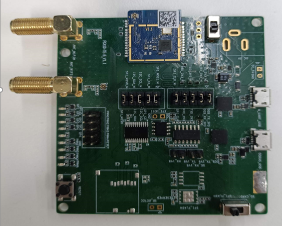
b. Connect the serial cable with the UART1 on the demo board as below
(baud rate: 115200)
![[]{#OLE_LINK8 .anchor}Figure 2: Establish a Serial Connection](./assets/rtos-development-guide/img/image5.jpeg)
Other Software Required to Develop and Debug Applications for the Device
None
Other Pre-requisites
None
Additional Software References
None
Set Up Hardware
UART1 can supply power and download image to board, so just connect the serial cable to UART1.
Setup AWS account and Permissions
To create an AWS account, see Create and Activate an AWS Account.
To add an IAM user to your AWS account, see IAM User Guide. To grant your IAM user account access to AWS IoT and FreeRTOS, attach the following IAM policies to your IAM user account:
AmazonFreeRTOSFullAccess
AWSIoTFullAccess
To attach the AmazonFreeRTOSFullAccess policy to your IAM user:
Browse to the IAM console, and from the navigation pane, choose Users.
Enter your user name in the search text box, and then choose it from the list.
Choose Add permissions.
Choose Attach existing policies directly.
In the search box, enter AmazonFreeRTOSFullAccess, choose it from the list, and then choose Next: Review.
Choose Add permissions.
To attach the AWSIoTFullAccess policy to your IAM user:
Browse to the IAM console, and from the navigation pane, choose Users.
Enter your user name in the search text box, and then choose it from the list.
Choose Add permissions.
Choose Attach existing policies directly.
In the search box, enter AWSIoTFullAccess, choose it from the list, and then choose Next: Review.
Choose Add permissions.
NOTE
The examples in this document are intended only for dev environments. All devices in your fleet must have credentials with privileges that authorize only intended actions on specific resources. The specific permission policies can vary for your use case. Identify the permission policies that best meet your business and security requirements. For more information, refer to Example policies and Security Best practices.
For more information about IAM and user accounts, see IAM User Guide.
For more information about policies, see IAM Permissions and Policies.
Provision the device with AWS IoT
Refer to Register your board manually.
Follow *steps 1--6* under the heading To create an AWS IoT policy. In step 1, note that the AWS region for your account can also be found in the drop-down between the account name and Support drop-downs in the top menu bar.
Follow *steps 1-10* under the heading To create an IoT thing, private key, and certificate for your device.
Download FreeRTOS
You can download the code from https://github.com/bekencorp/bk7231n_freertos_aws.git.
Configure FreeRTOS
Follow the instructions under the heading Configuring the FreeRTOS Demo.
Actually we only need to configure following things:
Need to acquire the key and certificate from AWS IoT (refer to above instructions)
generate the demos\include\aws_clientcredential_keys.h
Need to define the device thing name and endpoint, and Wi-Fi client credentials in the demos\include\aws_clientcredential.h.
Build the FreeRTOS Demo
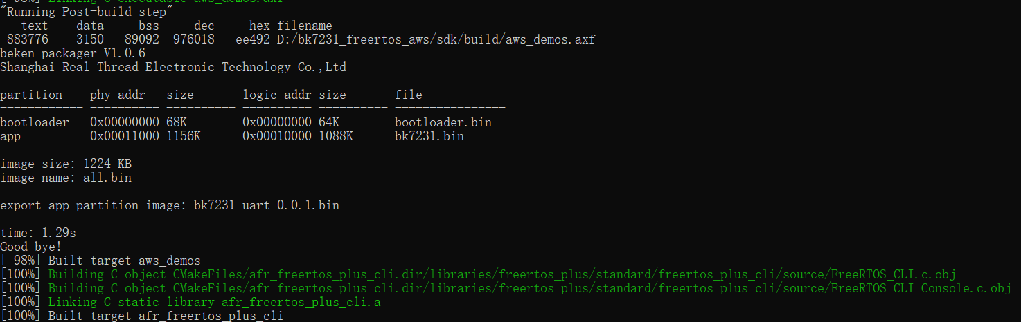
Execute the script: generate_make.bat, which will generate one
build folder automatically.cd build folder, and execute command: make, it will make all objects.
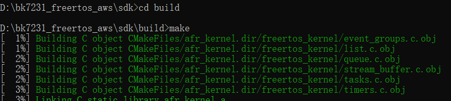
The final target image is: all.bin.
Run the FreeRTOS Demo Project
After building FreeRTOS demo and get the image successfully, open the flash tool projects\beken\tools\ bk_writer_v6.13.exe.
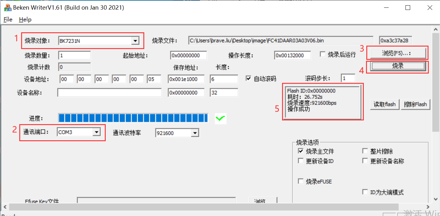
You can follow the below steps to flash image to board:
Choose the chip type: BK7231N
Choose the serial port, e.g, COM3
Click "浏览(F5)...:" to select the image file to download, e.g, all.bin
Click "烧录" to download image to board. Note that after click the "烧录" button, switch VCC "ON-OFF-ON" quickly. Do not need to click "读取flash" and "擦除flash", both are for debug.
After more than ten seconds, you can see the "操作成功".
To verify MQTT messages are being received by AWS IoT Core:
From the AWS IoT Core console at console.aws.amazon.com/iot, select Test from the navigation pane, and choose MQTT test client. Choose Subscribe to a topic and Enter the topic (or use the # wildcard to see all topics), then choose Subscribe. You should see messages being received. Below is the MQTT demo example message exported from AWS IoT core:
https://github.com/bekencorp/bk7231n_freertos_aws/blob/master/projects/beken/doc/subscription.json.
Also you can close this tool, and open one serial tool, then you can see the demo project logs, below is an example:
Debugging
When connecting the demo board with computer via serial tool, switch VCC to ON.
![[]{#_Toc101341065 .anchor}Figure 4: Switch VCC to ON](./assets/rtos-development-guide/img/image9.jpeg)
You should see following initial logs on the serial console:
prvHeapInit-start addr:0x409950, size:157360
[Flash]id:0xeb6015
--write status reg:4004,2.--
[Flash]init over
sctrl_sta_ps_init
SDK Rev: 3.0.36
cset:0 0 0 0
No TLV header found in flash
bandgap_calm_in_efuse=0x6b
[load]bandgap_calm=0x20->0x2b,vddig=4->5
[FUNC]rwnxl_init
IP Rev: W4-3.0.36-P0
[bk]tx_txdesc_flush
[FUNC]intc_init
[FUNC]calibration_main
get rfcali_mode:1
device_id=0x20521010
calibration_main over
NO TXPWR_TAB_TAB found in flash
Load default txpwr for b:0xd6b74
Load default txpwr for g:0xd6b82
fit n20 table with dist:4
Load default txpwr for n40:0xd6b90
Load default txpwr for ble:0xd6bd6
NO TXID found in flash, use def temp:330
temp in flash is:330
NO TXID found in flash, use lpf i&q:116, 116
NO TXID found in flash, use def xtal:38
xtal in flash is:38
xtal_cali:38
--init_xtal = 38
[FUNC]ps_init
int watchdog enabled, period=10000
task watchdog enabled, period=60000
[FUNC]func_init_extended OVER!!!
start_type:0
Initializing TCP/IP stack
bk_wlan_app_init finished
rf_thread_init ok
WIFI_On:166 conn_state=0
[sa_sta]MM_RESET_REQ
[bk]tx_txdesc_flush
[sa_sta]ME_CONFIG_REQ
[sa_sta]ME_CHAN_CONFIG_REQ
[sa_sta]MM_START_REQ
PSKC: ssid test, passphrase 12345678
sizeof(wpa_supplicant)=760
mm_add_if_req_handler:0
hapd_intf_add_vif,type:2, s:0, id:0
wpa_dInit
enter low level!
mac c8:47:8c:42:88:48
leave low level!
[net]addvif_idx:0
wpa_supplicant_req_scan
Setting scan request: 0.000000 sec
wpa_supplicant_scan
wpa_drv_scan
wpa_send_scan_req
no ht in scan
scan_start_req_handler
wpa_driver_scan_start_cb
0 504 [app] WiFi module initialized. Connecting to AP test
wpa_driver_scan_cb
Scan completed in 1.332000 seconds
get_scan_rst_null
WIFI_ConnectAP: conn_state=0 returnCode=1 ssid:test key:1234567 connect the WIFI AP
Troubleshooting
When IDT call the script to flash image to board to test, the script will start another CMD console automatically to flash image to board, sometimes it will hang on the "Getting the bus".
Please switch the VCC quickly "ON->OFF->ON"
Appendix Terms and Abbreviations
Terms and Abbreviations:
| Abbreviation | Description |
|---|---|
| AoA | Angle-of-arrival |
| AoD | Angle-of-departure |
| AP | Access Point |
| AWS | Amazon Web Service |
| BLE | Bluetooth Low Energy |
| BR | Basic Rate |
| CLI | Common Layer Interface |
| CMD | Command |
| EDR | Enhanced Data Rate |
| GPIO | General-Purpose Input /Output Ports |
| I2C | Inter-Integrated Circuit |
| ID | Identification |
| IDE | Integrated Development Environment |
| IDT | Intelligent Data Terminal |
| IoT | Item of Thing |
| IrDA | Infra-red Data Association |
| LED | Light Emitting Diode |
| MCU | Micro Control Unit |
| MQTT | Message Queuing Telemetry Transport Protocol |
| OTP | One Time Programable |
| PTA | Packet Traffic Arbitration |
| PWM | Pulse Width Modulation |
| RAM | Random Access Memory |
| RTOS | Real-time Operating System |
| SDIO | Secure Digital Input and Output |
| SDK | Software Development Kit |
| SPI | Software Process Improvement |
| TRNG | True Random Number Generator |
| UART | Universal Asynchronous Receiver/Transmitter |
| USB | Universal Serial Bus |
| VCC | Virtual Circuit Connection |
| WLAN | Wireless Local Area Networks |