

 English
Peripheral Interface Development Guide
Introduction
Quectel FLMx40D, FCMxx0D and FC41D modules support QuecOpen® solution. QuecOpen® is an embedded development platform based on RTOS system, which is intended to simplify the design and development of IoT applications. For more information on QuecOpen®, see Quick_Start_Guide.
This document is applicable to QuecOpen® solution based on SDK build environment. It outlines how to use GPIO, UART, SPI, I2C, ADC, and PWM APIs supported by the modules to develop corresponding peripheral interfaces in QuecOpen® solution.
NOTE
- The module supports two UARTs currently and these UARTs buffer data in FIFO mode by default.
- In SPI mode, the maximum frequency of the master device is 30 MHz, and the maximum frequency of the slave device is 10 MHz.
Applicable Modules
| Module Family | Module |
|---|---|
| FC41D | |
| FCMxx0D | FCM100D |
| FCM740D | |
| FLMx40D | FLM040D |
| FLM140D | |
| FLM240D | |
| FLM340D |
GPIO API
Header File
ql_gpio.h, the header file of GPIO API, is in ql_components/qadpt/include/ directory. Unless otherwise specified, all header files mentioned in this document are in this directory.
API Description
ql_gpio_init
This function initializes the GPIO.
- Prototype
ql_gpio_errcode_e ql_gpio_init(ql_gpio_num_e gpio_num, ql_gpio_mode_e mode)
- Parameter
gpio_num:
[In] GPIO pin number. See ql_gpio_num_e for details.
mode:
[In] GPIO mode. See ql_gpio_mode_e for details.
- Return Value
Result code. See ql_gpio_errcode_e for details.
ql_gpio_num_e
The enumeration of GPIO pin numbers:
typedef enum
{
  QL_GPIO0 = 0,
  QL_GPIO1,
  QL_GPIO6 = 6,
  QL_GPIO7,
  QL_GPIO8,
  QL_GPIO9,
  QL_GPIO10,
  QL_GPIO11,
  QL_GPIO14 = 14,
  QL_GPIO15,
  QL_GPIO16,
  QL_GPIO17,
  QL_GPIO20 = 20,
  QL_GPIO21,
  QL_GPIO22,
  QL_GPIO23,
  QL_GPIO24,
  QL_GPIO26 = 26,
  QL_GPIO28 = 28,
} ql_gpio_num_e;
- Member
| Member | Description |
|---|---|
| QL_GPIO0 | GPIO0 |
| QL_GPIO1 | GPIO1 |
| QL_GPIO6 | GPIO6 |
| QL_GPIO7 | GPIO7 |
| QL_GPIO8 | GPIO8 |
| QL_GPIO9 | GPIO9 |
| QL_GPIO10 | GPIO10 |
| QL_GPIO11 | GPIO11 |
| QL_GPIO14 | GPIO14 |
| QL_GPIO15 | GPIO15 |
| QL_GPIO16 | GPIO16 |
| QL_GPIO17 | GPIO17 |
| QL_GPIO20 | GPIO20 |
| QL_GPIO21 | GPIO21 |
| QL_GPIO22 | GPIO22 |
| QL_GPIO23 | GPIO23 |
| QL_GPIO24 | GPIO24 |
| QL_GPIO26 | GPIO26 |
| QL_GPIO28 | GPIO28 |
ql_gpio_mode_e
The enumeration of GPIO modes:
typedef enum
{
  QL_GMODE_INPUT_PULLDOWN = 0,
  QL_GMODE_OUTPUT,
  QL_GMODE_SECOND_FUNC,
  QL_GMODE_INPUT_PULLUP,
  QL_GMODE_INPUT,
  QL_GMODE_SECOND_FUNC_PULL_UP, //Special for uart1
  QL_GMODE_OUTPUT_PULLUP,
  QL_GMODE_SET_HIGH_IMPENDANCE,
  QL_GMODE_DEEP_PS,
} ql_gpio_mode_e;
- Member
| Member | Description |
|---|---|
| QL_GMODE_INPUT_PULLDOWN | Input is configured for pull-down |
| QL_GMODE_OUTPUT | Output is configured for push-pull |
| QL_GMODE_SECOND_FUNC | Second functionality of the GPIO |
| QL_GMODE_INPUT_PULLUP | Input is configured for pull-up |
| QL_GMODE_INPUT | Input is configured for floating |
| QL_GMODE_SECOND_FUNC_PULL_UP | Pull up the second functionality of the pin (Only available for UART1) |
| QL_GMODE_OUTPUT_PULLUP | Output is configured for pull-up (Not supported currently) |
| QL_GMODE_SET_HIGH_IMPENDANCE | High impedance |
| QL_GMODE_DEEP_PS | High impedance |
ql_gpio_errcode_e
The enumeration of GPIO API result codes:
typedef enum
{
  QL_GPIO_SUCCESS = 0,
  QL_GPIO_EXECUTE_ERR,
  QL_GPIO_INVALID_PARAM_ERR,
} ql_gpio_errcode_e;
- Member
| Member | Description |
|---|---|
| QL_GPIO_SUCCESS | Successful execution |
| QL_GPIO_EXECUTE_ERR | Failed execution |
| QL_GPIO_INVALID_PARAM_ERR | Invalid parameter |
ql_gpio_set_level
This function sets the pin level of the specified GPIO. It is valid only for output pins.
- Prototype
ql_gpio_errcode_e ql_gpio_set_level(ql_gpio_num_e gpio_num, ql_gpio_output_level_e output_level)
- Parameter
gpio_num:
[In] GPIO pin number. See ql_gpio_num_e for details.
output_level:
[In] Pin level only for output pins. See ql_gpio_output_level_e for details.
- Return Value
Result code. See ql_gpio_errcode_e for details.
ql_gpio_output_level_e
The enumeration of GPIO output levels:
typedef enum
{
  QL_GPIO_OUTPUT_LOW = 0,
  QL_GPIO_OUTPUT_HIGH,
} ql_gpio_output_level_e;
- Member
| Member | Description |
|---|---|
| QL_GPIO_OUTPUT_LOW | Low level |
| QL_GPIO_OUTPUT_HIGH | High level |
ql_gpio_set_level_reverse
This function reverses the GPIO output level. It is valid only for output pins.
- Prototype
ql_gpio_errcode_e ql_gpio_set_level_reverse(ql_gpio_num_e gpio_num)
- Parameter
gpio_num:
[In] GPIO pin number. See ql_gpio_num_e for details.
- Return Value
Result code. See ql_gpio_errcode_e for details.
ql_gpio_get_level
This function gets the pin level of the specified GPIO.
- Prototype
ql_gpio_errcode_e ql_gpio_get_level(ql_gpio_num_e gpio_num, UINT32 *input_level)
- Parameter
gpio_num:
[In] GPIO pin number. See ql_gpio_num_e for details.
input_level:
[Out] Pin level value.
- Return Value
Result code. See ql_gpio_errcode_e for details.
ql_gpio_int_init
This function initializes and enables the GPIO interrupt.
- Prototype
ql_gpio_errcode_e ql_gpio_int_init(ql_gpio_num_e gpio_num, ql_gpio_irq_trigger_e trigger, ql_gpio_irq_callback calback)
- Parameter
gpio_num:
[In] GPIO pin number. See ql_gpio_num_e for details.
trigger:
[In] GPIO interrupt triggering mode. See ql_gpio_irq_trigger_e for details.
calback:
[In] GPIO interrupt callback function. See ql_gpio_irq_callback for details.
- Return Value
Result code. See ql_gpio_errcode_e for details.
ql_gpio_irq_trigger_e
The enumeration of GPIO interrupt triggering modes:
typedef enum
{
  QL_IRQ_TRIGGER_LOW_LEVEL = 0x0,
  QL_IRQ_TRIGGER_HGIH_LEVEL,
  QL_IRQ_TRIGGER_RISING_EDGE,
  QL_IRQ_TRIGGER_FALLING_EDGE,
} ql_gpio_irq_trigger_e;
- Member
| Member | Description |
|---|---|
| QL_IRQ_TRIGGER_LOW_LEVEL | Pin interrupt triggered at low level |
| QL_IRQ_TRIGGER_HGIH_LEVEL | Pin interrupt triggered at high level |
| QL_IRQ_TRIGGER_RISING_EDGE | Pin interrupt triggered at rising edge |
| QL_IRQ_TRIGGER_FALLING_EDGE | Pin interrupt triggered at falling edge |
ql_gpio_irq_callback
This is the callback function of GPIO interrupt.
- Prototype
typedef void (*ql_gpio_irq_callback)(void *arg)
- Parameter
arg:
[In] Pin for triggering the interrupt.
ql_gpio_int_disable
This function disables the configured GPIO interrupt.
- Prototype
ql_gpio_errcode_e ql_gpio_int_disable(ql_gpio_num_e gpio_num)
- Parameter
gpio_num:
[In] GPIO pin number. See ql_gpio_num_e for details.
- Return Value
Result code. See ql_gpio_errcode_e for details.
GPIO Development Process
This chapter explains how to use the above GPIO API to configure GPIO and perform basic debugging. The following subsections take QL_GPIO6 as an example.
GPIO Operation
The example of how to operate the GPIO is provided in the module SDK. The demo is in ql_gpio_demo.c file in the ql_application/quectel_demo directory. The descriptions of related functions are as follows:
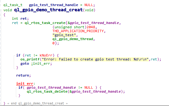
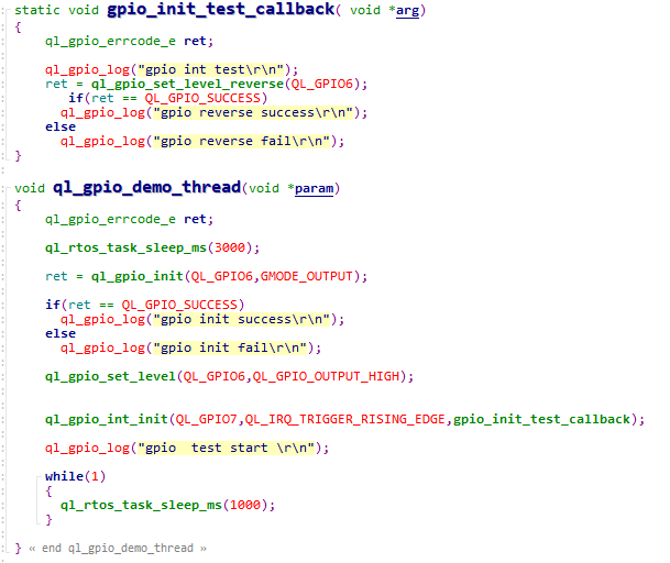
ql_gpio_demo_thread_creat(): This function creates GPIO tasks. You need to call this function to run demo.ql_gpio_demo_thread(): This function executes the task. It implements GPIO initialization, output level configuration and interrupt triggering functionalities.
To run the demo, enable the macro definitions CFG_ENABLE_QUECTEL_DEMO and CFG_ENABLE_QUECTEL_GPIO. This will automatically trigger the execution of ql_gpio_demo_thread_creat() and ql_gpio_demo_thread() to create a test task.
Function Debugging
You need to use the development board (Take FC41D TE-B as an example) with the module to debug the GPIO function. Follow these steps for debugging:
Run the GPIO demo as explained in GPIO Operation.
Recompile the firmware version and flash it to the module.
Reboot the module.
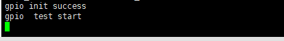
Open UART 2 to obtain the debugging log. The log information will be displayed as follows:
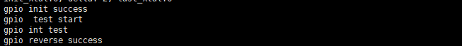
If the following information is displayed during the debugging, it indicates the GPIO interrupt has been triggered.
UART API
Header File
ql_uart.h, the header file of GPIO API, is in the ql_components/qadpt/include/ directory. Unless otherwise specified, all header files mentioned in this document are in this directory.
API Description
ql_uart_set_dcbconfig
This function sets the UART properties. The UART properties take effect after the UART is reopened.
- Prototype
ql_uart_errcode_e ql_uart_set_dcbconfig(ql_uart_port_number_e port, ql_uart_config_s *dcb)
- Parameter
port:
[In] UART number. See ql_uart_port_number_e for details.
dcb:
[In] Configuration of UART properties. See ql_uart_config_s for details.
- Return Value
Result code. See ql_uart_errcode_e for details.
ql_uart_port_number_e
The enumeration of UART numbers. The module currently supports only two UARTs.
typedef enum
{
  QL_UART_PORT_1,
  QL_UART_PORT_2,
} ql_uart_port_number_e;
- Member
| Member | Description |
|---|---|
| QL_UART_PORT_1 | UART 1 |
| QL_UART_PORT_2 | UART 2 |
ql_uart_config_s
The structure of the configuration of UART properties:
typedef struct
{
  ql_uart_baud_e baudrate;
  ql_uart_databit_e data_bit;
  ql_uart_stopbit_e stop_bit;
  ql_uart_parityit_e parity_bit;
  ql_uart_flowctrl_e flow_ctrl;
} ql_uart_config_s;
- Parameter
| Type | Parameter | Description |
|---|---|---|
| ql_uart_baud_e | baudrate | Baud rate. Default: 115200 bps. See ql_uart_baud_e for details. |
| ql_uart_databit_e | data_bit | Data bit. Default: 8 bits. See ql_uart_databit_e for details. |
| ql_uart_stopbit_e | stop_bit | Stop bit. Default: 1 bit. See ql_uart_stopbit_e for details. |
| ql_uart_parityit_e | parity_bit | Parity bit. Default: No parity bit. See ql_uart_parityit_e for details. |
| ql_uart_flowctrl_e | flow_ctrl | Flow control. Default: Disabled. See ql_uart_flowctrl_e for details. |
ql_uart_baud_e
The enumeration of baud rates:
typedef enum
{
  QL_UART_BAUD_1200 = 1200,
  QL_UART_BAUD_2400 = 2400,
  QL_UART_BAUD_4800 = 4800,
  QL_UART_BAUD_9600 = 9600,
  QL_UART_BAUD_14400 = 14400,
  QL_UART_BAUD_19200 = 19200,
  QL_UART_BAUD_28800 = 28800,
  QL_UART_BAUD_33600 = 33600,
  QL_UART_BAUD_38400 = 38400,
  QL_UART_BAUD_57600 = 57600,
  QL_UART_BAUD_115200 = 115200,
  QL_UART_BAUD_230400 = 230400,
  QL_UART_BAUD_460800 = 460800,
  QL_UART_BAUD_921600 = 921600,
  QL_UART_BAUD_1000000 = 1000000,
  QL_UART_BAUD_2000000 = 2000000,
} ql_uart_baud_e;
- Member
| Member | Description |
|---|---|
| QL_UART_BAUD_1200 | 1200 bps |
| QL_UART_BAUD_2400 | 2400 bps |
| QL_UART_BAUD_4800 | 4800 bps |
| QL_UART_BAUD_9600 | 9600 bps |
| QL_UART_BAUD_14400 | 14400 bps |
| QL_UART_BAUD_19200 | 19200 bps |
| QL_UART_BAUD_28800 | 28800 bps |
| QL_UART_BAUD_33600 | 33600 bps |
| QL_UART_BAUD_38400 | 38400 bps |
| QL_UART_BAUD_57600 | 57600 bps |
| QL_UART_BAUD_115200 | 115200 bps |
| QL_UART_BAUD_230400 | 230400 bps |
| QL_UART_BAUD_460800 | 460800 bps |
| QL_UART_BAUD_921600 | 921600 bps |
| QL_UART_BAUD_1000000 | 1000000 bps |
| QL_UART_BAUD_2000000 | 2000000 bps |
ql_uart_databit_e
The enumeration of data bits:
typedef enum
{
  QL_UART_DATABIT_5 = 0,
  QL_UART_DATABIT_6,
  QL_UART_DATABIT_7,
  QL_UART_DATABIT_8,
} ql_uart_databit_e;
- Member
| Member | Description |
|---|---|
| QL_UART_DATABIT_5 | 5 bits |
| QL_UART_DATABIT_6 | 6 bits |
| QL_UART_DATABIT_7 | 7 bits |
| QL_UART_DATABIT_8 | 8 bits |
ql_uart_stopbit_e
The enumeration of stop bits:
typedef enum
{
  QL_UART_STOP_1 = 0,
  QL_UART_STOP_2,
} ql_uart_stopbit_e;
- Member
| Member | Description |
|---|---|
| QL_UART_STOP_1 | 1 bit |
| QL_UART_STOP_2 | 2 bits |
ql_uart_parityit_e
The enumeration of parity bits:
typedef enum
{
  QL_UART_PARITY_NONE,
  QL_UART_PARITY_ODD,
  QL_UART_PARITY_EVEN,
} ql_uart_parityit_e;
- Member
| Member | Description |
|---|---|
| QL_UART_PARITY_NONE | No parity |
| QL_UART_PARITY_ODD | Odd parity |
| QL_UART_PARITY_EVEN | Even parity |
ql_uart_flowctrl_e
The enumeration of flow control types:
typedef enum
{
  QL_FC_NONE = 0,
  QL_FC_HW_CTS,
  QL_FC_HW_RTS,
  QL_FC_HW_RTS_CTS,
} ql_uart_flowctrl_e;
- Member
| Member | Description |
|---|---|
| QL_FC_NONE | No flow control |
| QL_FC_HW_CTS | Hardware CTS |
| QL_FC_HW_RTS | Hardware RTS |
| QL_FC_HW_RTS_CTS | Hardware CTS and RTS |
ql_uart_errcode_e
The enumeration of result codes:
typedef enum
{
  QL_UART_SUCCESS = 0,
  QL_UART_EXECUTE_ERR,
  QL_UART_MEM_ADDR_NULL_ERR,
  QL_UART_INVALID_PARAM_ERR,
  QL_UART_NOT_OPEN_ERR,
} ql_uart_errcode_e;
- Member
| Member | Description |
|---|---|
| QL_UART_SUCCESS | Successful execution |
| QL_UART_EXECUTE_ERR | Failed execution |
| QL_UART_MEM_ADDR_NULL_ERR | Parameter address: Null |
| QL_UART_INVALID_PARAM_ERR | Invalid parameter |
| QL_UART_NOT_OPEN_ERR | UART is not open |
ql_uart_get_dcbconfig
This function gets the configuration of UART properties.
- Prototype
ql_uart_errcode_e ql_uart_get_dcbconfig(ql_uart_port_number_e port, ql_uart_config_s *dcb)
- Parameter
port:
[In] UART number. See ql_uart_port_number_e for details.
dcb:
[In] Configuration of UART properties. See in ql_uart_config_s for details.
- Return Value
Result code. See in ql_uart_errcode_e for details.
ql_uart_open
This function opens the UART.
- Prototype
ql_uart_errcode_e ql_uart_open(ql_uart_port_number_e port)
- Parameter
port:
[In] UART number. See ql_uart_port_number_e for details.
- Return Value
Result code. See ql_uart_errcode_e for details.
ql_uart_close
This function closes the UART.
- Prototype
ql_uart_errcode_e ql_uart_close(ql_uart_port_number_e port)
- Parameter
port:
[In] UART number. See ql_uart_port_number_e for details.
- Return Value
Result code. See ql_uart_errcode_e for details.
ql_uart_write
This function writes data to the module through the UART.
- Prototype
int ql_uart_write(ql_uart_port_number_e port, unsigned char *data, unsigned int data_len)
- Parameter
port:
[In] UART number. See ql_uart_port_number_e for details.
data:
[In] Written data.
data_len:
[In] Length of written data.
- Return Value
Result code. See ql_uart_errcode_e for details.
ql_uart_read
This function reads the data from the module through the UART.
- Prototype
int ql_uart_read(ql_uart_port_number_e port, unsigned char *data, unsigned int data_len)
- Parameter
port:
[In] UART number. See ql_uart_port_number_e for details.
data:
[Out] Read data.
data_len:
[In] Length of read data.
- Return Value
Result code. See ql_uart_errcode_e for details.
ql_uart_set_rx_cb
This function registers the callback function triggered by the UART receiving data interrupt.
- Prototype
ql_uart_errcode_e ql_uart_set_rx_cb(ql_uart_port_number_e port, ql_uart_callback uart_cb)
- Parameter
port:
[In] UART number. See ql_uart_port_number_e for details.
uart_cb:
[In] Callback function to be registered. See in ql_uart_callback for details.
- Return Value
Result code. See ql_uart_errcode_e for details.
ql_uart_callback
This is the callback function of the UART interrupt.
- Prototype
typedef void (*ql_uart_callback)(int uport, void *param);
- Parameter
uport:
[In] UART number. See ql_uart_port_number_e for details.
param:
[In] Input parameter.
- Return Value
None
ql_uart_set_tx_int
This function sets the interrupt event that is triggered upon completion of data transmission.
- Prototype
ql_uart_errcode_e ql_uart_set_tx_int(ql_uart_port_number_e port, unsigned int set)
- Parameter
port:
[In] UART number. See ql_uart_port_number_e for details.
set:
[In] Control the interrupt event
1 Enable interrupt
2 Disable interrupt
- Return Value
Result code. See ql_uart_errcode_e for details.
ql_uart_set_tx_cb
This function registers the callback function triggered when the UART initiates a data transmission.
- Prototype
ql_uart_errcode_e ql_uart_set_tx_cb(ql_uart_port_number_e port, ql_uart_callback uart_cb)
- Parameter
port:
[In] UART number. See ql_uart_port_number_e for details.
uart_cb:
[In] Callback function to be registered. See ql_uart_callback for details.
- Return Value
Result code. See ql_uart_errcode_e for details.
UART Development Process
This chapter explains how to use the above UART API in the application and perform basic debugging. The following subsections take UART 1 as an example.
UART Operation
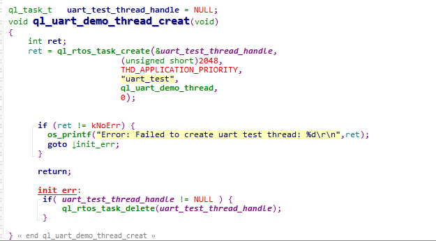
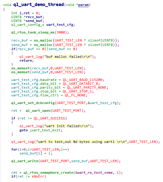
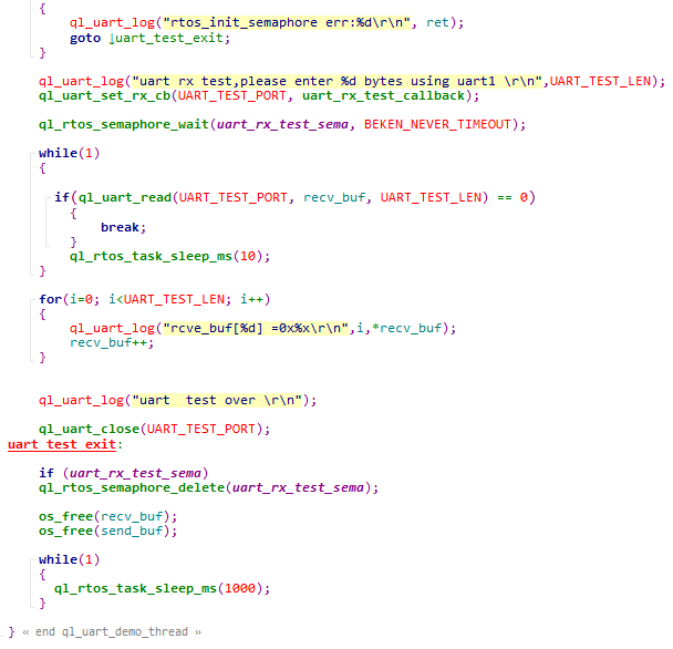
The example of how to operate the UART is provided in the module SDK. The demo is in ql_uart_demo.c file in the ql_application/quectel_demo directory. The descriptions of related functions are as follows:
ql_uart_demo_thread_creat(): This function creates a UART task. You need to call this function to run the demo.ql_uart_demo_thread(): This function executes the task. It initializes the UART, sends, and receives data.
To run the demo, enable CFG_ENABLE_QUECTEL_DEMO and CFG_ENABLE_QUECTEL_UART. This will automatically trigger the execution of ql_uart_demo_thread_creat() and ql_uart_demo_thread() to create a task.
Function Debugging
You need to use the development board (Take FC41D TE-B as an example) with the module to debug the UART function. Follow these steps for debugging:
Run the UART demo as explained in UART Operation.
Recompile the firmware version and flash it to the module.
Reboot the module.
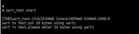
Open UART 1 to start the test.
Open UART 2 to obtain log information. The log information will be displayed as follows:
The data received by UART 1:
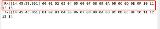
After a successful UART data reception test is completed, send twenty bytes of data with the UART tool to UART 1, as shown in the figure below:
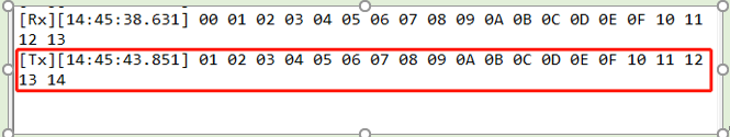
The information printed from UART 2 is shown as follows:
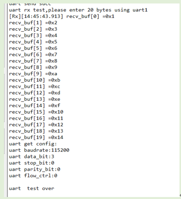
It can be seen that the UART function has been tested successfully by comparing the sent data in *Figure 10* with the received data in *Figure 11*.
SPI API
For this module, SPI data are transferred in the DMA mode.
Header File
ql_spi.h, the header file of SPI API, is in ql_components/qadpt/include/ directory. Unless otherwise specified, all header files mentioned in this document are in this directory.
API Description
ql_spi_init
This function initializes SPI and must be called before using other SPI functions.
- Prototype
ql_spi_errcode_e ql_spi_init(ql_spi_config_s spi_cfg, ql_spi_messag_s *spi_msg)
- Parameter
spi_cfg:
[In] SPI configuration. See ql_spi_config_s for details.
spi_msg:
[In] Data sent or received via SPI. See ql_spi_messag_s for details.
- Return Value
Result code. See ql_spi_errcode_e for details.
ql_spi_config_s
The structure of SPI configuration:
typedef struct
{
  UINT32 spiclk;
  ql_spi_cpol_pol_e cpol;
  ql_spi_cpha_pol_e cpha;
  ql_spi_transfer_mode_e transmode;
  ql_spi_master_slave_mode_e masterorslave;
} ql_spi_config_s;
- Parameter
| Type | Parameter | Description |
|---|---|---|
| UINT32 | spiclk | SPI clock frequency. Maximum value: 30 MHz |
| ql_spi_cpol_pol_e | cpol | SPI clock polarity. See ql_spi_cpol_pol_e for details. |
| ql_spi_cpha_pol_e | cpha | SPI clock phase. See ql_spi_cpha_pol_e for details. |
| ql_spi_transfer_mode_e | transmode | SPI transmitting mode. See ql_spi_transfer_mode_e for details. |
| ql_spi_master_slave_mode_e | masterorslave | SPI master or slave selection. See ql_spi_master_slave_mode_e for details. |
ql_spi_cpol_pol_e
The enumeration of SPI clock polarities:
typedef enum
{
  QL_SPI_CPOL_LOW = 0,
  QL_SPI_CPOL_HIGH,
} ql_spi_cpol_pol_e
- Member
| Member | Description |
|---|---|
| QL_SPI_CPOL_LOW | SCK is at a low level during idle state |
| QL_SPI_CPOL_HIGH | SCK is at a high level during idle state |
ql_spi_cpha_pol_e
The enumeration of SPI clock phases:
typedef enum
{
  QL_SPI_CPHA_1Edge,
  QL_SPI_CPHA_2Edge,
}ql_spi_cpha_pol_e;
- Member
| Member | Description |
|---|---|
| QL_SPI_CPHA_1Edge | Sample data on the edge of the first period of SCK |
| QL_SPI_CPHA_2Edge | Sample data on the edge of the second period of SCK |
ql_spi_transfer_mode_e
The enumeration of SPI transmitting modes:
typedef enum {
  QL_SPI_MSB = 0,
  QL_SPI_LSB,
} ql_spi_transfer_mode_e;
- Member
| Member | Description |
|---|---|
| QL_SPI_MSB | MSB is sent first |
| QL_SPI_LSB | LSB is sent first |
ql_spi_master_slave_mode_e
The enumeration of SPI master or slave selections:
typedef enum {
  QL_SPI_MASTER = 0,
  QL_SPI_SLAVE,
} ql_spi_master_slave_mode_e;
- Member
| Member | Description |
|---|---|
| QL_SPI_MASTER | SPI is master |
| QL_SPI_SLAVE | SPI is slave |
ql_spi_messag_s
The structure of data sent or received via SPI:
typedef struct {
  UINT8 *send_buf;
  UINT32 send_len;
  UINT8 *recv_buf;
  UINT32 recv_len;
} ql_spi_messag_s;
- Parameter
| Type | Parameter | Description |
|---|---|---|
| UINT8 | send_buf | Sent data |
| UINT32 | send_len | Sent data length |
| UINT8 | recv_buf | Received data |
| UINT32 | recv_len | Received data length |
ql_spi_errcode_e
The enumeration of SPI result codes:
typedef enum {
  QL_SPI_SUCCESS = 0,
  QL_SPI_EXECUTE_ERR,
} ql_spi_errcode_e;
- Member
| Member | Description |
|---|---|
| QL_SPI_SUCCESS | Successful execution |
| QL_SPI_EXECUTE_ERR | Failed execution |
ql_spi_transfer
This function sends and receives SPI data, and the sending mode or receiving mode depends on the configuration of the ql_spi_messag_s() structure.
- Prototype
ql_spi_errcode_e ql_spi_transfer(ql_spi_messag_s *spi_msg)
- Parameter
spi_msg:
[In] Data sent or received via SPI. See ql_spi_messag_s for details.
- Return Value
Result code. See ql_spi_errcode_e for details.
SPI Development Process
This chapter explains how to use the above SPI API in applications, and perform basic debugging, and test data transmission from the master.
SPI Operation
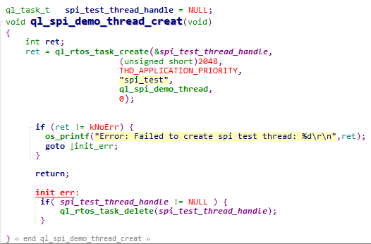
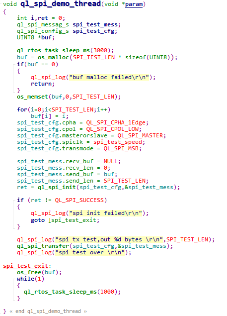
The example of how to operate the SPI is provided in the module SDK. The demo is in ql_spi_demo.c file in the ql_application/quectel_demo directory. The descriptions of related functions are as follows:
ql_spi_demo_thread_creat(): Creates an SPI task. This function needs to be called to run the SPI demo.ql_spi_demo_thread(): This function executes the task. It initializes DMA and sends data via SPI.
To run this example, you need to enable the CFG_ENABLE_QUECTEL_DEMO and CFG_ENABLE_QUECTEL_SPI macro definitions, while simultaneously disabling the CFG_SUPPORT_SPI_FLASH_TEST macro definition. This will automatically trigger the execution of ql_spi_demo_thread_creat() and ql_spi_demo_thread() to create a test task.
Function Debugging
You need to use the development board (Take FC41D TE-B as an example) with the module to debug the SPI function. Follow these steps for debugging:
Run the SPI demo as explained in SPI Operation.
Recompile the firmware version and flash it to the module.
Reboot the module.
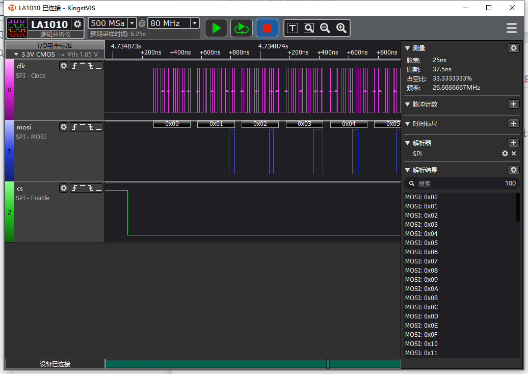
Capture waveforms through the logic analyzer.
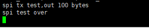
Open UART 2 to obtain log information. The log information will be displayed as follows.
I2C API
Header File
ql_i2c1_eeprom.h, the header file of I2C API, is in ql_components/qadpt/include/ directory. Unless otherwise specified, all header files mentioned in this document are in this directory.
API Description
ql_I2cInit
This function initializes the I2C bus.
- Prototype
int ql_I2cInit(DD_HANDLE* i2c_hdl, ql_i2c_mode_e Mode)
- Parameter
i2c_hdl:
[Out] Obtained I2C handle.
Mode:
[In] Work mode of I2C. See ql_i2c_mode_e for details.
- Return Value
Result code. See ql_errcode_i2c_e for details.
ql_i2c_mode_e
The enumeration of I2C operation modes:
typedef enum
{
  STANDARD_MODE = 0,
  FAST_MODE = 1,
} ql_i2c_mode_e
- Member
| Member | Description |
|---|---|
| STANDARD_MODE | Standard mode |
| FAST_MODE | Fast mode |
ql_errcode_i2c_e
The enumeration of I2C result codes:
typedef enum
{
  QL_I2C_SUCCESS =0,
  QL_I2C_INIT_ERR ,
  QL_I2C_WRITE_ERR,
  QL_I2C_READ_ERR,
  QL_I2C_RELEASE_ERR,
} ql_errcode_i2c_e
- Member
| Member | Description |
|---|---|
| QL_I2C_SUCCESS | Successful execution |
| QL_I2C_INIT_ERR | Failed I2C initialization |
| QL_I2C_WRITE_ERR | Failed to write data to I2C |
| QL_I2C_READ_ERR | Failed to read data from I2C |
| QL_I2C_RELEASE_ERR | Failed to release I2C |
ql_I2cWrite
This function writes data to the I2C bus.
- Prototype
int ql_I2cWrite(DD_HANDLE i2c_hdl, UINT8 slave, UINT16 addr, char *data, UINT32 length, UINT8 addr_width)
- Parameter
i2c_hdl:
[In] I2C handle.
slave:
[In] I2C slave device address.
addr:
[In] I2C slave register address.
data:
[In] Data to be written to the I2C bus.
length:
[In] Data length to be written to the I2C bus.
addr_width:
[In] Length of the slave register address.
- Return Value
Result code. See ql_errcode_i2c_e for details.
ql_I2cRead
This function reads data from the I2C bus.
- Prototype
int ql_I2cRead(DD_HANDLE i2c_hdl, UINT8 slave, UINT16 addr, char *buf, UINT32 length, UINT8 addr_width)
- Parameter
i2c_hdl:
[In] I2C handle.
slave:
[In] I2C slave device address.
addr:
[In] I2C slave register address.
buf:
[Out] Data read from the I2C bus.
length:
[In] Data length read from the I2C bus.
addr_width:
[In] Length of the slave register address.
- Return Value
Result code. See ql_errcode_i2c_e for details.
ql_I2cRelease
This function releases the I2C bus. To reinitialize the same I2C host, call this function to release the I2C bus, and then call ql_I2cInit() again to initialize the I2C bus.
- Prototype
int ql_I2cRelease(DD_HANDLE i2c_hdl)
- Parameter
i2c_hdl:
[In] I2C handle.
- Return Value
Result code. See ql_errcode_i2c_e for details.
Example
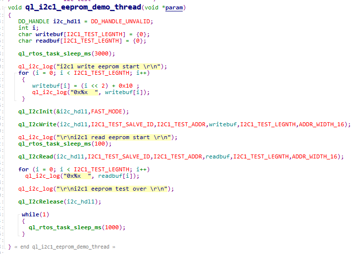
The example of how to use the I2C is provided in the module SDK. The demo is in ql_i2c_eeprom_demo.c file in the ql_application/quectel_demo directory. I2C uses peripherals for communication. EEPROM chip (Model: FM24C128A) is applied in this example. Related functions are described below:
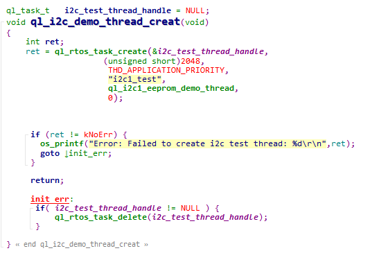
ql_i2c_demo_thread_creat(): This function creates an I2C tasks. You need to call this function to run the demo.ql_i2c1_eeprom_demo_thread(): This function executes the task. It initializes I2C peripherals, writes data, reads data, and releases the I2C bus.
To run this demo, enable the CFG_ENABLE_QUECTEL_DEMO and CFG_ENABLE_QUECTEL_I2C1 macro definitions. This will automatically trigger the execution of ql_i2c_demo_thread_creat() and ql_i2c1_eeprom_demo_thread() to create a test task.
ADC API
Header File
ql_adc.h, the header file of ADC API, is in the
ql_components/qadpt/include/ directory. Unless otherwise specified, all header files mentioned in this document are in this directory.
API Description
ql_adc_thread_init
This function creates the ADC task.
- Prototype
ql_adc_errcode_e ql_adc_thread_init(void)
- Parameter
None
- Return Value
Result code. See ql_adc_errcode_e for details.
ql_adc_errcode_e
The enumeration of ADC result codes:
typedef enum
{
  QL_ADC_SUCCESS = 0,
  QL_ADC_EXECUTE_ERR,
  QL_ADC_INVALID_PARAM_ERR,
} ql_adc_errcode_e
- Parameter
| Parameter | Description |
|---|---|
QL_ADC_SUCCESS |
Successful execution |
QL_ADC_EXECUTE_ERR |
Failed execution |
QL_ADC_INVALID_PARAM_ERR |
Invalid parameter |
ql_adc_channel_init
This function configures ADC channel parameters.
- Prototype
ql_adc_errcode_e ql_adc_channel_init(ql_adc_obj_s *handle, ql_adc_obj_callback cb, ql_adc_channel_e channel, void *user_data)
- Parameter
handle:
[In] ADC channel. See ql_adc_obj_s for details.
cb:
[In] Callback function for channel detection. See ql_adc_obj_callback for details.
channel:
[In] ADC channel number. See ql_adc_channel_e for details.
user_data:
[In] User data.
- Return Value
Result code. See ql_adc_errcode_e for details.
ql_adc_obj_s
The structure of ADC channel:
typedef struct adc_obj_ {
  void *user_data;
  ql_adc_channel_e channel;
  ql_adc_obj_callback cb;
  struct adc_obj_ *next;
} ql_adc_obj_s
- Parameter
| Type | Parameter | Description |
|---|---|---|
| void | user_data | User data |
| ql_adc_channel_e | channel | ADC channel number. See ql_adc_channel_e for details. |
| ql_adc_obj_callback | cb | Callback function for channel detection |
| struct adc_obj_ | next | Address of the next node of the Linked List |
ql_adc_obj_callback
This function is the callback function for ADC channel detection.
- Prototype
typedef void (*ql_adc_obj_callback)(int new_mv, void *user_data)
- Parameter
new_mv:
[In] Detected voltage range (0--2400 mV).
user_data:
[In] User data.
- Return Value
None
ql_adc_channel_e
The enumeration of ADC channel numbers.
typedef enum
{
  QL_ADC_CHANNEL_0 = 0,
  QL_ADC_CHANNEL_1,
  QL_ADC_CHANNEL_2,
  QL_ADC_CHANNEL_3,
  QL_ADC_CHANNEL_4,
  QL_ADC_CHANNEL_5,
  QL_ADC_CHANNEL_6,
} ql_adc_channel_e
- Parameter
| Parameter | Description |
|---|---|
| QL_ADC_CHANNEL_0 | Channel 0, detects voltage for VBAT pin, which is at half the VBAT voltage |
| QL_ADC_CHANNEL_1 | Channel 1, detects voltage from GPIO26 |
| QL_ADC_CHANNEL_2 | Channel 2, detects voltage from GPIO24 |
| QL_ADC_CHANNEL_3 | Channel 3, detects voltage from GPIO23 |
| QL_ADC_CHANNEL_4 | Channel 4, detects voltage from GPIO28 |
| QL_ADC_CHANNEL_5 | Channel 5, detects voltage from GPIO22 |
| QL_ADC_CHANNEL_6 | Channel 6, detects voltage from GPIO21 |
ql_adc_channel_start
This function enables ADC detection.
- Prototype
ql_adc_errcode_e ql_adc_channel_start(ql_adc_obj_s *handle)
- Parameter
handle:
[In] ADC channel. See ql_adc_obj_s for details.
- Return Value
Result code. See ql_adc_errcode_e for details.
ql_adc_channel_stop
This function stops ADC detection.
- Prototype
ql_adc_errcode_e ql_adc_channel_stop(ql_adc_obj_s *handle)
- Parameter
handle:
[In] ADC channel. See ql_adc_obj_s for details.
- Return Value
Result code. See ql_adc_errcode_e for details.
ADC Development Process
This chapter explains how to use the above ADC API in applications, and perform basic debugging. The following subsections take channel 1 as an example.
ADC Operation
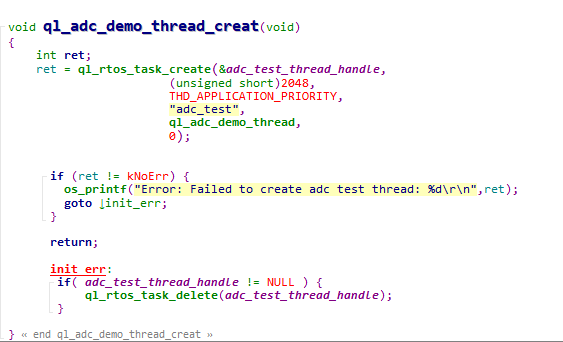
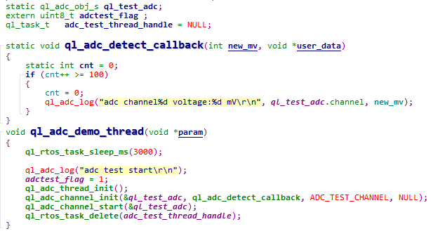
The example of how to operate the ADC is provided in the module SDK. The demo is in ql_adc_demo.c file in the ql_application/quectel_demo directory. The descriptions of related functions are as follows:
ql_adc_demo_thread_creat(): Creates an ADC task. This function needs to be called to run the ADC demo.ql_adc_demo_thread(): This function executes the task. It initializes ADC and detects voltage.
To run this example, just enable the CFG_ENABLE_QUECTEL_DEMO and CFG_ENABLE_QUECTEL_ADC macro definitions. This will automatically trigger the execution of ql_adc_demo_thread_creat() and ql_adc_demo_thread()to create a test task.
Function Debugging
You need to use the development board (Take FC41D TE-B as an example) with the module to debug the ADC function. Follow these steps for debugging:
Run the ADC demo as explained in ADC Operation.
Recompile the firmware version and flash it to the module.
Reboot the module.
Open UART 2 to get the log information. The log information will be displayed as follows:
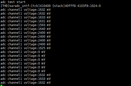
Change the input voltage of the pin and the detection value will change accordingly.
PWM API
Header File
ql_pwm.h, the header file of PWM API, is in ql_components/qadpt/include/ directory. Unless otherwise specified, all header files mentioned in this document are in this directory.
API Description
ql_pwmInit
This function initializes PWM.
- Prototype
ql_pwm_errcode_e ql_pwmInit(ql_pwm_channel_e pwm, UINT32 period, UINT32 duty_cycle)
- Parameter
pwm:
[In] PWM channel. See ql_pwm_channel_e for details.
period:
[In] PWM period. Actual output frequency: F = 26 MHz / period.
duty_cycle:
[In] Duty cycle value of PWM. It is less than the period value.
- Return Value
Result code. See ql_pwm_errcode_e for details.
ql_pwm_channel_e
The enumeration of PWM channels. There are 6 PWM channels in total.
typedef enum
{
  QL_PWM_0,
  QL_PWM_1,
  QL_PWM_2,
  QL_PWM_3,
  QL_PWM_4,
  QL_PWM_5,
} ql_pwm_channel_e
- Member
| Member | Description |
|---|---|
| QL_PWM_0 | PWM 0 |
| QL_PWM_1 | PWM 1 |
| QL_PWM_2 | PWM 2 |
| QL_PWM_3 | PWM 3 |
| QL_PWM_4 | PWM 4 |
| QL_PWM_5 | PWM 5 |
ql_pwm_errcode_e
The enumeration of PWM result codes:
typedef enum
{
  QL_PWM_SUCCESS = 0,
  QL_PWM_EXECUTE_ERR,
  QL_PWM_INVALID_PARAM_ERR,
} ql_pwm_errcode_e
- Member
| Member | Description |
|---|---|
| QL_PWM_SUCCESS | Successful execution |
| QL_PWM_EXECUTE_ERR | Failed execution |
| QL_PWM_INVALID_PARAM_ERR | Invalid parameter |
ql_pwmInit_level
This function sets initial output level of PWM.
- Prototype
ql_pwm_errcode_e ql_pwmInit_level(ql_pwm_channel_e pwm, ql_pwm_init_level_e level)
- Parameter
pwm:
[In] PWM channel. See ql_pwm_channel_e for details.
level:
[In] Initial level of PWM. See ql_pwm_init_level_e for details.
- Return Value
Result code. See ql_pwm_errcode_e for details.
ql_pwm_init_level_e
The enumeration of initial levels of PWM:
typedef enum
{
  QL_PWM_INIT_LEVEL_LOW =0,
  QL_PWM_INIT_LEVEL_HIGH,
} ql_pwm_init_level_e
- Member
| Member | Description |
|---|---|
| QL_PWM_INIT_LEVEL_LOW | Low level |
| QL_PWM_INIT_LEVEL_HIGH | High level |
ql_pwm_enable
This function enables PWM output.
- Prototype
ql_pwm_errcode_e ql_pwm_enable(ql_pwm_channel_e pwm)
- Parameter
pwm:
[In] PWM channel. See ql_pwm_channel_e for details.
- Return Value
Result code. See ql_pwm_errcode_e for details.
ql_pwm_disable
This function disables PWM output.
- Prototype
ql_pwm_errcode_e ql_pwm_disable(ql_pwm_channel_e pwm)
- Parameter
pwm:
[In] PWM channel. See ql_pwm_channel_e for details.
- Return Value
Result code. See ql_pwm_errcode_e for details.
ql_pwm_update_param
This function updates the parameters of PWM configuration. The parameter takes effect in next PWM period after updating.
- Prototype
ql_pwm_errcode_e ql_pwm_update_param(ql_pwm_channel_e pwm, UINT32 period, UINT32 duty_cycle)
- Parameter
pwm:
[In] PWM channel. See ql_pwm_channel_e for details.
period:
[In] PWM period value. Actual output frequency: F = 26 MHz / period.
duty_cycle:
[In] PWM duty cycle value. It is less than the period value.
- Return Value
Result code. See ql_pwm_errcode_e for details.
PWM Development Process
This chapter explains how to use the above PWM API in applications and perform basic debugging. The following subsections take PWM 1 as an example.
PWM Operation
The example of how to operate the PWM is provided in the module SDK. The demo is in ql_pwm_demo.c file in the ql_application/quectel_demo directory. The descriptions of related functions are as follows:
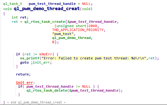
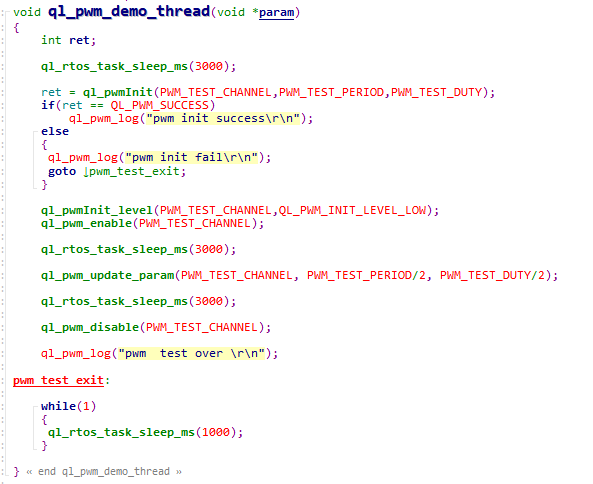
ql_pwm_demo_thread_creat(): This function creates a PWM task. You need to call the function to run PWM demo.ql_pwm_demo_thread(): This function executes a PWM task. It realizes the PWM output.
To run the example program, enable the CFG_ENABLE_QUECTEL_DEMO and CFG_ENABLE_QUECTEL_PWM macro definitions. This will automatically trigger the execution of ql_pwm_demo_thread_creat() and ql_pwm_demo_thread() to create a test task.
Function Debugging
You need to use the development board (Take FC41D TE-B as an example) with the module to debug the PWM function. Follow these steps for debugging:
Run the PWM demo as explained in PWM Operation. Enable the
QL_PWM_1macro definition to enable PWM 1.Recompile the firmware version and flash it to the module.
Reboot the module.
Get the pin waveforms of PWM 1 with logic analyzer.
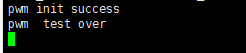
Open UART 2 to get the log information. The log information will be displayed as follows:
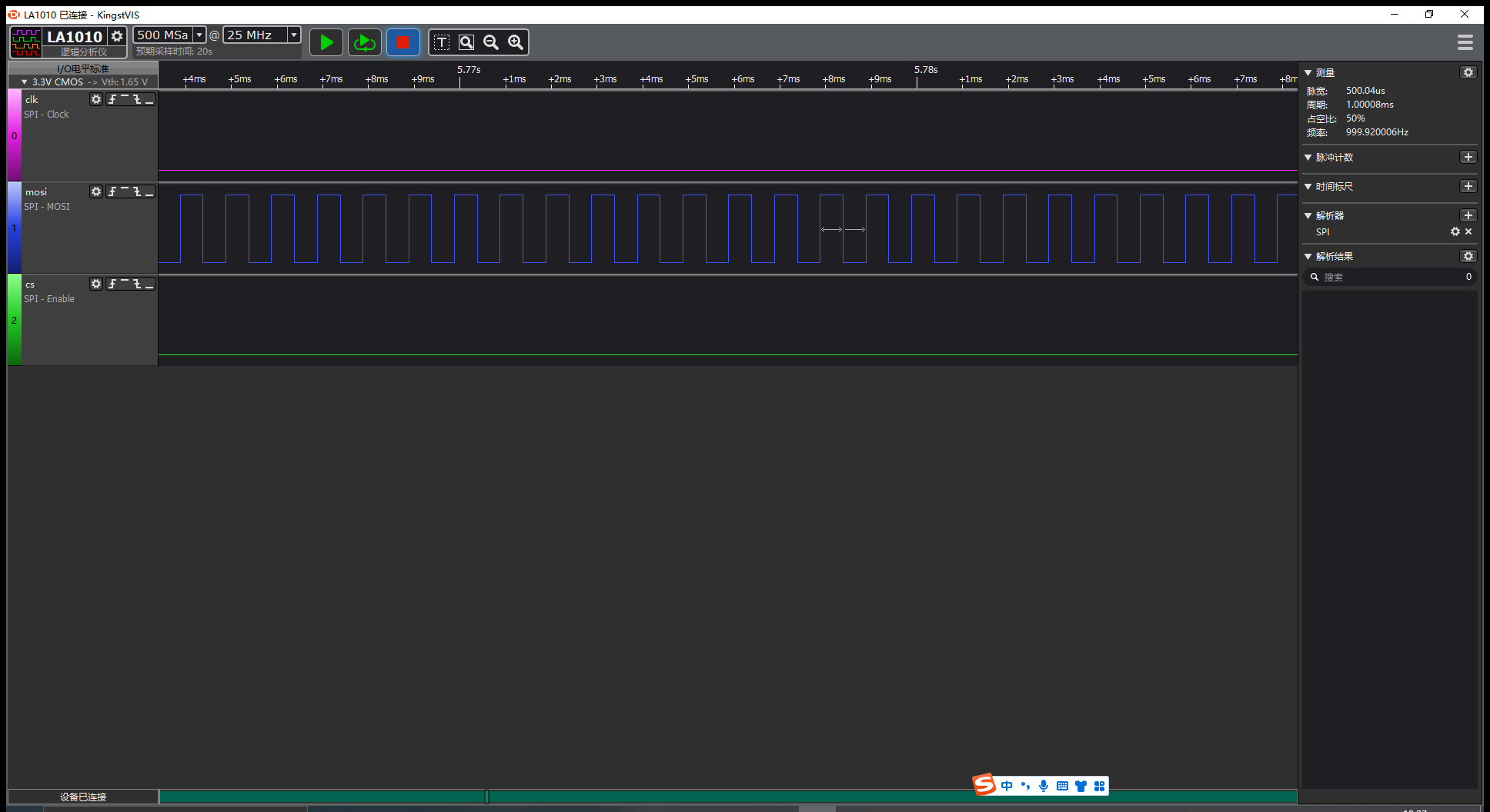
The waveform of PWM is the same as the configuration in the figure above. Therefore, it can be said that the PWM function test has passed.
Appendix References
Related Document
| Document Name |
|---|
| Quectel_FC41D&FCMxx0D&FLMx40D_QuecOpen(SDK)_Quick_Start_Guide |
Terms and Abbreviations
| Abbreviation | Description |
|---|---|
| ADC | Analog-to-Digital Converter |
| API | Application Programming Interface |
| CLK | Clock |
| CPHA | Clock Phase |
| CPOL | Clock Polarity |
| CTS | Clear To Send |
| DMA | Direct Memory Access |
| EEPROM | Electrically Erasable Programmable Read-Only Memory |
| FIFO | First in First Out |
| GPIO | General-Purpose Input/Output |
| I2C | Inter-Integrated Circuit |
| IoT | Internet of Things |
| LSB | Least Significant Bit |
| MSB | Most Significant Bit |
| PWM | Pulse Width Modulation |
| RTOS | Real-Time Operating System |
| RTS | Request To Send |
| SCK | Serial Clock |
| SDK | Software Development Kit |
| SPI | Universal Serial Bus |
| UART | Universal Asynchronous Receiver/Transmitter |
| VBAT | Voltage at Battery (Pin) |