

 English
General API Development Guide
Introduction
Quectel FC41D module, FCM100D module, FCM740D module and FLMx40D module supports QuecOpen® solution. QuecOpen® is an embedded development platform based on RTOS system. It is intended to simplify the design and development of IoT applications. For more information on QuecOpen®, see Quick_Start_Guide.
This document is applicable to QuecOpen® solution based on SDK build environment. This document provides an overview of the flash API, SPI flash API, timer API, watchdog API and low power mode API provided in the SDK of Quectel FC41D, FCM100D, FCM740D and FLMx40D modules, and the development procedures, as well as OTA API and OTA upgrade process in QuecOpen® solution.
Applicable Modules
Applicable Modules:
| Module Family | Module |
|---|---|
| - | FC41D |
| - | FCM100D |
| - | FCM740D |
| FLMx40D | FLM040D |
| FLM140D | |
| FLM240D | |
| FLM340D |
Flash
Header File
ql_flash.h, the header file of flash API, is in the ql_components/qadpt/include/ directory. Unless otherwise specified, all header files mentioned in this document are in this directory.
Flash API
ql_flash_set_security
This function sets the protection type of flash. You need to disable protection on the flash before writing data to it or erasing the data in it.
- Prototype
ql_errcode_flash_e ql_flash_set_security(ql_flash_protect_type_e type)
- Parameter
type:
[In] Protection type. See ql_flash_protect_type_e for details.
- Return Value
See ql_errcode_flash_e for result codes.
ql_flash_protect_type_e
The enumeration of the protection types of flash:
typedef enum
{
  QL_FLASH_PROTECT_NONE = 0,
  QL_FLASH_PROTECT_ALL,
  QL_FLASH_PROTECT_HALF,
  QL_FLASH_UNPROTECT_LAST_BLOCK,
} ql_flash_protect_type_e
- Member
| Member | Description |
|---|---|
QL_FLASH_PROTECT_NONE |
No protection |
QL_FLASH_PROTECT_ALL |
Protect whole flash |
QL_FLASH_PROTECT_HALF |
Protect half of flash |
QL_FLASH_UNPROTECT_LAST_BLOCK |
Protect flash except the last block |
ql_errcode_flash_e
The enumeration of result codes:
typedef enum
{
  QL_FLASH_SUCCESS = 0,
  QL_FLASH_EXECUTE_ERR,
  QL_FLASH_PARAM_ERROR,
} ql_errcode_flash_e
- Member
| Member | Description |
|---|---|
QL_FLASH_SUCCESS |
Successful execution |
QL_FLASH_EXECUTE_ERR |
Failed execution |
QL_FLASH_PARAM_ERROR |
Invalid parameter |
ql_flash_write
This function writes data to flash.
- Prototype
ql_errcode_flash_e ql_flash_write(unsigned char \*data, unsigned int addr, unsigned int len)
- Parameter
data:
[In] Data to be written.
addr:
[In] Address in flash where the data is to be written.
len:
[In] Length of data to be written. Unit: byte.
- Return Value
See ql_errcode_flash_e for result codes.
ql_flash_read
This function reads data from flash.
- Prototype
ql_errcode_flash_e ql_flash_read(unsigned char \*data, unsigned int addr, unsigned int len)
- Parameter
data:
[Out] Data content read from flash.
addr:
[In] Address where the data being read is stored.
len:
[In] Length of data. Unit: byte.
- Return Value
See ql_errcode_flash_e for result codes.
ql_flash_erase
This function erases data in flash. At least one sector (4 KB in size)
of data is erased at a time. The size of data erased each time is an integer multiple of the sector size.
- Prototype
ql_errcode_flash_e ql_flash_erase(unsigned int addr, unsigned int len)
- Parameter
addr:
[In] Address where the data to be erased is located.
len:
[In] Length of data to be erased. Unit: byte.
- Return Value
See ql_errcode_flash_e for result codes.
ql_flash_parttion_erase
This function erases data in specified partition in flash.
- Prototype
ql_errcode_flash_e ql_flash_parttion_erase(ql_partition_t inPartition, uint32_t off_set, uint32_t size)
- Parameter
inPartition:
[In] Partition where the data is to be erased. See *Chapter
2.2.5.1* for details.
off_set:
[In] The initial offset address of the data to be erased in partition.
size:
[In] Length of the data to be erased. Unit: byte.
- Return Value
See ql_errcode_flash_e for result codes.
ql_partition_t
The enumeration of flash partitions:
typedef enum
{
  QL_PARTITION_BOOTLOADER = 0,
  QL_PARTITION_APPLICATION,
  QL_PARTITION_OTA,
  QL_PARTITION_RF_FIRMWARE,
  QL_PARTITION_NET_PARAM,
  QL_PARTITION_USR_CONFIG,
  QL_PARTITION_BLE_BONDING_FLASH,
  QL_PARTITION_USR_RESERVE,
  QL_PARTITION_MAX,
} ql_partition_t
- Member
| Member | Description |
|---|---|
QL_PARTITION_BOOTLOADER |
Bootloader partition |
QL_PARTITION_APPLICATION |
App partition |
QL_PARTITION_OTA |
OTA partition |
QL_PARTITION_RF_FIRMWARE |
RF partition |
QL_PARTITION_NET_PARAM |
NET partition |
QL_PARTITION_BLE_BONDING_FLASH |
BLE partition |
QL_PARTITION_USR_RESERVE |
User configuration reserved partition |
QL_PARTITION_MAX |
Partition number in flash |
ql_flash_parttion_write
This function writes data to the specified partition in flash.
- Prototype
ql_errcode_flash_e ql_flash_parttion_write( ql_partition_t inPartition, volatile uint32_t off_set, uint8_t \*inBuffer , uint32_t inBufferLength)
- Parameter
inPartition:
[In] Partition where the data is to be written to. See *Chapter
2.2.5.1* for details.
off_set:
[In] The initial offset address of the data to be written in partition.
inBuffer:
[In] Data to be written.
inBufferLength:
[In] Length of data to be written. Unit: byte.
- Return Value
See ql_errcode_flash_e for result codes.
ql_flash_parttion_read
This function reads data in specified partition in flash.
- Prototype
ql_errcode_flash_e ql_flash_parttion_read( ql_partition_t inPartition, volatile uint32_t off_set, uint8_t \*outBuffer, uint32_t inBufferLength)
- Parameter
inPartition:
[In] Partition where the data is to be read. See ql_partition_t for details.
off_set:
[In] The initial offset address of the data to be read in partition.
outBuffer:
[In] Store the read data.
inBufferLength:
[In] Length of data to be read. Unit: byte.
- Return Value
See ql_errcode_flash_e for result codes.
Development Procedure
This chapter describes how to use above flash APIs in an application and perform basic feature debugging.
Operation Process
The example of how to operate flash is provided in SDK of the module. The demo is in ql_flash_demo.c under the ql_application/quectel_demo directory. The description of related functions:
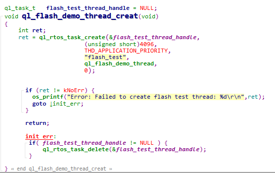
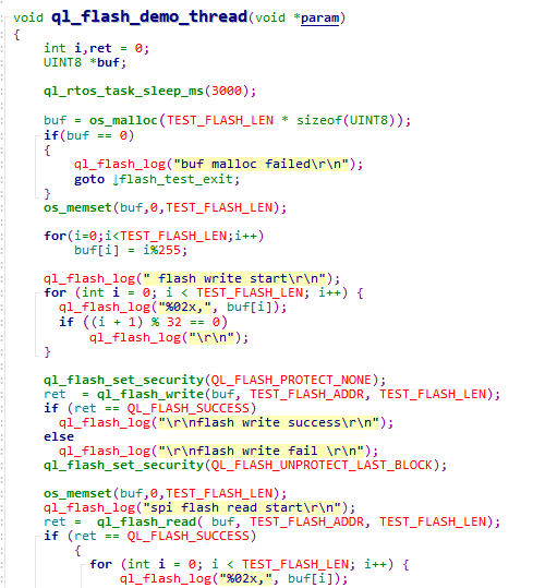
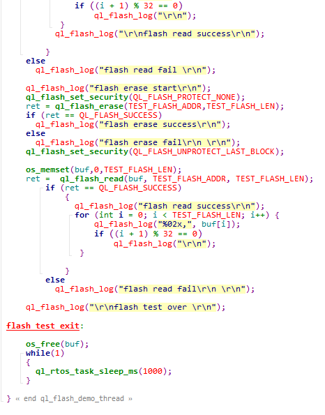
To run the demo, enable the macros CFG_ENABLE_QUECTEL_DEM and CFG_ENABLE_QUECTEL_FLASH first. Then ql_flash_demo_thread_creat() and ql_flash_demo_thread() will be called automatically to create a test task.
ql_flash_demo_thread_creat(): This function creates a flash task. You need to call the function to run the demo.ql_flash_demo_thread(): Task execution function, which writes data to flash, reads data from flash and erases data in flash.
Function Debugging
You need to use the TE-B of the module to debug the GPIO function. When debugging, run the Flash demo as described in Operation Process first, then recompile the firmware version, flash the new one to the module, and restart the module. Get log information through UART 2.
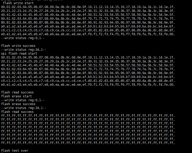
By examining the data in the figure above, it is clear that the operations involving writing data to flash, reading data from flash, and erasing data in flash have been carried out successfully.
SPI Flash
Header File
ql_spi_flash.h, the header file of SPI flash API, is in the ql_components/qadpt/include/ directory. Unless otherwise specified, all header files mentioned in this document are in this directory.
SPI Flash API
ql_spi_flash_read
This function reads flash directly without initializing SPI.
- Prototype
ql_errcode_spi_nor_e ql_spi_flash_read(unsigned char\* data, unsigned int addr, unsigned int len)
- Parameter
data:
[Out] Data to be read.
addr:
[In] Address where the data is to be read.
len:
[In] Length of read data. Unit: byte.
- Return Value
See ql_errcode_spi_nor_e for result codes.
ql_errcode_spi_nor_e
The enumeration of result codes:
typedef enum
{
  QL_SPI_FLASH_SUCCESS = 0,
  QL_SPI_FLASH_EXECUTE_ERR,
  QL_SPI_FLASH_PARAM_ERROR,
} ql_errcode_spi_nor_e
- Member
| Member | Description |
|---|---|
QL_SPI_FLASH_SUCCESS |
Successful execution |
QL_SPI_FLASH_EXECUTE_ERR |
Failed execution |
QL_SPI_FLASH_PARAM_ERROR |
Invalid parameter |
ql_spi_flash_write
This function writes data to flash directly without initializing SPI.
- Prototype
ql_errcode_spi_nor_e ql_spi_flash_write(unsigned char \*data, unsigned int addr, unsigned int len)
- Parameter
data:
[In] Data to be written to flash.
addr:
[In] Address where data is to be written.
len:
[In] Length of data to be written to flash. Unit: byte.
- Return Value
See ql_errcode_spi_nor_e for result codes.
ql_spi_flash_erase_chip
This function erases the full chip of flash.
- Prototype
ql_errcode_spi_nor_e ql_spi_flash_erase_chip(void)
- Parameter
None
- Return Value
See ql_errcode_spi_nor_e for result codes.
ql_spi_flash_erase_sector
This function erases a specified sector (size: 4 KB) data in flash.
- Prototype
ql_errcode_spi_nor_e ql_spi_flash_erase_sector(unsigned int addr)
- Parameter
addr:
[In] Specified sector address where the data is to be erased.
- Return Value
See ql_errcode_spi_nor_e for result codes.
ql_spi_flash_erase_64k_block
This function erases a specified block (size: 64 KB) of the flash.
- Prototype
ql_errcode_spi_nor_e ql_spi_flash_erase_64k_block(unsigned int addr)
- Parameter
addr:
[In] Specified block address where the data is to be erased.
- Return Value
See ql_errcode_spi_nor_e for result codes.
Development Procedure
This chapter describes how to use above SPI flash APIs in an application and perform basic feature debugging.
Operation Process
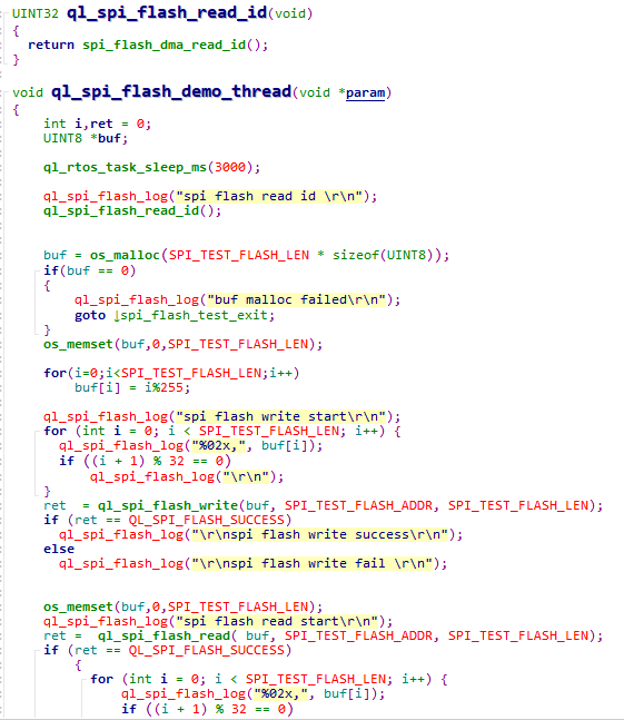
The example of how to operate SPI Flash is provided in SDK of the module. The demo is in ql_spi_flash_demo.c under the ql_application/quectel_demo directory. The description of related functions:
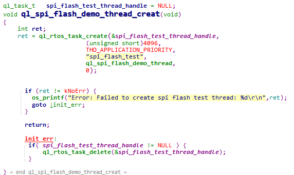
To run the demo, open the macros CFG_ENABLE_QUECTEL_DEMO, CFG_ENABLE_QUECTEL_SPI_FLASH and CFG_SUPPORT_SPI_FLASH_TEST first. Then ql_spi_flash_demo_thread_creat() and ql_spi_flash_demo_thread() will be called automatically to create a test task.
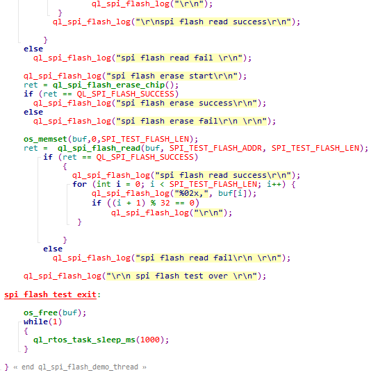
ql_spi_flash_demo_thread_creat(): This function creates a SPI Flash task. You need to call the function to run the demo.ql_spi_flash_demo_thread(): Task execution function, which writes data to flash, reads data from flash and erases data in flash through SPI. The flash model used in the example program is FM25W32.
Function Debugging
You need to use the TE-B of the module to debug the SPI Flash function. When debugging, run the SPI flash demo as described in Operation Process first, then recompile the firmware version, flash the new one to the module, and restart the module. Get log information through UART 2.
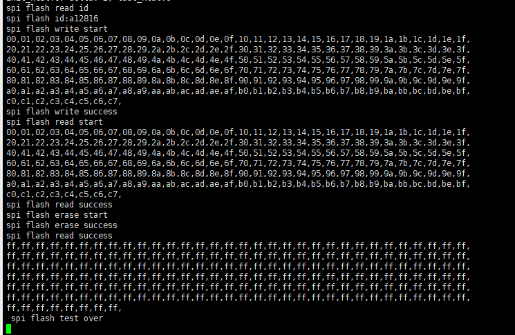
By examining the data, it is clear that that the operations involving writing data to flash, reading data from flash and erasing data in flash through SPI have been carried out successfully.
OTA Upgrade
Environment Preparation
Hardware Environment
Hardware: Quectel module (taking FC41D module as an example).
Firmware Flashing
Contact Quectel Technical Support to obtain BKFIL tool and related usage information.
Open BKFIL tool, then click "Select Port" on the main interface and choose the main port to flash the firmware.
Click the
 icon after "Bin Path" and choose the file
 ql_out/all_2M.1220.bin.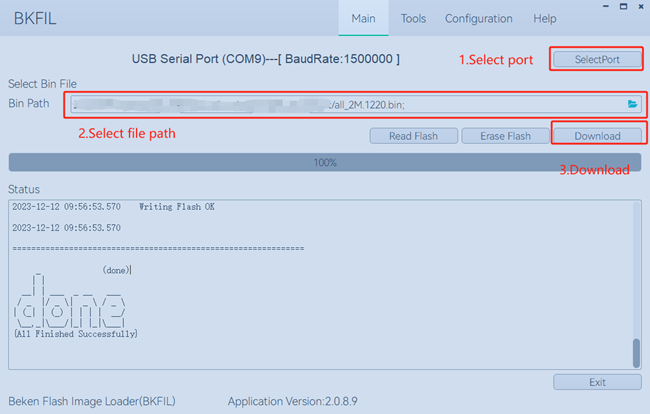
Click "Download" in the figure above, then press reset button on the module to flash the firmware.
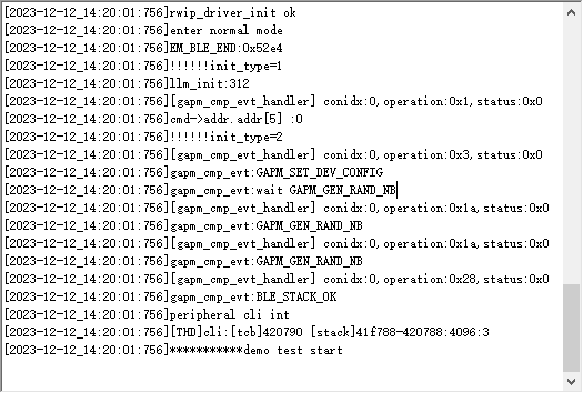
After flashing, if "done" is displayed in "Status" box, flashing is successful. Then reboot the module, select the module COM port to connect the module via serial port tool.
The boot log of the module is shown below:
OTA Upgrade Process
OTA Upgrade Package Generation
The steps to make an OTA upgrade package are shown below:
Copy the compilation file
FC41D.binunderql_outdirectory toql_tools/rtt_otdirectory.Contact Quectel Technical Support to obtain the rt_ota_packaging_tool_cli tool and copy it to the
ql_tools/rtt_otadirectory (for more information on the tool usage, please contact Quectel Technical Support).Use rt_ota_packaging_tool_cli tool to execute the following command to package the
FC41D.binfile as an OTA upgrade package. The default name of the generated upgrade package isFC41D.rbl
./rt_ota_packaging_tool_cli -f FC41D.bin -v 1.1.1 -p app -c gzip -s aes -i 0123456789ABCDEF -k 0123456789ABCDEF0123456789ABCDEF
OTA Upgrade Steps
OTA upgrade steps are shown below:
Please contact Quectel Technical Support to obtain HTTP File Server (HFS) tool to upgrade the firmware, which is stored in the LAN device .
Double-click the
HFS.exeto open the HTTP File Server (HFS) tool. After opening the tool, it automatically obtains the local LAN address and sets the HTTP service port to 80 by default, as shown in the following figure.Right click on "Add files..." in the left blank and choose the upgrade firmware package
FC41D.rbl. At this point the URL address for downloading the upgrade firmware package from HTTP server is http://192.168.94.41/FC41D.rbl.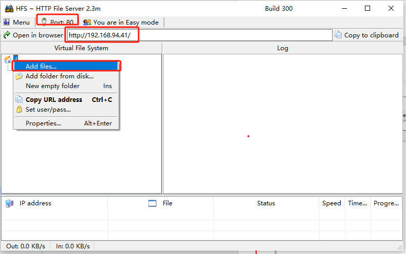
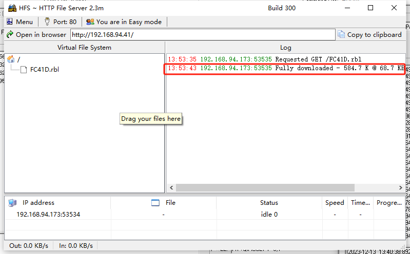
Execute the command below to establish a connection with the AP (make sure that the AP and the upgrade server are connected to the same LAN):
sta ssid 12345678Execute the command below on the terminal to perform the OTA upgrade:
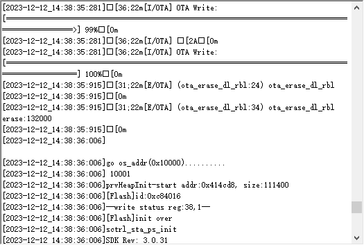
# http_ota <http://192.168.94.41/FC41D.rbl> (server address)If the upgrade succeeds, the interface will be:
OTA API
http_ota_download
This function downloads the firmware form HTTP server to upgrade the system.
- Prototype
Int http_ota_download(const char \*uri,int port)
- Parameter
uri:
[In] Remote HTTP server address.
port:
[In] The port number of the remote HTTP server.
- Return Value
0 Successful upgrade.
-1 Upgrade Failure.
Timer
The modules feature 6 timers, where timers 0, 1, and 2 operate with a clock source of 26 MHz, and timers 3, 4, and 5 utilize a clock source of 32 kHz. Timer 2 is used as the system time compensation timer, and timer 3 is used as the system time base timer. The modules support timers 0, 1, 4, and 5, while does not support timers 2 and 3.
Header File
ql_timer.h, the header file of timer API, is in the ql_components/qadpt/include/ directory. Unless otherwise specified, all header files mentioned in this document are in this directory.
Timer API
ql_TimerInit
This function initializes the timer. The unit of timing: millisecond.
- Prototype
ql_timer_errcode_e ql_TimerInit(ql_timer_number_e timer_id, UINT32 time_ms, ql_timer_callback timer_cb)
- Parameter
timer_id:
[In] Timer ID. See ql_timer_number_e for details.
time_ms:
[In] Timing duration. Unit: millisecond.
timer_cb:
[In] Callback function for timer interruption. See ql_timer_callback for details.
- Return Value
See ql_timer_errcode_e for result codes.
ql_timer_number_e
The enumeration of timer IDs:
typedef enum
{
  QL_TIMER_0 =0,
  QL_TIMER_1,
  QL_TIMER_2,
  QL_TIMER_3,
  QL_TIMER_4,
  QL_TIMER_5,
} ql_timer_number_e
- Member
| Member | Description |
|---|---|
QL_TIMER_0 |
Timer 0 |
QL_TIMER_1 |
Timer 1 |
QL_TIMER_2 |
Timer 2 |
QL_TIMER_3 |
Timer 3 |
QL_TIMER_4 |
Timer 4 |
QL_TIMER_5 |
Timer 5 |
ql_timer_errcode_e
The enumeration of result codes:
typedef enum
{
  QL_TIMER_SUCCESS = 0,
  QL_TIMER_EXECUTE_ERR,
  QL_TIMER_INVALID_PARAM_ERR,
  QL_TIMER_NOT_OPEN_ERR,
} ql_timer_errcode_e
- Member
| Member | Description |
|---|---|
QL_TIMER_SUCCESS |
Successful execution |
QL_TIMER_EXECUTE_ERR |
Failed execution |
QL_TIMER_INVALID_PARAM_ERRR |
Invalid parameter |
QL_TIMER_NOT_OPEN_ERR |
Timer is not enabled |
ql_TimerInit_us
This function initializes the timer. It is only supported by timers 0, 1 and 2.
- Prototype
ql_timer_errcode_e ql_TimerInit_us(ql_timer_number_e timer_id, UINT32 time_us, ql_timer_callback timer_cb)
- Parameter
timer_id:
[In] Timer ID. See ql_timer_number_e for details.
time_us:
[In] Timing duration. Unit: microsecond.
timer_cb:
[In] Callback function for timer interruption. See ql_timer_callback for details.
- Return Value
See ql_timer_errcode_e for result codes.
ql_get_timer_cnt
This function gets the timer count value.
- Prototype
ql_timer_errcode_e ql_get_timer_cnt(ql_timer_number_e timer_id, UINT32 *cont)
- Parameter
timer_id:
[In] Timer ID. See ql_timer_number_e for details.
cont:
[In] Pointer to the count value.
- Return Value
See ql_timer_errcode_e for result codes.
ql_TimerStart
This function starts the timer.
- Prototype
ql_timer_errcode_e ql_TimerStart(ql_timer_number_e timer_id)
- Parameter
timer_id:
[In] Timer ID. See ql_timer_number_e for details.
- Return Value
See ql_timer_errcode_e for result codes.
ql_TimerStop
This function stops the timer.
- Prototype
ql_timer_errcode_e ql_TimerStop(ql_timer_number_e timer_id)
- Parameter
timer_id:
[In] Timer ID. See ql_timer_number_e for details.
- Return Value
See ql_timer_errcode_e for result codes.
ql_timer_callback
This is the callback function for timer interruption.
- Prototype
typedef void (\*ql_timer_callback)(UINT8 arg)
- Parameter
arg:
[In] Inputted parameter.
- Return Value
None
Development Procedure
This chapter describes how to use above timer APIs in an application and perform basic feature debugging. Timer 5 is tested by default in this example.
Operation Process
The example of how to operate the timer is provided in SDK of the module. The demo is in ql_timer_demo.c under the ql_application/quectel_demo directory. The description of related functions:
To run the demo, open the macros CFG_ENABLE_QUECTEL_DEMO and CFG_ENABLE_QUECTEL_TIMER first. Then ql_timer_demo_thread_creat() and ql_timer_demo_thread() will be called automatically to create a test task.
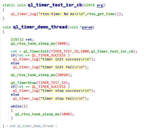
ql_timer_demo_thread_creat(): This function creates a timer task. You need to call the function to run the demo.ql_timer_demo_thread(): Task execution function. It can initialize the timer, executes the interrupt function and stops timing.
Function Debugging
You need to use the evaluation board of the module to debug the GPIO function. When debugging, run the timer demo as described in Operation Process first, then recompile the firmware version, flash the new one to the module, and restart the module. Get log information through the UART 2.
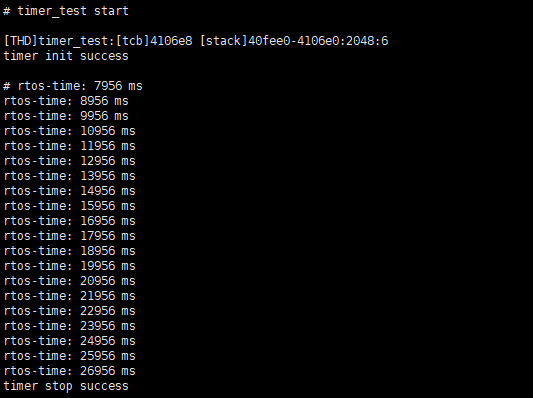
Print the system time for 20 times, and the timing interval is 1 second.
Watchdog
Header File
ql_watchdog.h, the header file of watchdog API, is in the ql_components/qadpt/include/ directory. Unless otherwise specified, all header files mentioned in this document are in this directory.
Watchdog API
ql_WdgInit
This function initializes the watchdog.
- Prototype
ql_wdg_errcode_e ql_WdgInit(UINT32 timeout)
- Parameter
timeout:
[In] Watchdog timeout. Unit: millisecond. Maximum value: 0xFFF (About 65 s).
- Return Value
See ql_wdg_errcode_e for result codes.
ql_wdg_errcode_e
The enumeration of result codes:
typedef enum
{
  QL_WDG_SUCCESS = 0,
  QL_WDG_EXECUTE_ERR,
  QL_WDG_INVALID_PARAM_ERR,
} ql_wdg_errcode_e
- Member
| Member | Description |
|---|---|
QL_WDG_SUCCESS |
Successful execution |
QL_WDG_EXECUTE_ERR |
Failed execution |
QL_WDG_INVALID_PARAM_ERR |
Invalid parameter |
ql_wdg_reload
This function feeds the watchdog.
- Prototype
void ql_wdg_reload(void)
- Parameter
None
- Return Value
None
ql_wdg_finalize
This function closes the watchdog.
- Prototype
void ql_wdg_finalize(void)
- Parameter
None
- Return Value
None
Example
The example of how to operate the watchdog API is provided in SDK of the module. The demo is in ql_watchdog_demo.c file under the ql_application/quectel_demo directory. The description of related functions:
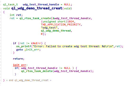
ql_wdg_demo_thread_creat(): This function creates watchdog tasks. You need to call the function to run the demo.ql_wdg_demo_thread(): This is the execution function of the task. It can initialize and feed the watchdog.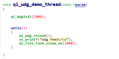
Low Power Mode
Header File
ql_lowpower_demo.h, the header file of low power mode API, is in the ql_components/qadpt/include/ directory. Unless otherwise specified, all header files mentioned in this document are in this directory.
Low Power Mode API
ql_deep_sleep_enter
This function allows MCU to enter the deep sleep mode.
- Prototype
ql_lowpower_errcode_e ql_deep_sleep_enter(ql_sleep_ctrl_parm_s deep_sleep_param)
- Parameter
deep_sleep_param:
[In] Corresponding configuration of the deep sleep mode. See ql_sleep_ctrl_parm_s for details.
- Return Value
See ql_lowpower_errcode_e for result codes.
ql_lowpower_errcode_e
The enumeration of result codes:
typedef enum
{
  QL_LOWPOWER_SUCCESS = 0,
  QL_LOWPOWER_EXECUTE_ERR,
  QL_LOWPOWER_INVALID_PARAM_ERR,
} ql_lowpower_errcode_e
- Member
| Member | Description |
|---|---|
QL_LOWPOWER_SUCCESS |
Successful execution |
QL_LOWPOWER_EXECUTE_ERR |
Failed execution |
QL_LOWPOWER_INVALID_PARAM_ERR |
Invalid parameter |
ql_sleep_ctrl_parm_s
The structure of corresponding configuration of the deep sleep mode and low voltage standby mode:
typedef struct ql_ps_sleep_ctrl
{
  ql_deep_wakeup_way wake_up_way;
  UINT32 gpio_index_map;
  UINT32 gpio_edge_map;
  UINT32 gpio_stay_lo_map;
  UINT32 gpio_last_index_map;
  UINT32 gpio_last_edge_map;
  UINT32 gpio_stay_hi_map;
  UINT32 sleep_time;
  UINT32 lpo_32k_src;
} ql_sleep_ctrl_parm_s
- Parameter
| Type | Parameter | Description |
|---|---|---|
| ql_deep_wakeup_way | wake_up_way | Methods for waking up MCU. See Chapter 7.2.1.2.1 for details. |
| UINT32 | gpio_index_map | Pins for waking up MCU. GPIO 0--GPIO 31. The bits of the GPIO register correspond with the pins one to one in order. |
| UINT32 | gpio_edge_map | Edges for waking up MCU. GPIO 0--GPIO 31. The bits of the GPIO register correspond with the pins one to one in order. 0 Rising edge; 1 Falling edge |
| UINT32 | gpio_stay_lo_map | Whether pins need to remain in the original status when MCU is in the deep sleep mode. GPIO 0--GPIO 31. The bits of the GPIO register correspond with the pins one to one in order. 0 No; 1 Yes |
| UINT32 | gpio_last_index_map | Pins for waking up MCU (no configuration required). |
| UINT32 | gpio_last_edge_map | Edges for waking up MCU (no configuration required). |
| UINT32 | gpio_stay_hi_map | Whether pins need to remain in the original status when MCU is in the deep sleep mode (no configuration required). |
| UINT32 | sleep_time | Sleep time. This parameter is valid when the method for waking up MCU is RTC timing wake-up. Unit: second. |
| UINT32 | lpo_32k_src | RTC clock source (no configuration required). |
ql_lowvol_sleep_enter
This function allows MCU to enter the low voltage standby mode.
- Prototype
ql_lowpower_errcode_e ql_lowvol_sleep_enter(ql_sleep_ctrl_parm_s lowvol_sleep_param)
- Parameter
lowvol_sleep_param:
[In] Corresponding configuration of the low voltage standby mode. See ql_sleep_ctrl_parm_s for details.
- Return Value
See ql_lowpower_errcode_e for result codes.
ql_deep_mcudtim_enter
This function allows MCU to enter or exit the normal standby mode.
- Prototype
ql_lowpower_errcode_e ql_deep_mcudtim_enter(UINT32 enable, UINT32 dtimnum)
- Parameter
enable:
[In] Enter or exit the normal standby mode.
0 Exit
1 Enter
dtimnum:
[In] Whether MCU enters the Wi-Fi keep alive mode in the normal standby mode.
0 No
Others Time intervals of waking up MCU in the Wi-Fi keep alive mode. Unit: 100 ms (it is recommended to set the value as 30, that is, 3000 ms).
- Return Value
See ql_lowpower_errcode_e for result codes.
ql_deep_rfdtim_enter
This function enables or disables RF sleep mode.
- Prototype
ql_lowpower_errcode_e ql_deep_rfdtim_enter(UINT32 enable,UINT32 arpenable)
- Parameter
enable:
[In] Enable or disable RF sleep mode.
0 Disable
1 Enable
arpenable:
[In] Whether to enable the ARP broadcast for waking up MCU after MCU enters Wi-Fi keep alive mode in the normal standby mode.
0 Disable
1 Enable. Enabling the ARP broadcast will increase the power consumption and reduce the rate of losing packets.
- Return Value
See ql_lowpower_errcode_e for result codes.
ql_set_gpio_wakeup_index
This function sets GPIO pins for waking up MCU in the Wi-Fi keep alive mode (wakes up MCU by rising edge).
- Prototype
ql_lowpower_errcode_e ql_set_gpio_wakeup_index(UINT8 gpio)
- Parameter
gpio:
[In] GPIO pins for waking up MCU.
- Return Value
See ql_lowpower_errcode_e for result codes.
ql_ps_clear_gpio
This function clears the GPIO status for waking up MCU to allow MCU to enter the Wi-Fi keep alive mode again.
- Prototype
ql_lowpower_errcode_e ql_ps_clear_gpio(void)
- Parameter
None
- Return Value
See ql_lowpower_errcode_e for result codes.
Development Procedure
This chapter describes how to use above low power mode APIs in an application and perform basic feature debugging. The Wi-Fi keep alive mode is tested by default in this example.
Operation Process
The example of how to operate the low power mode API is provided in SDK of the module. The demo is in ql_lowpower_demo.c file under the ql_application/quectel_demo directory. The description of related functions:
To run the demo, open the macros CFG_ENABLE_QUECTEL_DEMO and CFG_ENABLE_QUECTEL_LOWPOWER first, then ql_lowpower_demo_thread_creat() and ql_lowpower_demo_thread() are called automatically to create a test task.
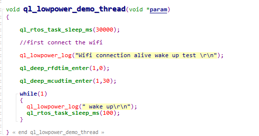
ql_lowpower_demo_thread_creat(): This function creates a low power task. You need to call the function to run the demo.ql_lowpower_demo_thread(): Task execution function, which allows MCU to enter the Wi-Fi keep alive mode.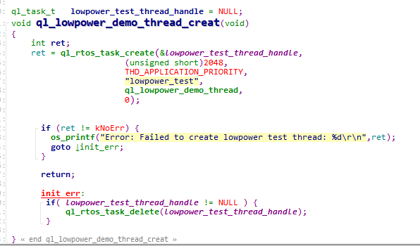
Function Debugging
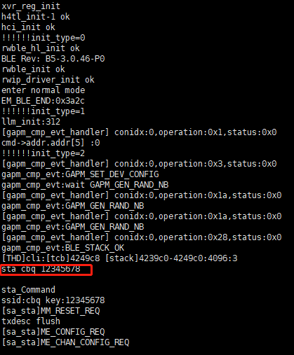
You need to use the evaluation board of the module to debug the GPIO function. When debugging, run the low power demo as described in Operation Process first, then recompile the firmware version, flash the new one to the module, and finally restart the module. Reset logs can be obtained through UART 2. Then send STA command (STA SSID Key) to connect Wi-Fi, otherwise MCU cannot enter the Wi-Fi keep alive mode.
After Wi-Fi is connected, you need to wait for a while before MCU enters the Wi-Fi keep alive mode.
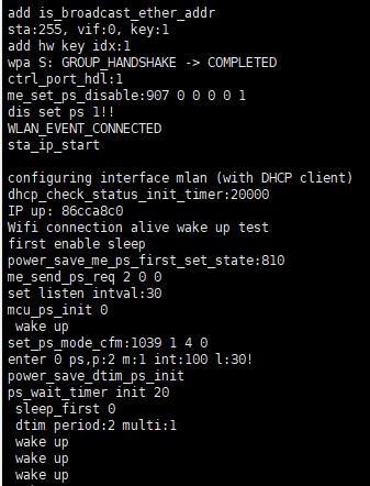
After MCU enters the Wi-Fi keep alive mode, Wi-Fi is still connected. The serial port tool will print "wake up" after MCU is woken up by RTC timer.
Appendix References
Related Document
| Document Name |
|---|
| Quectel_FC41D&FCM100D&FCM740D&FLMx40D_QuecOpen(SDK)_Quick_Start_Guide |
Terms and Abbreviations
| Abbreviation | Description |
|---|---|
| AP | Access Point |
| API | Application Programming Interface |
| ARP | Address Resolution Protocol |
| GPIO | General-Purpose Input/Output |
| HTTP | Hyper Text Transfer Protocol |
| IoT | Internet of Things |
| MCU | Microprogrammed Control Unit |
| OTA | Over-the-Air Technology |
| RF | Radio Frequency |
| RTC | Real-Time Clock |
| RTOS | Real-Time Operating System |
| SSID | Service Set Identifier |
| STA | Station |
| SDK | Software Development Kit |
| SPI | Serial Peripheral Interface |