
BG95 EVB Introduction
Supported Module List
Feature List
Overview
The QuecPython_BG95_EVB is a compact and portable "pocket-sized" EVB specifically designed for QuecPython.
The main board is equipped with a BG95 series module and a Type-C interface. You can easily develop the EVB with just a USB Type-C cable.
The EVB is also equipped with an expansion board that supports light sensors, UV sensors, VOC sensors, nine-axis sensors, and temperature and humidity sensors.
The EVB is compatible with Raspberry Pi Zero, and the expansion board for Raspberry Pi Zero can be directly used on the QuecPython_BG95_EVB.
Description
The main components and interface layout of the EVB are shown in the following figure.

Resource Download
EVB Resources
EVB Interface
8 Pin Assignment
| Pin Header | Number | Silkscreen | Pin No. | Function |
|---|---|---|---|---|
| JP6 | 1 | PWK_AUTO | 15 | POWERKEY |
| JP6 | 2 | PWK_AUTO | - | GND |
| JP6 | 3 | VDD_EXT | - | 1.8 V |
| JP6 | 4 | VDD_EXT | 29 | VDD_EXT |
| JP6 | 5 | MODULE_EN | - | 3.6 V |
| JP6 | 6 | MODULE_EN | - | 3.6 V |
| JP6 | 7 | GNSS_EN | - | 3.3 V |
| JP6 | 8 | GNSS_EN | 51 | GNSS_EN |
- 1 & 2: Automatic power-on.
- 3 & 4: connect VDD_EXT to provide power for external circuit. For power consumption measurement, VDD_EXT needs to be disconnected.
- 5 & 6: Turn on the DC-DC converter to provide power to the module.
- 7 & 8: Enable active power supply for GNSS.
40 Pin Assignment
| Pin Header | Number | Name | GPIO Multiplexing | Function | Pin Header | Number | Name | GPIO Multiplexing | Function |
|---|---|---|---|---|---|---|---|---|---|
| JP7 | 1 | 3V3 | - | 3.3 V Output | JP8 | 2 | 5V | - | 5 V Output |
| JP7 | 3 | SDA1 | I2C1_SDA GPIO14 |
I2C1 Data General Purpose Input/Output |
JP8 | 4 | 5V | - | 5 V Output |
| JP7 | 5 | SCL1 | I2C1_SCL GPIO13 |
I2C1 Clock General Purpose Input/Output |
JP8 | 6 | GND | - | Ground |
| JP7 | 7 | P35 | GPIOX UART4_TXD |
General Purpose Input/Output UART4 Send |
JP8 | 8 | TX2 | UART2_TXD | UART2 Send |
| JP7 | 9 | GND | - | Ground | JP8 | 10 | RX2 | UART2_RXD | UART2 Recv |
| JP7 | 11 | P06 | GPIO3 PCM_DIN |
General Purpose Input/Output Digital Audio Input signal |
JP8 | 12 | P37 | GPIOX I2C_SDA |
General Purpose Input/Output I2C Data |
| JP7 | 13 | P05 | GPIO2 PCM_SYNC |
General Purpose Input/Output Digital Audio Sync signal |
JP8 | 14 | GND | - | Ground |
| JP7 | 15 | P04 | GPIO1 PCM_CLK |
General Purpose Input/Output Digital Audio Clock signal |
JP8 | 16 | P86 | GPIO19 | General Purpose Input/Output |
| JP7 | 17 | 3V3 | - | 3.3V Output | JP8 | 18 | P88 | GPIO21 | General Purpose Input/Output |
| JP7 | 19 | MO2 | SPI2_MOSI GPIO8 UART0_TXD |
SPI2 Master Output Slave Input General Purpose Input/Output UART0 Send |
JP8 | 20 | GND | - | Ground |
| JP7 | 21 | MI2 | SPI2_MISO GPIO7 UART0_RXD |
SPI2 Master Input Slave Output General Purpose Input/Output UART0 Recv |
JP8 | 22 | P20 | GPIOX | General Purpose Input/Output |
| JP7 | 23 | CLK2 | SPI2-CLK GPIO5 I2C0_CLK |
SPI2 Clock General Purpose Input/Output I2C0 Clock |
JP8 | 24 | CS2 | SPI2_CS GPIO6 I2C0_SDA |
SPI2 Chip Select General Purpose Input/Output I2C0 Data |
| JP7 | 25 | GND | - | Ground | JP8 | 26 | P38 | GPIOX | General Purpose Input/Output |
| JP7 | 27 | P25 | GPIO9 SPI0_CS |
General Purpose Input/Output SPI0 Chip Select |
JP8 | 28 | P26 | GPIO10 SPI0_CLK |
General Purpose Input/Output SPI0 Clock |
| JP7 | 29 | P34 | GPIOX UART4_RXD |
General Purpose Input/Output UART4 Recv |
JP8 | 30 | GND | - | Ground |
| JP7 | 31 | P87 | GPIO20 | General Purpose Input/Output | JP8 | 32 | PWM | PWM0 GPIO17 |
PWM0 Output General Purpose Input/Output |
| JP7 | 33 | P85 | GPIO18 PWM1 |
General Purpose Input/Output PWM1 Output |
JP8 | 34 | GND | - | Ground |
| JP7 | 35 | P28 | GPIO12 SPI0_MISO UART3_RXD |
General Purpose Input/Output SPI0 Master Input Slave Output UART3 Recv |
JP8 | 36 | P39 | GPIOX | General Purpose Input/Output |
| JP7 | 37 | P07 | GPIO4 PCM_DOUT |
General Purpose Input/Output Digital Audio Output signal |
JP8 | 38 | P27 | GPIO11 SPI0_MOSI UART3_TXD |
General Purpose Input/Output SPI0 Master Output Slave Input UART3 Send |
| JP7 | 39 | GND | Ground | JP8 | 40 | P36 | GPIOX I2C_SCL |
General Purpose Input/Output I2C Clock |
The main pin layout of the EVB is shown in the figure below.

Note
For more information about QuecPython_BG95_EVB, please visit https://developer.quectel.com/en/resource-download?cid=5&pid=238.
EVB Configuration
The peripheral pin assignments are detailed as follows.
| No. | Name | Model | Supported | Silkscreen | Remarks |
|---|---|---|---|---|---|
| 1 | USB_TYPEC Interface | - | Yes | - | - |
| 2 | SIM Card Slot | SMN-315-ARP7 | Yes | CARD2 | Nano-SIM |
| 3 | LED Indicator (see below) | - | Yes | - | - |
On-board LED indicators:
- SIM_CHK: The SIM_CHK indicator lights up when a SIM card is inserted into the card slot.
- NET: Network indicator.
- PSM: Sleep mode indicator.
- PWM: PWM function indicator.
- PWR: Power indicator.
Refer to the silkscreen below the module in the EVB front figure (The module side) above for LED indicator locations.
Quick Start Guide
Hardware Preparation
Step 1: Required Items
- Development board
- USB-C cable (A-to-C)
- Windows 10 PC
- Nano-SIM card
- 4G antenna
Step 2: Antenna & SIM Installation
- Attach the provided antenna to the MAIN antenna port.
- Insert the SIM card into the Nano-SIM slot.
Step 3: Connect the Board
- Power the board via USB-C.
Step 4: Power On
- Press and hold PWK until the power indicator light on the mainboard (labeled as POW) lights up.
- If you short-circuited PWK_ON, there's no need to press PWK; the board will power on automatically.
If the PWR indicator is constantly on, the EVB is successfully turned on.
Driver Installation
- Download the QuecPython USB Driver from QuecPython Official Drivers.
- Extract and run
setup.exeorsetup.bat. - Verify installation in Device Manager (look for "Quectel USB" ports). Ignore unrelated devices like "Mobile ECM Network Adapter."
Tool Installation
- QPYcom: Download from QuecPython Tools. Extract and use directly.
- VSCode Plugin: Search for "QuecPython" in the Visual Studio Code marketplace.

Firmware Burning
Firmware Download: Get the latest QuecPython firmware for BG95 from QuecPython Firmware Page.
Burning Steps:
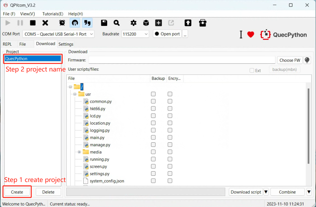
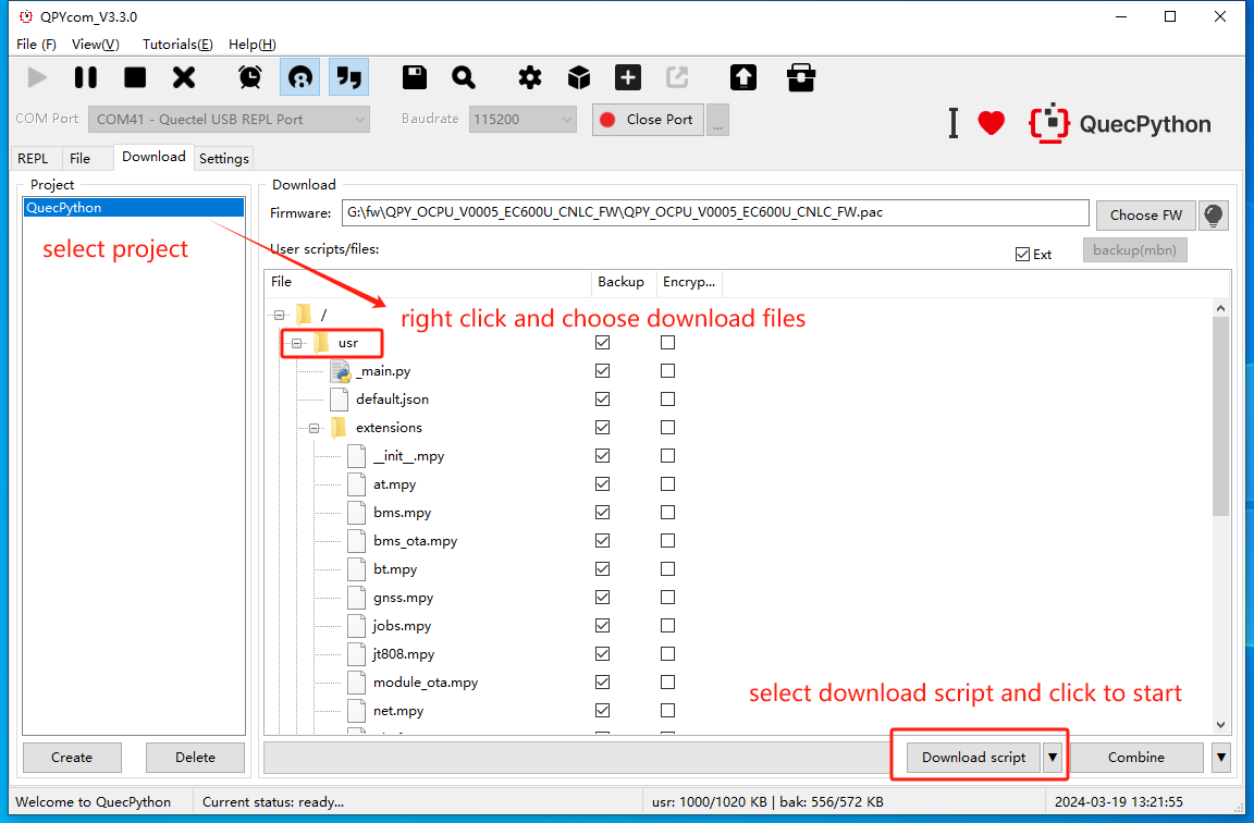
Open QPYcom, select the USB REPL port, and create a new project.
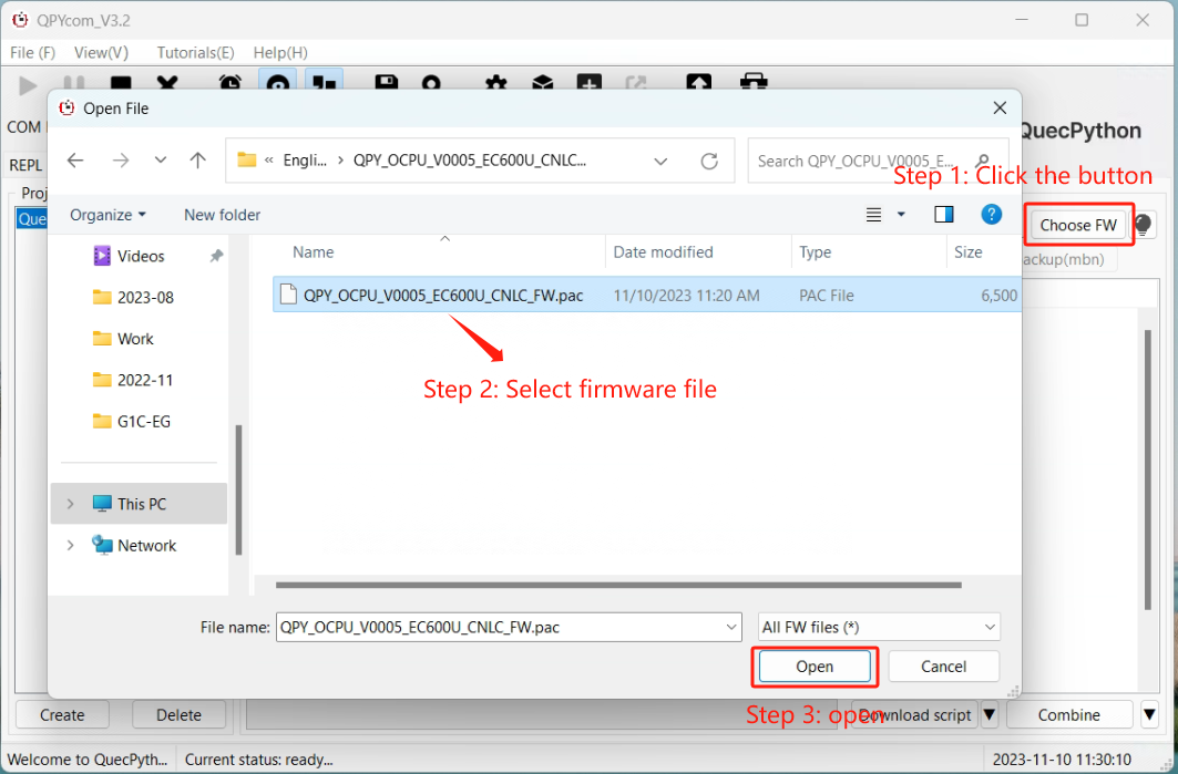
Choose the
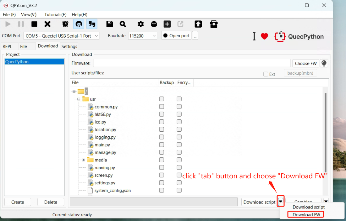
.binfirmware file (BG95 requires.mbnformat for older versions).Set mode to "Download FW" and click Download.
For BG95, enable DM serial port before burning.
REPL Debugging
- Connect via QPYcom and open the REPL interface.
- Test with
print("Hello World!").

First Script Development
Writing a Script
Create helloworld.py:
print("Hello World!")
File Transfer
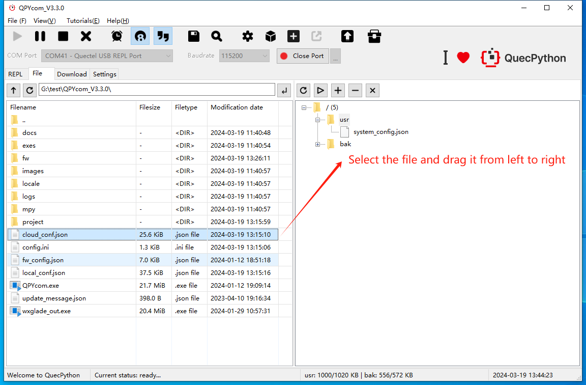
- Method 1: Drag-and-drop files via QPYcom’s GUI.
- Method 2: Use the "Download Script" feature in QPYcom.
Running Scripts
Execute via REPL:
import example
example.exec("/usr/helloworld.py")
Stopping Program Execution
How to stop a running program. The following methods are provided according to the type of the running script file:
| Is the program name main.py? | Does the program contain a dead loop? | Does the program use multiple threads? | Stopping Steps |
|---|---|---|---|
| ✓ | ✓ | ✓ | (1) Press Ctrl + A to enter RAW mode (2) Press Ctrl + D to restart the QuePython virtual machine (3) Press Ctrl + B to return to the normal interactive mode (4) If the above methods fail, re-flash the firmware |
| ✓ | ✓ | ✗ | (1) Press Ctrl + C to interrupt the program execution (2) If the above method fails, re-flash the firmware |
| ✓ | ✗ | ✓ | (1) Press Ctrl + A to enter RAW mode (2) Press Ctrl + D to restart the QuePython virtual machine (3) Press Ctrl + B to return to the normal interactive mode (4) If the above methods fail, wait for the program to finish running |
| ✓ | ✗ | ✗ | (1) Press Ctrl + C to interrupt the program execution (2) If the above method fails, re-flash the firmware |
| ✗ | ✓ | ✓ | (1) Press Ctrl + D to restart the QuePython virtual machine (2) If the above method fails, directly restart the module |
| ✗ | ✓ | ✗ | (1) Press Ctrl + D to restart the QuePython virtual machine (2) If the above method fails, directly restart the module |
| ✗ | ✗ | ✓ | (1) Press Ctrl + C to interrupt the program execution (2) If the above method fails, re-flash the firmware or directly restart the module |
| ✗ | ✗ | ✗ | (1) Press Ctrl + C to interrupt the program execution (2) If the above method fails, re-flash the firmware or directly restart the module |
Low Power Consumption Testing Guide
The BG95 module supports multiple operating modes, each with distinct power consumption characteristics. The common operating modes are as follows:
ACTIVE: The module is engaged in LTE data transmission, GSM calls, or executing RTOS logic. Power consumption varies significantly depending on specific tasks and network communication standards, as both CPU power usage and RF power levels differ across scenarios.
IDLE: The module is in an idle state with hardware fully powered and RTOS running, but no active threads. It resumes operation immediately upon task initiation or incoming network activity. ECX00U series modules reduce clock frequency in IDLE mode, entering a light sleep state (disabling high-speed clocks while keeping the CPU active).
Sleep: Sleep mode requires the module to be idle with autosleep enabled. In this mode, RTOS pauses, clock frequency slows, and peripheral controllers (UART, SPI, etc.) are powered down, retaining only essential interrupt controllers to minimize power consumption.
PSM: PSM (Power Saving Mode) is a 3GPP-defined low-power mode where the module periodically wakes to perform tasks and remains in PSM sleep otherwise. During PSM sleep, behavior and power consumption resemble a powered-off state.
Power Off: The module is fully powered down, with baseband chips and peripheral controllers disabled (PMIC remains active). It can be awakened via Powerkey or RTC alarm.
| Module Model | BG95 |
|---|---|
| IDLE (LTE FDD@64ms) | 18.9 mA (catm@128ms) |
| SLEEP (LTE FDD@64ms) | 1.89 mA (catm@128ms) |
| SLEEP (CFUN0) | 0.575 mA |
| PSM | 5.10 μA |
| Power Off | 14.87 μA |
Test Preparation
Step 1: Hardware Setup
Prepare the following components before starting:
- Development Board
- USB Cable (USB-A to USB-TypeC)
- PC (Windows 10)
- SIM Card
- 4G Antenna
- Power Monitor Mini
Step 2: Antenna & SIM Card Installation
Install the provided antenna into the MAIN antenna socket and insert the SIM card into the development board's SIM slot.
Step 3: Board Connection
Connect the development board's Type-C port to the PC using a USB Type-C cable. Attach the power monitor's positive lead to MODULE_EN's Vbat (refer to BG95 User Guide) and the negative lead to the module's GND. Connection diagram:
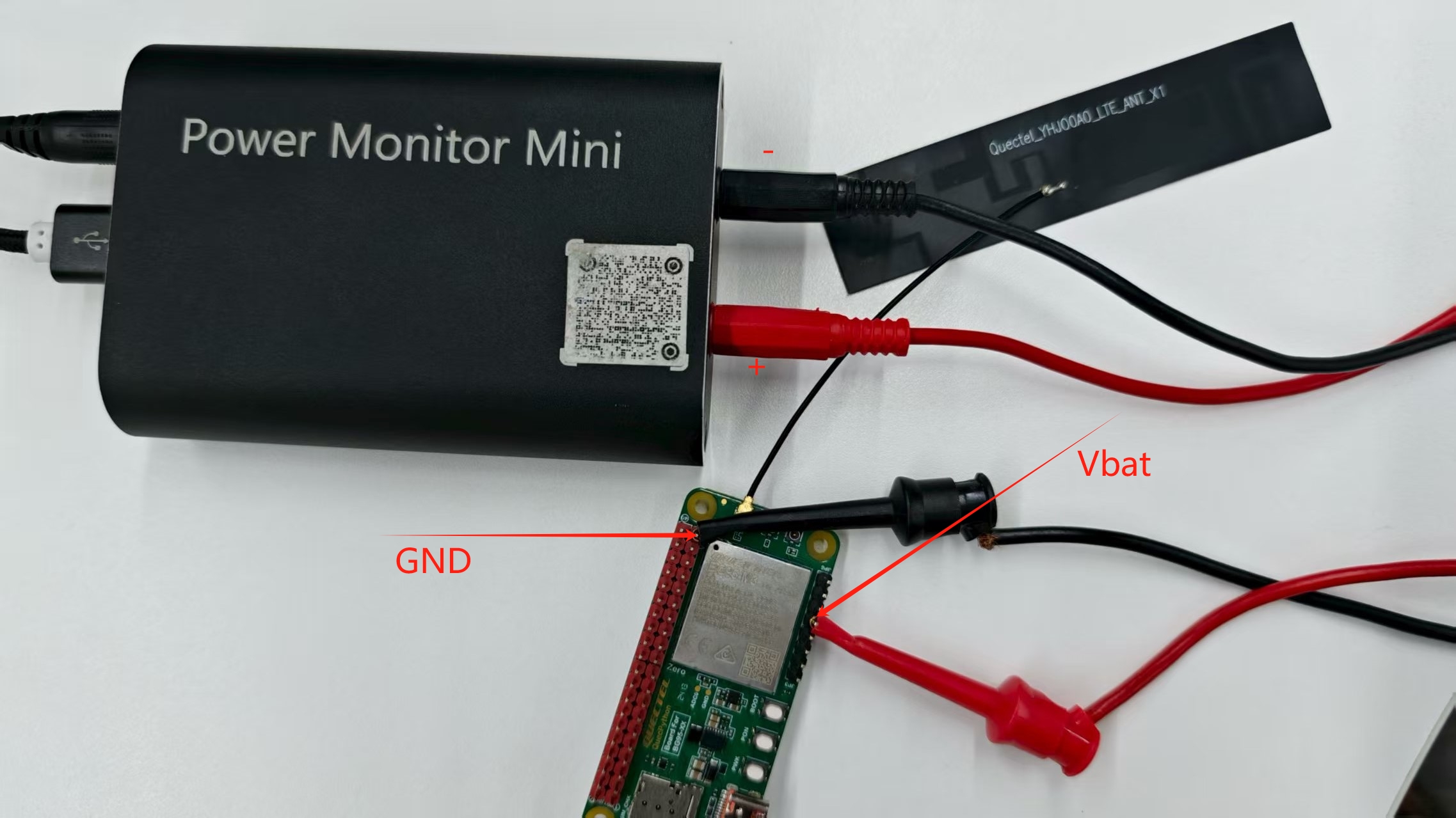
Important!
Remove all jumper caps during measurements to avoid external interference.
Power Consumption Measurement
Power-Off Current
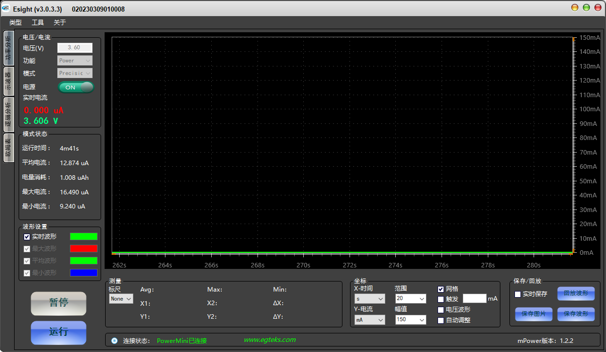
With the board connected via USB Type-C, power off the module by disabling USB_VBus (set USB switch to "off" on the board's rear). Measure the current while the module is inactive (output pins pulled low/floating). Average current remains stable at microampere levels.
Idle Current
After power-off measurement, press and hold Powerkey to boot the module (default: IDLE mode). The module remains idle with RTOS running but no active threads, ready to resume instantly for tasks or calls.
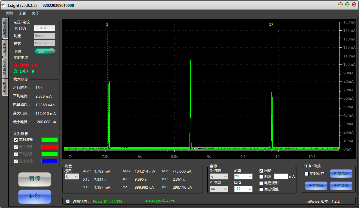
Sleep Current
With autosleep enabled during idle, the module enters sleep mode by deactivating non-essential IP cores (peripherals/interrupts) and reducing clock frequency.
Re-enable USB_VBus.
Open QPYcom Tool and execute:
import pm
pm.autosleep(1)  # Enable autosleep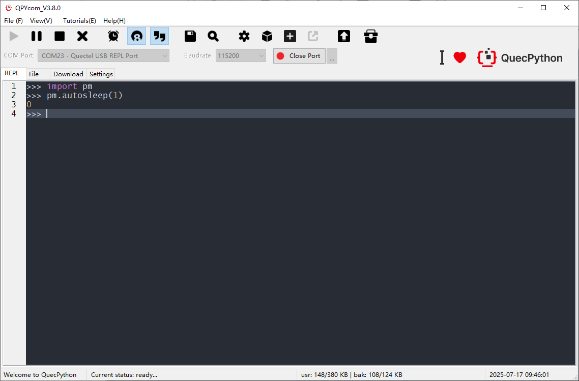
Disable USB_VBus again (switch to "off").
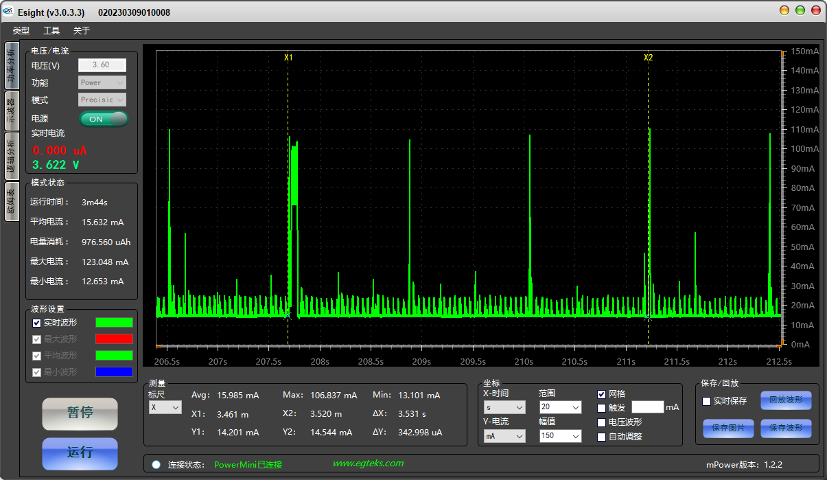
API Reference | DetailsSleep current shows periodic spikes:
PSM Current
To enable PSM:
- Request PSM from the base station (via ATTACH/TA_UPDATER with timer parameters).
- Note: Base station determines final timer values.
- Once ACT timer expires in IDLE, the module shuts down CPU/RF (partial power-off), retaining wake-up sources (ACT/TAU timers, PSM_INT).
Steps:
Enable USB_VBus.
-
pm.set_psm_time(tau_uint,tau_time,act_uint,act_time) # Configure PSM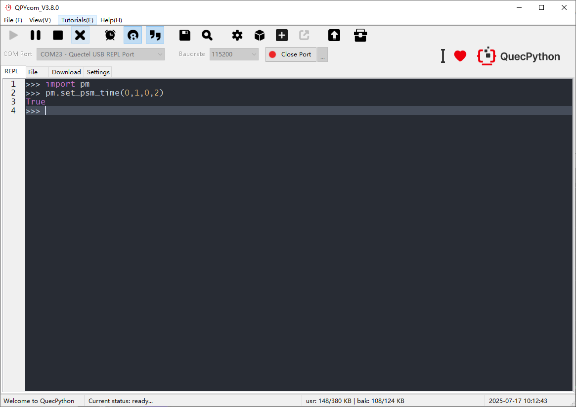
Disable USB_VBus.
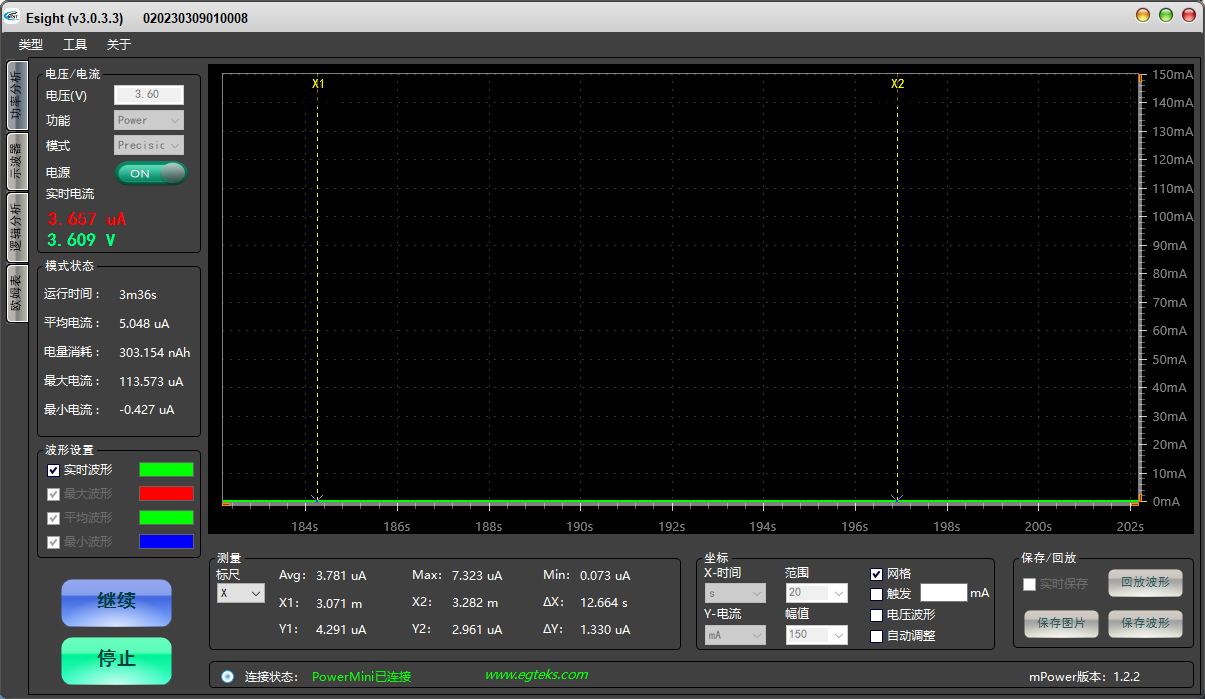
PSM baseline current (µA-level, similar to power-off):
Notes:
- Confirm carrier support for PSM and configure compatible network standards (this test uses catM).
- Additional guidance.