
QuecPython Yttrium Evaluation Board Introduction
Supported Modules
Features
Overview
The QuecPython Yttrium evaluation board is a Python-ecosystem development board designed specifically for development, debugging, and solution demonstration scenarios. The main module is equipped with the EG800Z LTE wireless communication module.
The board features dual USB Type-C interfaces for convenient power supply and serial debugging. It also supports an external power terminal supply solution, allowing flexible adaptation to different development scenarios.
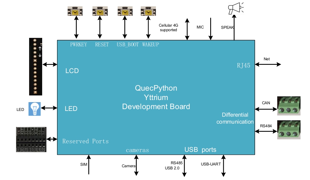
It integrates a rich set of interfaces including LCD display, camera capture, audio input/output, cellular network, 100 Mbps Ethernet, industrial-grade CAN/RS485 buses, and more. This makes it well-suited for IoT development, industrial communication, multimedia interaction, and various other application scenarios.
Hardware Description
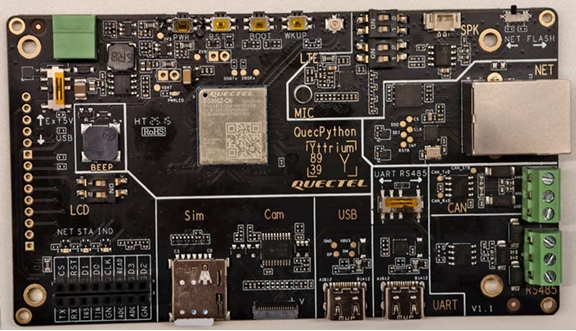
The main components and interface layout of the evaluation board are shown below:
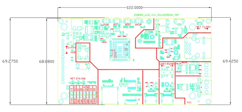
Evaluation board dimensions (top view):
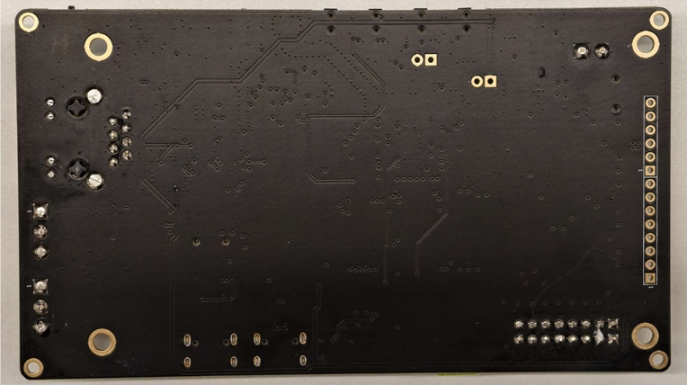
Top view and bottom view of the evaluation board:
Downloads
Board Resources
Basic Specifications
| Item | Specification |
|---|---|
| Package | PCBA |
| Dimensions (mm) | (122.0 ± 0.2) × (68.9 ± 0.2) × (1.6 ± 0.1) |
| Weight (g) | 49.2 ± 0.2 |
| Operating Temp. | -10 ~ +50 °C |
| Storage Temp. | -20 ~ +60 °C |
| Power Supply | USB Type-C 5V ± 5% / 3.81mm terminal block 5V ± 5% |
| Firmware Upgrade | USB / OTA |
Board Interfaces
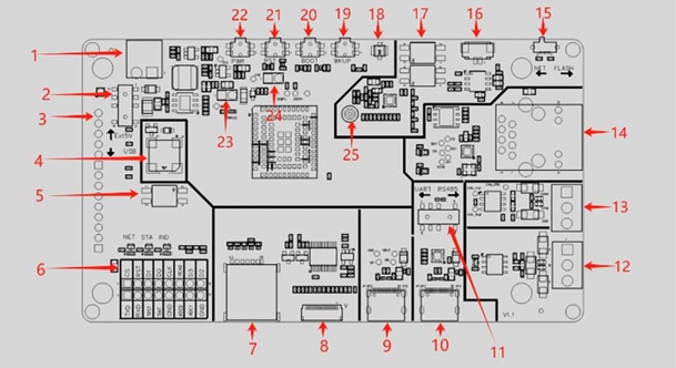
The detailed assignment of the board interfaces is as follows:
| No. | Interface | Description |
|---|---|---|
| Reserved Ports | ||
| 6 (J0702) | 1 × 8-Pin Header | MAIN_TXD, MAIN_RXD, LCD, CTP_INT, GND, ADC signals |
| 6 (J0703) | 1 × 8-Pin Header | QSPI_D3, QSPI_D2, LCD signals |
| Buttons & Switches | ||
| 2 | S0301 | Determines the board power source: toggle up for external DC 5V; toggle down for USB Type-C 5V |
| 5 | S0705 | DIP switch for LED_PWM4 / GPIO2 multiplexing. S0705 pins 2-4 ON + S0502 pins 1-3 OFF: LED_PWM4 controls IND_LED. S0705 pins 2-4 OFF + S0502 pins 1-3 ON: LED_PWM4 provides PWM4 audio output. S0705 pins 1-3 ON: GPIO2 controls buzzer BEEP |
| 11 | S0401 | Determines main UART routing: toggle left for USB Type-C UART; toggle right for RS485 |
| 15 | S0601 | DIP switch for SPI0 routing to NET or FLASH |
| 17 | S0501 / S0502 | S0501 ON + S0502 OFF: module PCM pins route through Codec to amplifier and speaker. S0501 OFF + S0502 ON: module PWM4 pin routes through filter circuit to amplifier and speaker |
| 19 | WAKEUP | Press to wake up the module |
| 20 | USB_BOOT | Press before power-on to enter forced download mode |
| 21 | RESET | Press to restart the module |
| 22 | PWRKEY | Press to power on the module |
| Communication | ||
| 12 | RS485 | RS485 connector: RS485_A, RS485_B, GND; half-duplex |
| 13 | CAN | CAN connector: CAN_H, CAN_L, GND; 1 Mbps data rate |
| 14 | Ethernet | 1 × RJ45 connector, supports 10/100 Mbps Ethernet; Link LED and Activity LED indicators |
| Camera | ||
| 8 (J0501) | 1 × 18-Pin FPC | Camera signal connector, supports 0.3 MP, SPI interface |
| Buzzer | ||
| 4 | BEEP | Buzzer; S0705 pins 1-3 ON: GPIO2 controls buzzer BEEP |
| LCD Display | ||
| 3 | 1 × 14-Pin Header | LCD resolution 320×480; 4.0-inch screen; capacitive touch panel; display interface: 4-Line SPI, driver ICST7796S; touch interface: I2C, driver FT6336U |
| Audio | ||
| 16 | SPEAK | Audio output, external speaker support |
| 25 | MIC | Onboard microphone SOM4013SL-G423L |
| USB Ports | ||
| 9 | USB Type-C | 1 × USB 2.0 Type-C, up to 480 Mbps data rate; can serve as power input |
| 10 | USB Type-C to UART | 1 × USB 2.0 Type-C, up to 12 Mbps data rate; converted to TTL via XR21B1411IL16 chip, connected to module main UART |
| LTE Module | ||
| 7 | SIM Card Slot | MUP-C7081-2, Nano SIM, 1.8V / 3.0V |
| 18 | Antenna Connector | Supports external LTE antenna |
| Power & Startup | ||
| 1 | External DC Input | 3.81mm terminal block, 5V ± 5% |
| 23 (J0203) | VBAT & VBAT12 Test Point | Remove resistor R0204 above this test point; connect an ammeter in series to measure module current |
| 24 | PWRKEY & GND Test Point | Short before power-on for auto-startup |
Reserved Port Pin Assignments
J0702 8-Pin Header Pin Assignments
| Header | Pin | Signal | Function |
|---|---|---|---|
| J0702 8-Pin | 1 | MAIN_TXD | Main UART transmit |
| J0702 8-Pin | 2 | MAIN_RXD | Main UART receive |
| J0702 8-Pin | 3 | LCD_SIG | LCD related signal |
| J0702 8-Pin | 4 | CTP_INT | Capacitive touch interrupt |
| J0702 8-Pin | 5 | GND | Ground |
| J0702 8-Pin | 6 | ADC0 | ADC input signal |
| J0702 8-Pin | 7 | ADC1 | ADC input signal |
| J0702 8-Pin | 8 | GND | Ground |
J0703 8-Pin Header Pin Assignments
| Header | Pin | Signal | Function |
|---|---|---|---|
| J0703 8-Pin | 1 | CS | SPI chip select |
| J0703 8-Pin | 2 | RST | SPI reset |
| J0703 8-Pin | 3 | QSPI_D1 | QSPI bus data 1 |
| J0703 8-Pin | 4 | QSPI_D0 | QSPI bus data 0 |
| J0703 8-Pin | 5 | CLK | LCD clock signal |
| J0703 8-Pin | 6 | READ | Ground |
| J0703 8-Pin | 7 | QSPI_D3 | QSPI bus data 3 |
| J0703 8-Pin | 8 | QSPI_D2 | QSPI bus data 2 |
Key Features
| Category | Description |
|---|---|
| USB Interface | 1 × USB 2.0 interface, up to 480 Mbps; 1 × USB Type-C connector, can serve as power input |
| UART | 1 × USB 2.0 interface, up to 12 Mbps; 1 × USB Type-C connector, can serve as power input; converted to UART via XR21B1411 chip, connected to module main UART |
| RS485 | Main UART converted to RS485 via a DPDT switch and RS485 transceiver (SIT3088E) |
| LCD Interface | LCD resolution 320×480; 4.0-inch screen; capacitive touch panel; display interface: 4-Line SPI, driver ICST7796S; touch interface: I2C, driver FT6336U |
| Audio — Speaker | 1 × CS8126, 2W Class-D audio amplifier, supports audio output |
| Audio — MIC | 1 × SOM4013SL-G423L onboard microphone, supports audio input |
| Audio — Codec | 1 × ES8311 Codec chip, connected to module via PCM and I2C for audio functionality |
| Compatible Audio Output | 1 × PWM signal and filter circuit designed for validating PWM audio output |
| Camera | 1 × 16-pin FPC connector; camera interface: SPI, driver GC032A; resolution: 0.3 MP |
| CAN | Integrated CAN controller via CAN transceiver SIT65HVD230, compliant with ISO 11898; supports up to 120 nodes on a single bus; max data rate 1 Mbps |
| Ethernet | 1 × RJ45 connector, supports 10/100 Mbps Ethernet; Link LED and Activity LED indicators |
| SIM Card | 1 × MUP-C7081-2 slot, supports Nano SIM; 1.8V and 3V dual voltage |
| Reserved Headers | 2 × 8-Pin headers; ADC, main UART, QSPI signals brought out |
| Buttons | 1 × PWRKEY power-on button; 1 × RESET reset button; 1 × BOOT forced download button; 1 × WAKEUP wake-up button |
| LED Indicators | PWRLED (red): module power indicator; INDLED (green): module operation indicator, user-programmable |
| Buzzer | 1 × Beep buzzer |
| Firmware Upgrade | USB / OTA |
Onboard Buttons and Indicators
The board features 4 functional buttons and 2 status LEDs:
- PWRKEY: Power-on button. Long press to power on the module.
- RESET: Reset button. Press to trigger a module restart.
- BOOT: Forced download button. Press and hold before power-on to enter forced firmware download mode.
- WAKEUP: Wake-up button. Press to wake the module from sleep.
- PWRLED: Red power indicator. Stays lit when the module is properly powered.
- INDLED: Green operation indicator. Supports user-defined functionality for operation status indication.
Quick Start Guide
Hardware Preparation
Step 1: Required Items
Items required before getting started:
- Evaluation Board
- USB Cable (USB-A to USB Type-C)
- PC (Windows 10)
- SIM Card
- 4G Antenna
Step 2: Antenna & SIM Installation
Attach the provided antenna to the MAIN antenna port and insert the SIM card into the SIM card slot.
Step 3: Connect the Board
Connect the board to your PC using a USB Type-C cable via the Type-C/Micro USB port for power supply.
When the PWR LED is constantly lit, the board is properly powered.
Step 4: Power On
Long-press PWRKEY to power on. Before pressing PWRKEY, ensure the supply voltage is stable. It is recommended to wait at least 30 ms between power-on and pressing PWRKEY.
If auto power-on is required and the shutdown function is not needed, short the two pins labeled PWK_AUTO on the 10-Pin header.
If PWK_ON is shorted in the previous step, the board will power on automatically without long-pressing PWRKEY. After startup, the NET LED will blink, indicating the board has powered on normally.
Driver Installation
- Download the QuecPython USB Driver from QuecPython Official Drivers.
- Extract and run
setup.exeorsetup.bat. - Verify installation in Device Manager (look for ports starting with "Quectel USB"). Ignore unrelated devices such as "Mobile ECM Network Adapter" or "CDC Ethernet Control Model (ECM)".
Tool Installation
QPYcom: The dedicated QuecPython development and debugging tool for code debugging, log analysis, file transfer, firmware burning, and firmware merging. Download from QuecPython Tools. No installation required — extract and use directly.
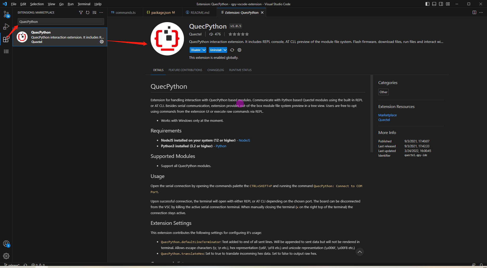
VSCode Plugin: Search for "QuecPython" in the Visual Studio Code extensions marketplace to install the plugin, which provides code hints, code completion, and serial debugging features.
Firmware Burning
Firmware Download: Get the latest QuecPython firmware from the QuecPython Firmware page.
Select the firmware that matches your module model. The firmware file name follows the pattern
QPY_OCPU_<version>_<module_model>_FW. Download the latest version unless you have specific requirements.The downloaded package is a ZIP file. Extract it (avoid paths containing Chinese characters, spaces, or special characters) to obtain the
.binfirmware file and a.mdchangelog.
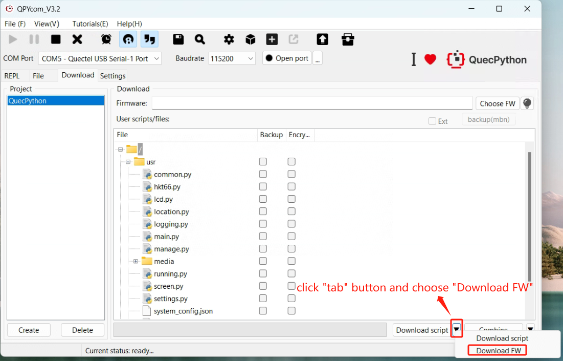
- Burning Steps:
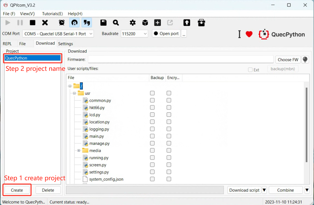
- Open QPYcom, go to the download page, and click Create to set up a new firmware project.
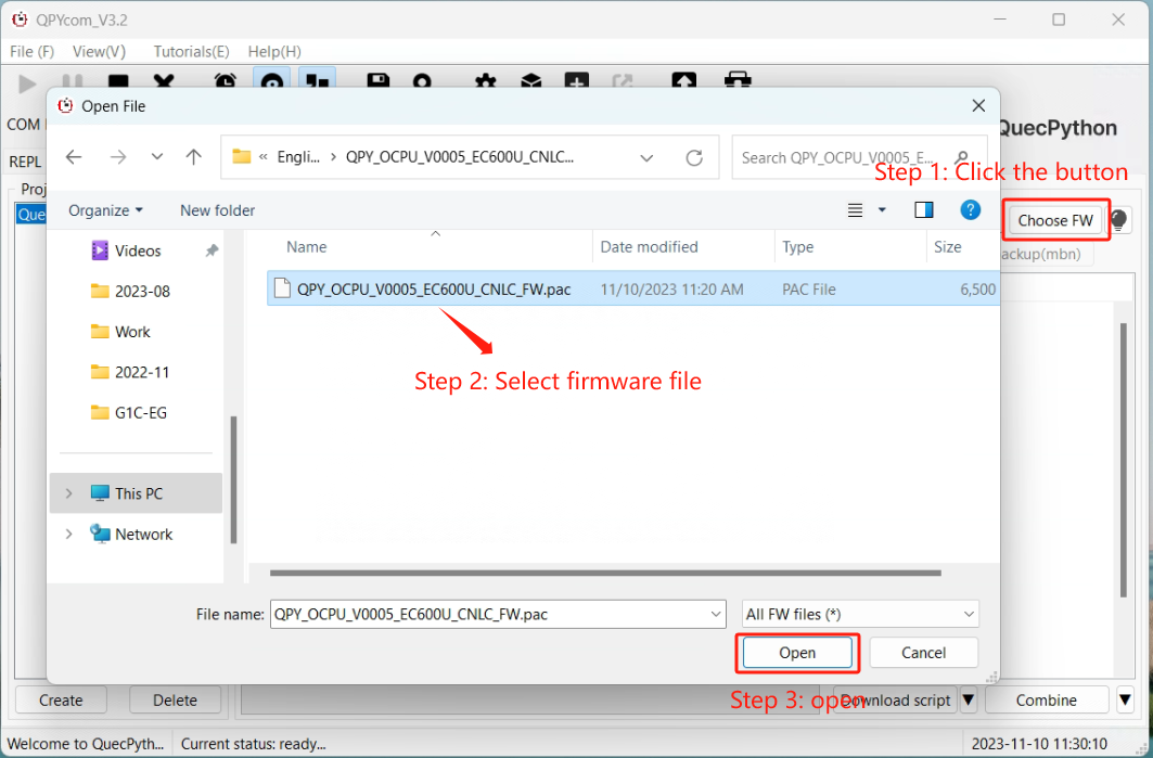
- Select the
.binfirmware file for your module model. - Set the download mode to "Download FW".
- Click Download FW to start burning. A progress bar will show the status, and a dialog will confirm completion.
REPL Debugging
- Connect via QPYcom — select the Quectel USB REPL Port and open the "Interactive" tab.
- Click "Open Serial Port" and test with
print('hello world').
>>> print('hello world')
hello world
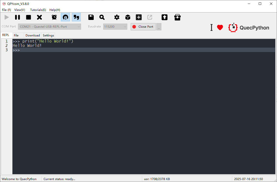
Note: When using the interactive interface, ensure you type in English characters — Chinese characters will be filtered.
First Script Development
Writing a Script
Create helloworld.py:
print("hello world")
Download the file to the module using QPYcom and run it.
File Transfer
Method 1 — Drag and Drop:
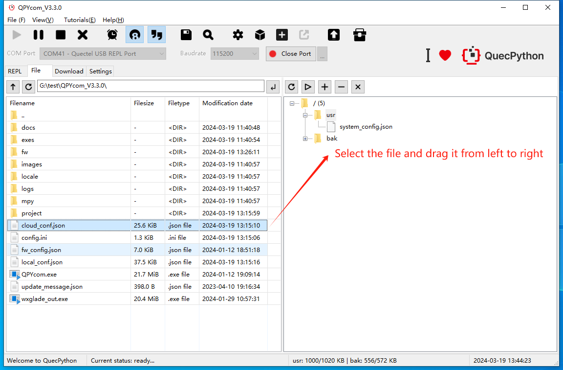
- Open the serial port and use the +/− buttons on the file page to upload and delete files,
- or drag and drop files/folders from the left (local) pane to the right (module) pane.
Method 2 — Download Script:
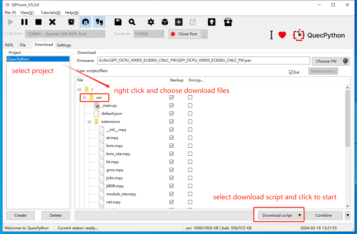
- Create a user project and add your script files in the "User Script" area.
- Set the download mode to "Download Script" and click to start. A progress bar will show the download status.
Running Scripts
Execute via REPL:
import example
example.exec("/usr/helloworld.py")
Or use QPYcom's file page: select the script file and click the ▶ button to execute.
Stopping Program Execution
How to stop a running program. The following methods are provided according to the type of the running script file:
| Is the program name main.py? | Does the program contain a dead loop? | Does the program use multiple threads? | Stopping Steps |
|---|---|---|---|
| ✓ | ✓ | ✓ | (1) Press Ctrl + A to enter RAW mode (2) Press Ctrl + D to restart the QuecPython VM (3) Press Ctrl + B to return to normal interactive mode (4) If the above fails, re-burn the firmware |
| ✓ | ✓ | ✗ | (1) Press Ctrl + C to interrupt execution (2) If the above fails, re-burn the firmware |
| ✓ | ✗ | ✓ | (1) Press Ctrl + A to enter RAW mode (2) Press Ctrl + D to restart the QuecPython VM (3) Press Ctrl + B to return to normal interactive mode (4) If the above fails, wait for the program to finish |
| ✓ | ✗ | ✗ | (1) Press Ctrl + C to interrupt execution (2) If the above fails, re-burn the firmware |
| ✗ | ✓ | ✓ | (1) Press Ctrl + D to restart the QuecPython VM (2) If the above fails, directly restart the module |
| ✗ | ✓ | ✗ | (1) Press Ctrl + D to restart the QuecPython VM (2) If the above fails, directly restart the module |
| ✗ | ✗ | ✓ | (1) Press Ctrl + C to interrupt execution (2) If the above fails, re-burn the firmware or directly restart the module |
| ✗ | ✗ | ✗ | (1) Press Ctrl + C to interrupt execution (2) If the above fails, re-burn the firmware or directly restart the module |