

 English
HCM010S&HCM511S Series Open(SDK) Quick Start Guide
Introduction
Quectel HCM010S, HCM010S-E, HCM511S and HCM511S-E modules support open solution, which can simplify the software design and development process for IoT applications. For detailed information about the aforementioned open solution, please visit https://github.com/SiliconLabs/gecko_sdk.
This document is applicable to open solution based on SDK build environment. It is a quick start guide for HCM010S, HCM010S-E, HCM511S and HCM511S-E modules. It outlines the compilation environment setup, the application development and compilation, firmware flashing, program debugging, OTA upgrade and Quectel MAC address usage for HCM010S, HCM010S-E, HCM511S and HCM511S-E modules.
Set up Compilation Environment
Hardware Environment
| Hardware | Quantity |
|---|---|
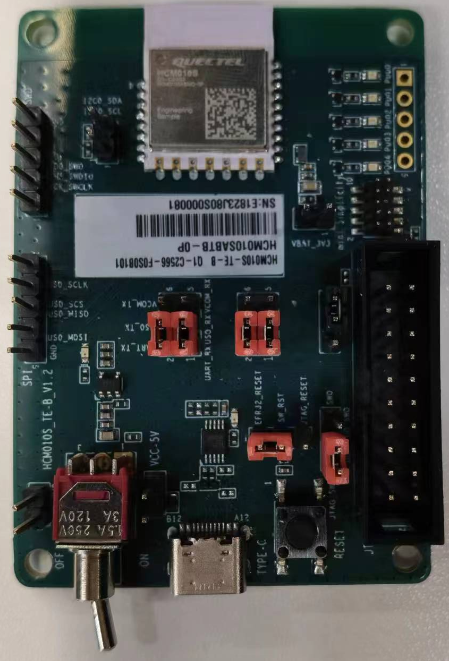
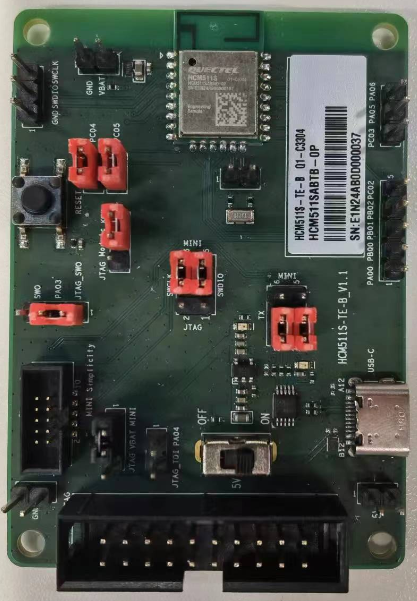
| HCM010S-TE-B development board, HCM010S-E-TE-B development board, HCM511S-TE-B development board or HCM511S-E-TE-B development board | 1 |
| HCM010S, HCM010S-E, HCM511S or HCM511S-E module | 1 |
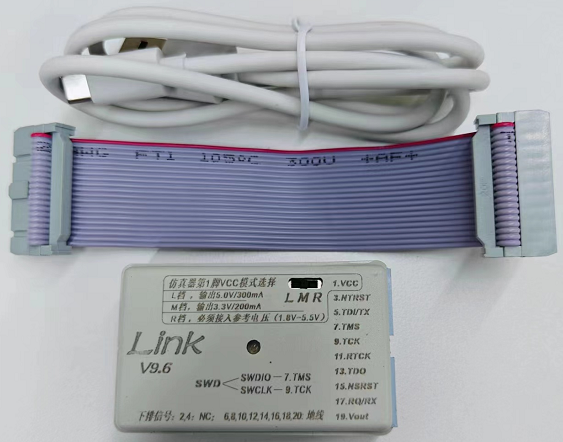
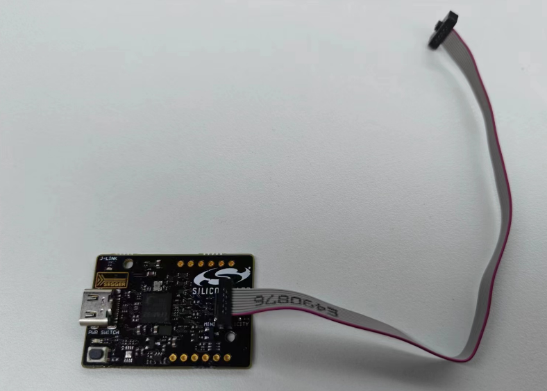
| J-Link debugger/ SI-DBG1015A Simplicity Link debugger | 1 |
| USB cable (connecting the module's development board to PC) | 1 |
| Cable connecting the J-Link debugger or SI-DBG1015A Simplicity Link debugger to the module development board | 1 |
| PC | 1 |
| Mobile phone | 1 |
NOTE
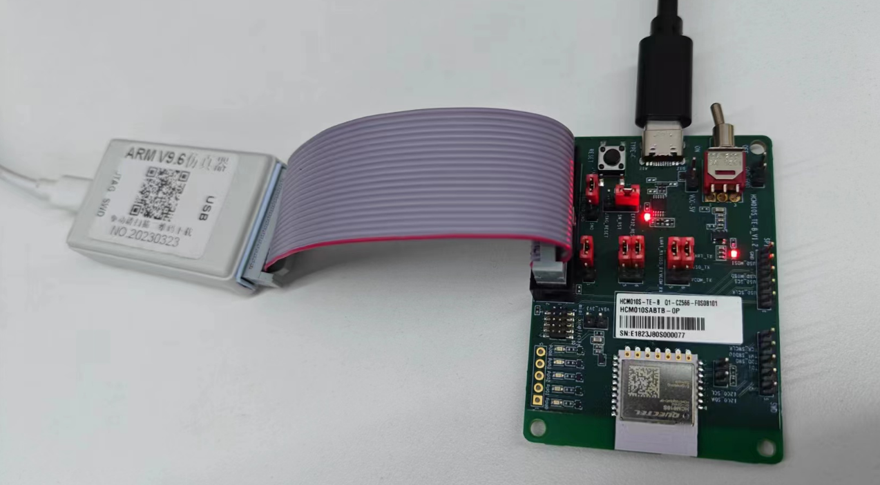
- This document uses J-Link debugger as an example and introduces module application development, firmware flashing, and program debugging. For J-Link debugger connection steps and JTAG interface jumper configuration.
- If you use SI-DBG1015A Simplicity Link debugger, refer to *documents [1], [2], [3]* and *[4]*to connect the module and SI-DBG1015A Simplicity Link debugger.
Software Environment
| Type | Description |
|---|---|
| Tool | - Install EFR Connect APP on mobile phone - Install Simplicity Studio on PC |
| SDK | gecko_sdk-gsdk_4.2 |
NOTE
- For details about EFR Connect APP, refer to https://www.silabs.com/documents/public/software/android-efr-connect.apk.
- To learn how to use Simplicity Studio, refer to https://docs.silabs.com/simplicity-studio-5-users-guide/5.9.1/ss-5-users-guide-getting-started.
- This document uses gecko_sdk-gsdk_4.2 as an example. You can download the corresponding SDK from https://github.com/SiliconLabs/gecko_sdk according to your needs.
- For additional example resources, visit https://github.com/SiliconLabs.
Install Simplicity Studio
- Download Simplicity Studio toolkit from https://www.silabs.com/developers/simplicity-studio.

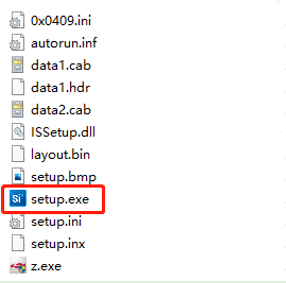
The downloaded Simplicity Studio toolkit is as follows:

- After extracting the SimplicityStudio-5.iso toolkit, double-click setup.exe in the toolkit to install it.
Install development packages.
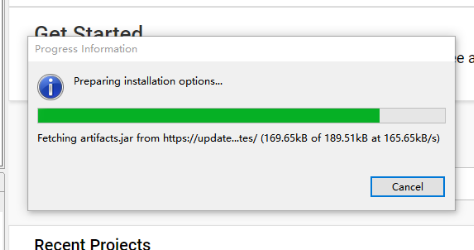
- After Simplicity Studio is installed, open Simplicity Studio. The "Progress Information" interface will be displayed as shown in the following figure. Wait until the Simplicity Studio is loaded successfully.
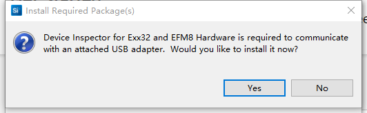
If the following "Install Required Package(s)" prompt appears, click "Yes".
- Once the "Installation Manager" interface is displayed, click "Update All" to start the installation.
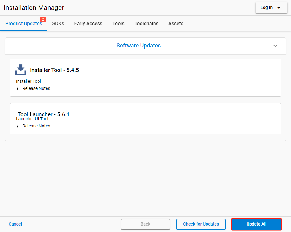
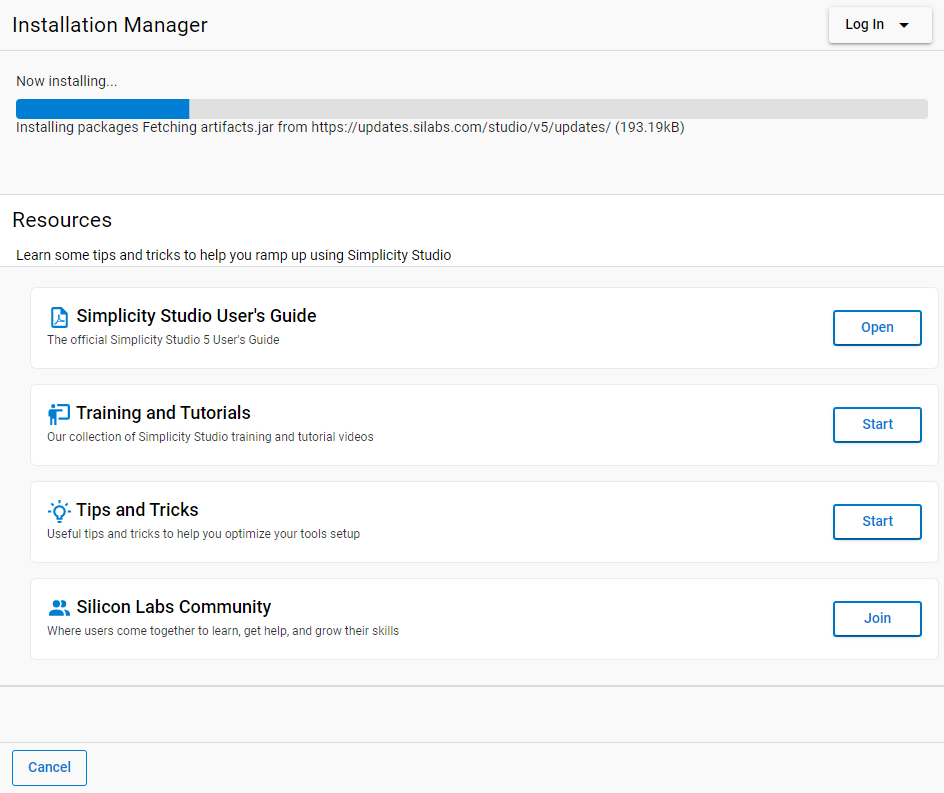
The installation interface is as follows:
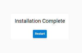
- After the installation is completed, the following window will appear. Click "Restart" to finalize the process.
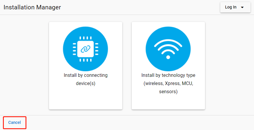
- After the Simplicity Studio tool restarts, the "Installation Manager" interface is displayed as shown below. Click "Cancel" in the lower-left corner to close this interface.
Update Software Package
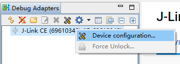
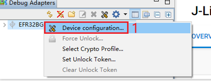
- In the "Debug Adapters" section of the Simplicity Studio main interface, locate the J-Link debugger (such as J-Link CE (69610348) in the figure below). Right-click the J-Link debugger and select "Device configuration...".
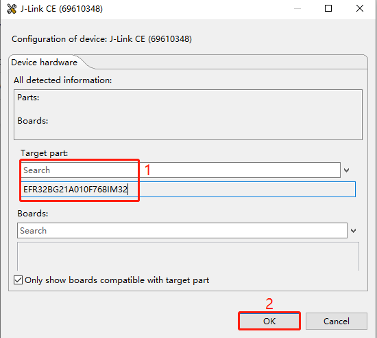
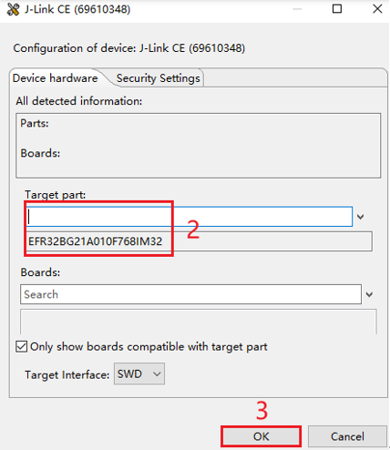
- In the pop-up J-Link CE (69610348) configuration interface, enter and select the corresponding chip model in the "Target part" text box, and then click "OK". (The chip model varies depending on the used module model. For details, contact Quectel Technical Support.)
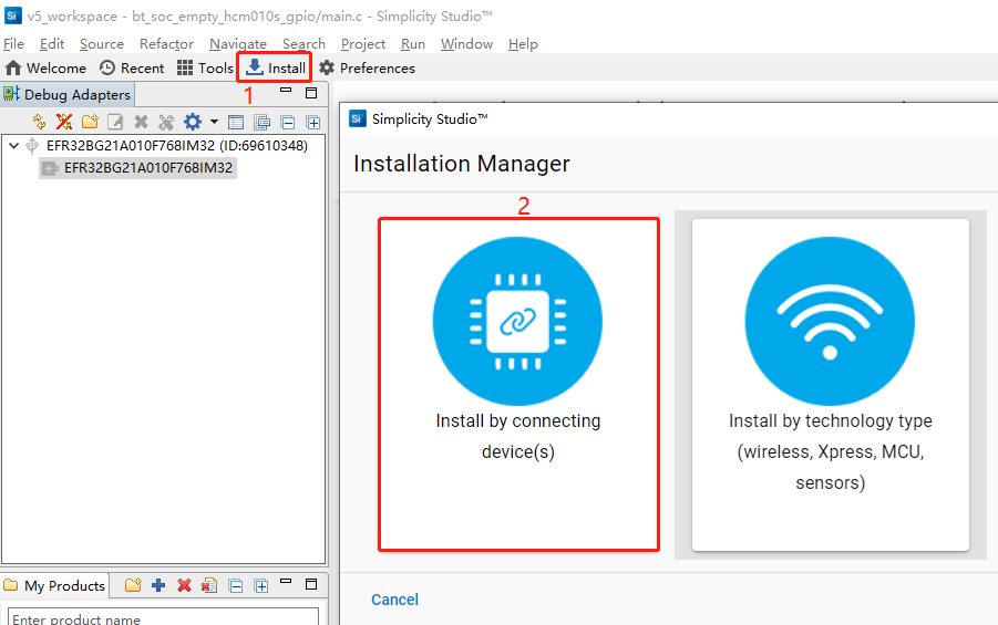
- Click "Install" in the tool interface, and the "Installation Manager" window will pop up. Select "Install by connecting device(s)" on the left side of the window.
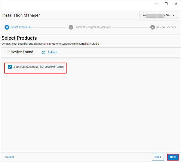
- Select the J-Link debugger and then click "Next".
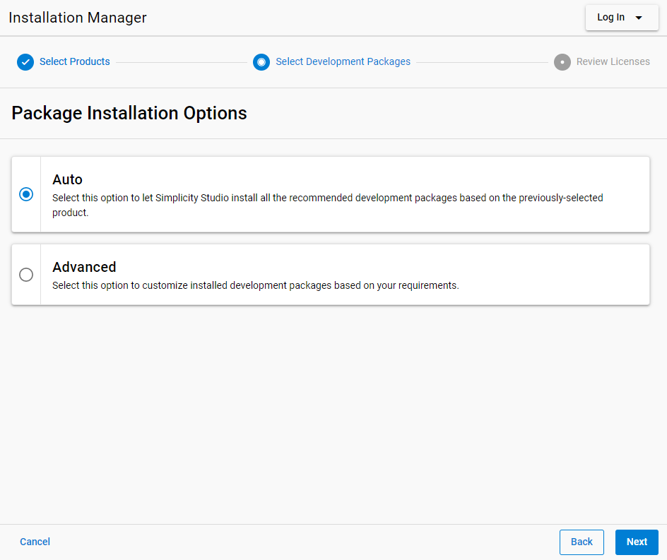
- Select "Auto" in the "Package Installation Options" section and click "Next".
- Select "Accept all agreements" and "Accept this agreement", and then click "Next".

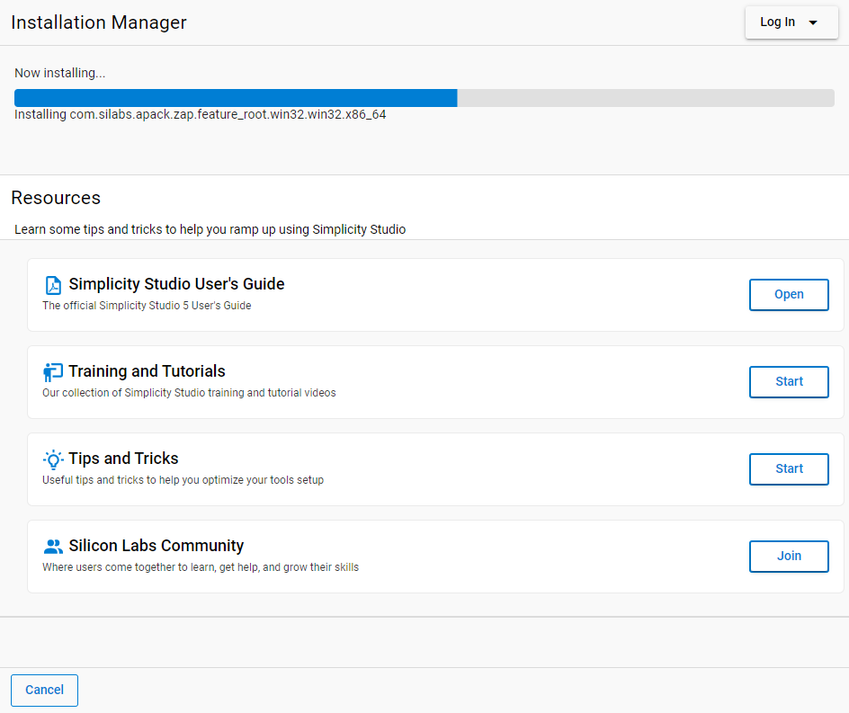
The following installation interface is displayed. Wait for the installation to complete.
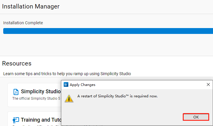
- After the installation is completed, the following prompt to restart Simplicity Studio will appear. Click "OK" to restart Simplicity Studio.
Download and Add SDK
Execute git clone https://github.com/SiliconLabs/gecko_sdk.git to download gecko_sdk-gsdk_4.2 and then extract the package (Extraction path should not contain Chinese characters).
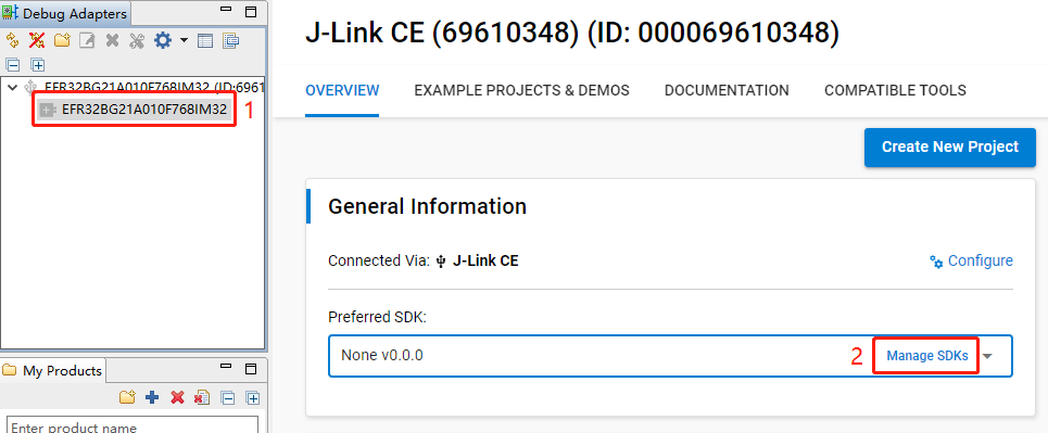
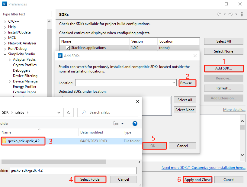
Select the J-Link debugger in the "Debug Adapters" section on the left of Simplicity Studio main interface. The device information is displayed on the right of the tool. Select "OVERVIEW" and click "Manage SDKs" to open the "SDKs" page.
- Perform the following steps to add the SDK: Click "Add SDK..." > Click "Browse..." > Select gecko_sdk- gsdk_4.2 folder > Click "Select Folder" > Click "OK" > Click "Apply and Close".
Develop Application
This chapter explains how to develop applications.
Application Development Example for HCM010S/HCM010S-E
This chapter explains how to develop SoC Blinky, Sleeptimer Bare-metal and Soc Empty applications based on HCM010S-TE-B.
Table 3: Pin Mapping Relationship for HCM010S and HCM010S-E Modules
| HCM010S Pin No. | HCM010S-E Pin No. | Pin Name | Chip Pin Name |
|---|---|---|---|
| - | 1 | GND | GND |
| - | 2 | ANT_BT | RF2G4 |
| 1 | 3 | GND | GND |
| 2 | 4 | USART_TXD | PA05 |
| 3 | 5 | USART_RXD | PA06 |
| 4 | 6 | SWDIO | PA02 |
| 5 | 7 | SWCLK | PA01 |
| 6 | 8 | GPIO4 | PB01 |
| 7 | 9 | GPIO5 | PB00 |
| 8 | 10 | GPIO1 | PA00 |
| 9 | 11 | GPIO6 | PC02 |
| 10 | 12 | GPIO7 | PC01 |
| 11 | 13 | GPIO8 | PC00 |
| 12 | 14 | GPIO9 | PC03 |
| 13 | 15 | GND | GND |
| 14 | 16 | RESET_N | RESET_N |
| 15 | - | GPIO12 | PD01 |
| - | 17 | RESERVED | PD01 |
| 16 | 18 | VBAT | VBAT |
| 17 | 19 | GND | GND |
| 18 | 20 | GPIO13 | PD04 |
| 19 | 21 | GPIO14 | PD03 |
| 20 | 22 | GPIO15 | PD02 |
| 21 | 23 | GPIO10 | PC04 |
| 22 | 24 | GPIO11 | PC05 |
| 23 | - | GPIO16 | PD00 |
| - | 25 | RESERVED | PD00 |
| 24 | 26 | GPIO2 | PA03 |
| 25 | 27 | GPIO3 | PA04 |
NOTE
See *documents [5]* and *[6]* for detailed pin information.
Bluetooth - SoC Blinky
This chapter uses the development of SoC Blinky application named bt_soc_blinky_010s as an example to describe the application development process. bt_soc_blinky_010s controls the turning on or off of LED1 light on HCM010S-TE-B by sending data after a Bluetooth connection is established.
Create Project
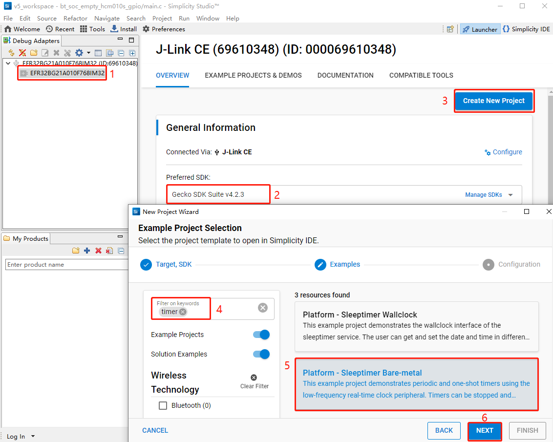
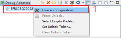
- In the "Debug Adapters" section of the Simplicity Studio main interface, locate the J-Link debugger (such as J-Link CE (69610348) in the figure below). Right-click the J-Link debugger and select "Device configuration...".
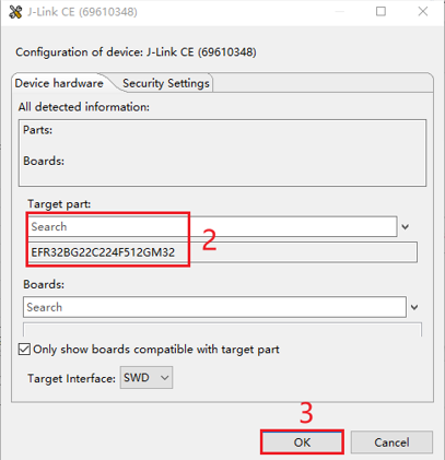
- In the pop-up J-Link CE (69610348) configuration interface, enter and select the corresponding chip model in the "Target part" text box, and then click "OK". (The chip model varies depending on the used module model. For details, contact Quectel Technical Support.)
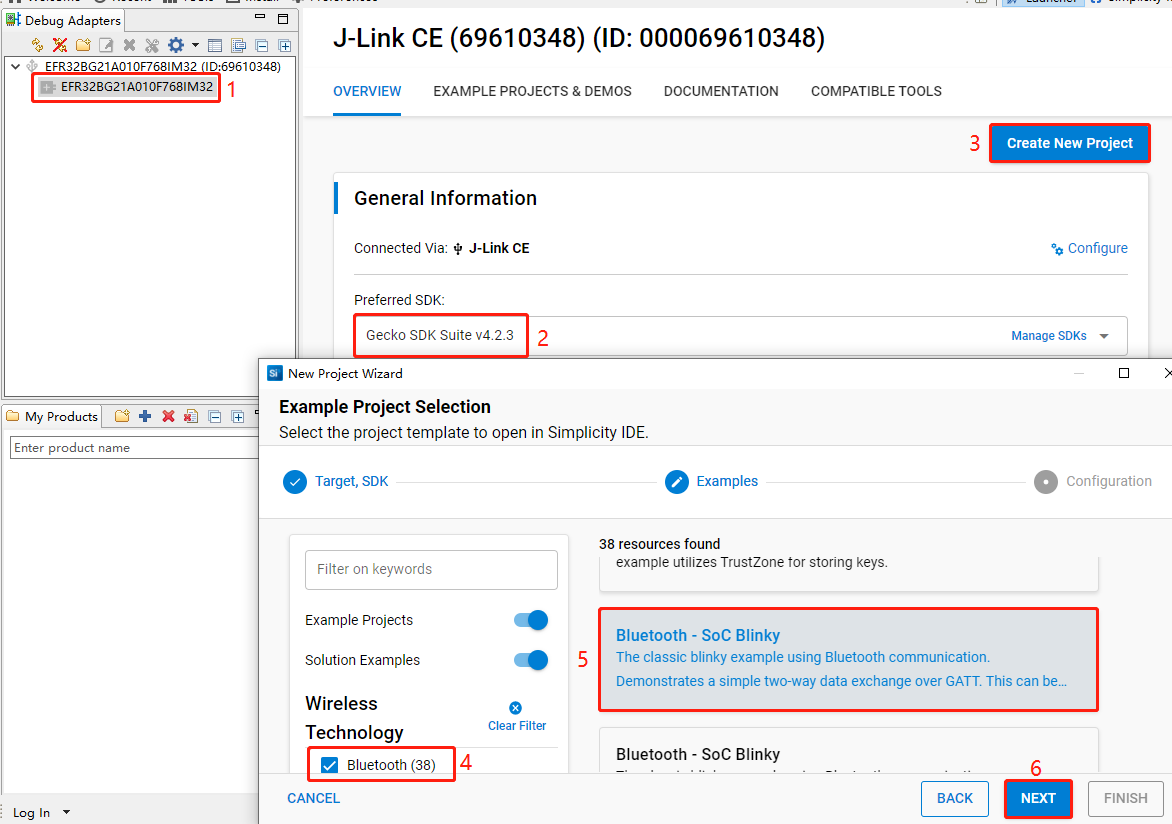
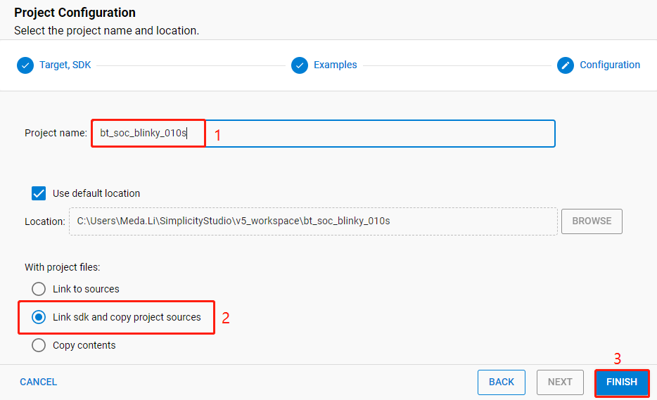
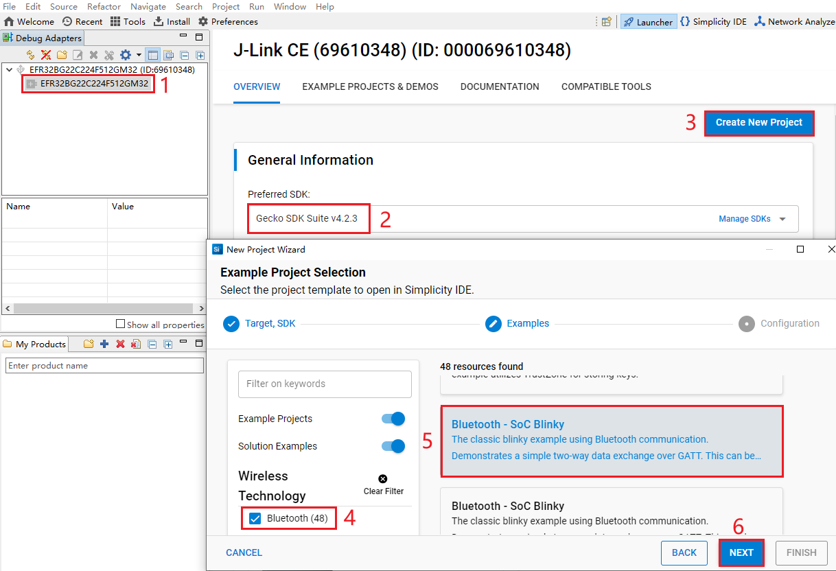
- Select the device on the Simplicity Studio tool interface > Select Gecko SDK Suite v4.2.3 (that is, gecko_sdk-gsdk_4.2) > Click "Create New Project" > In the "New Project Wizard" window that pops up, follow the prompts to navigate to the "Example Project Selection" interface, and select the "Bluetooth" option in the lower-left corner > Select "Bluetooth - SoC Blinky" > Click "NEXT" to open the "Project Configuration" interface.
- On the "Project Configuration" interface, set the project name as "bt_soc_blinky_010s" (the project path cannot be browsed and it will change based on the project name), select "Link sdk and copy project sources", and click "FINISH".
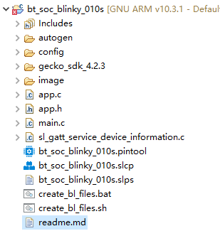
The created bt_soc_blinky_010s project is as follows:
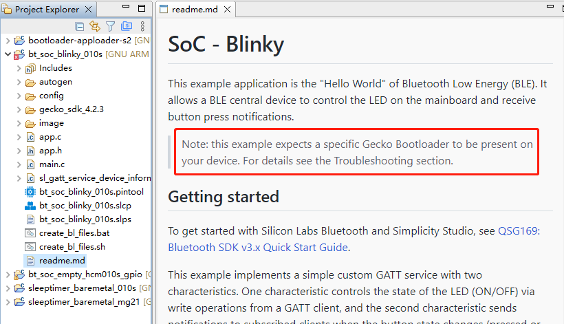
After the project is created, the readme.md file of bt_soc_blinky_010s is displayed, as shown in the following figure.
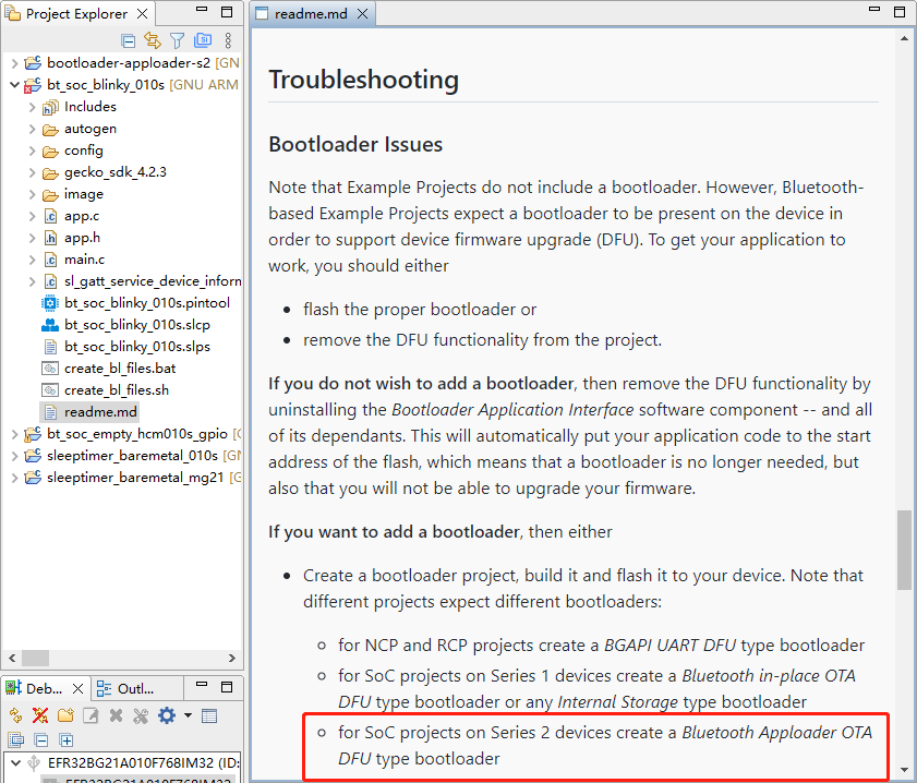
- Create a bootloader project. According to the readme.md file, the bt_soc_blinky_010s project requires a bootloader. As shown in the Troubleshooting section in the following figure, the required bootloader type is Bluetooth Apploader OTA DFU type bootloader.
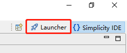
- Click "Launcher" in the upper-right corner of the tool interface to return to the initial interface (to switch back to the development environment click "Simplicity IDE").
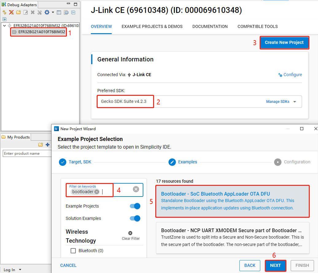
- Perform the following steps to choose the bootloader: Select the device > Choose Gecko SDK Suite v4.2.3 > Click "Create New Project" > Enter "Bootloader" in the "Filter on keywords" search box on the left side of "Example Project Selection" interface > Select "Bootloader - SoC Bluetooth AppLoader OTA DFU" from the search result > Click "Next".
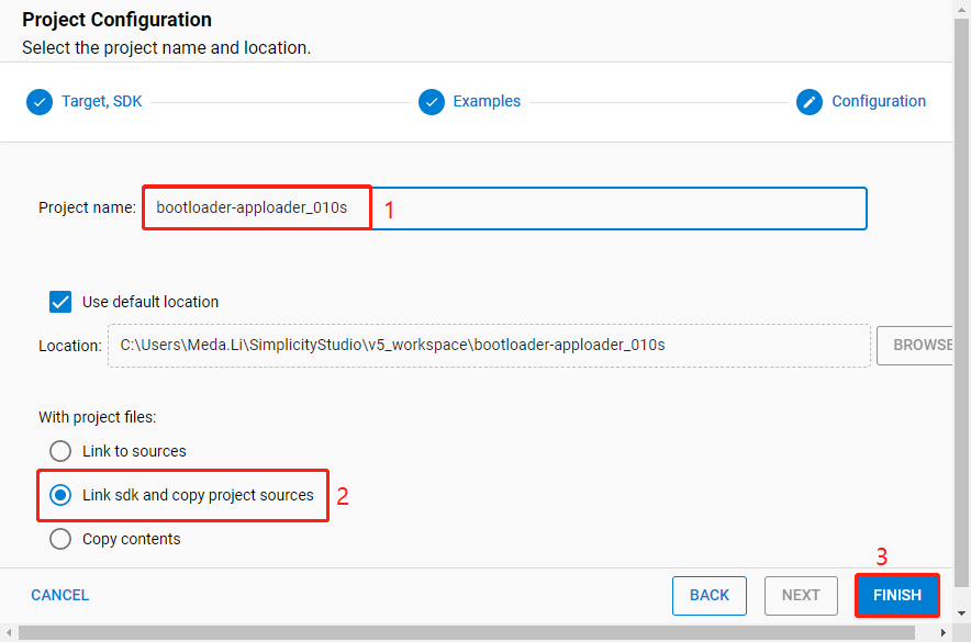
- On the "Project Configuration" interface, set the project name to "bootloader-apploader_010s" (the project path cannot be browsed and it will change based on the project name), select "Link sdk and copy project sources", and click "FINISH".
The created bootloader-apploader_010s project is as follows. For more details about bootloader, see https://www.silabs.com/documents/public/user-guides/ug489-gecko-bootloader-user-guide-gsdk-4.pdf.
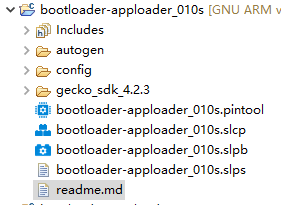
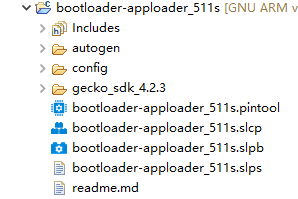
Table 4: Project Directory Structure
| Directory | Description |
|---|---|
| autogen | Stores the files generated automatically in IDE. |
| config | Stores project configuration files. |
| gecko_sdk_4.2.3 | Stores the SDK of chip manufacturer. |
| GNU ARM 10.3.1 - Default | Stores the files such as .hex file generated after compilation. |
| xxx.pintool | Tool for configuring pins. |
| xxx.slcp | Used to install and configure components. |
| readme.md | Documentation for the examples. |
NOTE
File directories vary according to software projects. This table lists only the file directories that are included in all software projects.
Configure Project
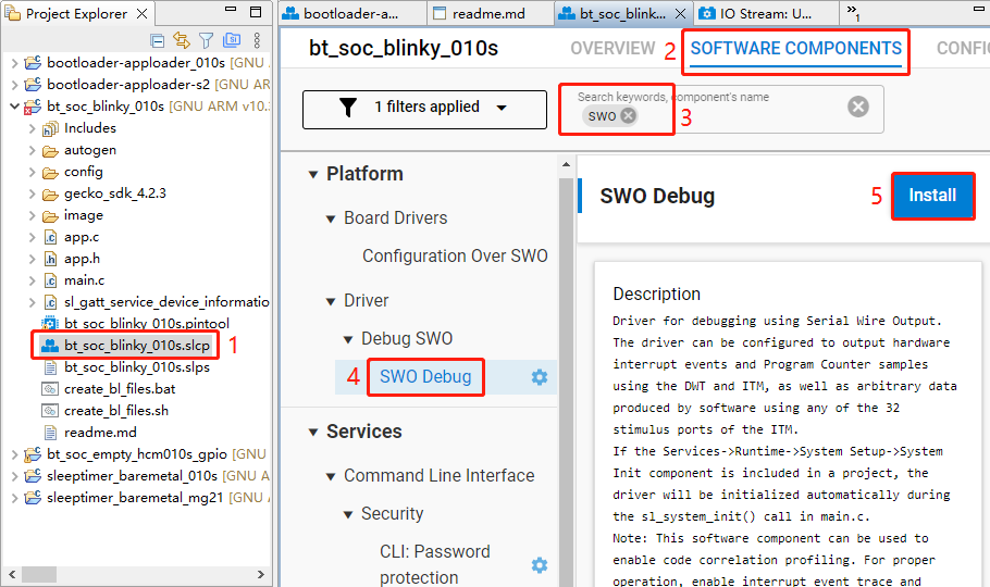
- Find and install the required components.
In bt_soc_blinky_010s project, find and double-click bt_soc_blinky_010s.slcp to go to "bt_soc_blinky_010s" page. Select the "SOFTWARE COMPONENTS" tab and enter "SWO" in the search box. Choose "SWO Debug" from the search results and then click "Install" to install the SWO Debug component.
Configure the components that are not configured.
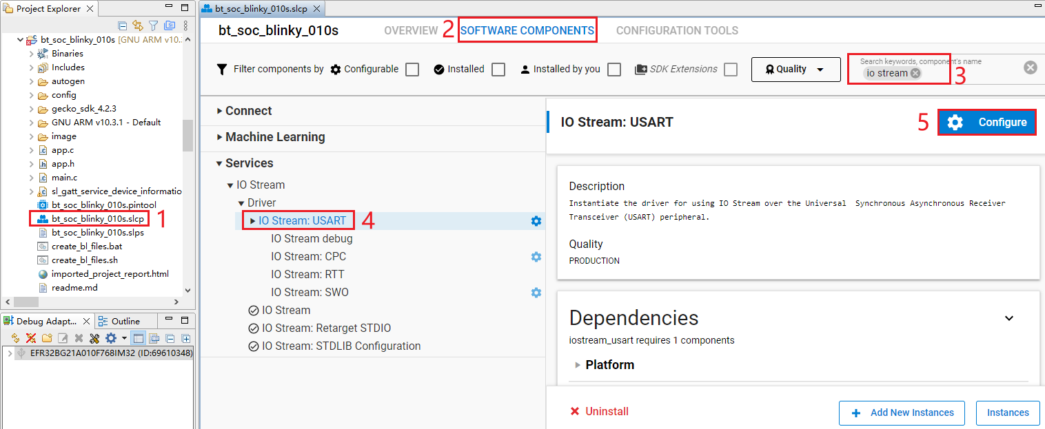
- Double-click bt_soc_blinky_010s.slcp to go to "bt_soc_blinky_010s" page. Select the "SOFTWARE COMPONENTS" tab and enter "io stream" in the search box. Choose "IO Stream: USART" from the search results and then click "Configure" to open the IO Stream: USART component configuration interface.
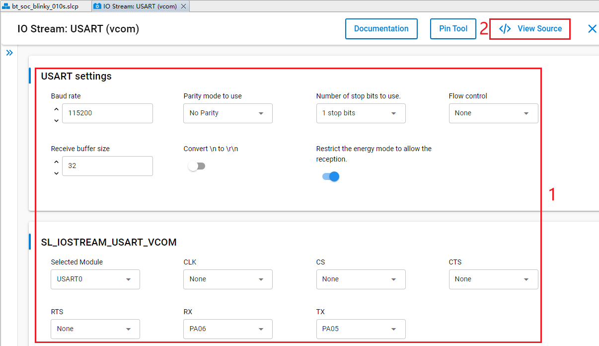
Configure the IO Stream: USART component as outlined in red below, then click "</> View Source".
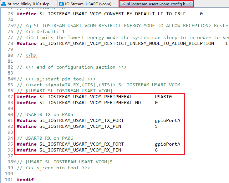
The sl_iostream_usart_vcom_config.h file shown in the following figure will appear, and the code lines outlined in red will be generated after the IO Stream: USART component is configured.
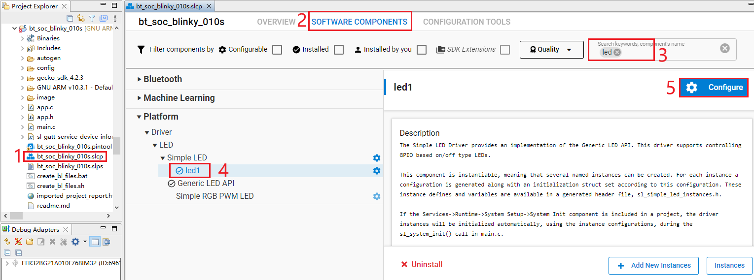
- Double-click bt_soc_blinky_010s.slcp to go to "bt_soc_blinky_010s" page. Select the "SOFTWARE COMPONENTS" tab and enter "led" in the search box. Choose "led1" (If the SDK version is different, the led name displayed in this step may be different, but the function is the same) from the search results, and then click "Configure" to open the Simple LED (led1) component configuration interface.
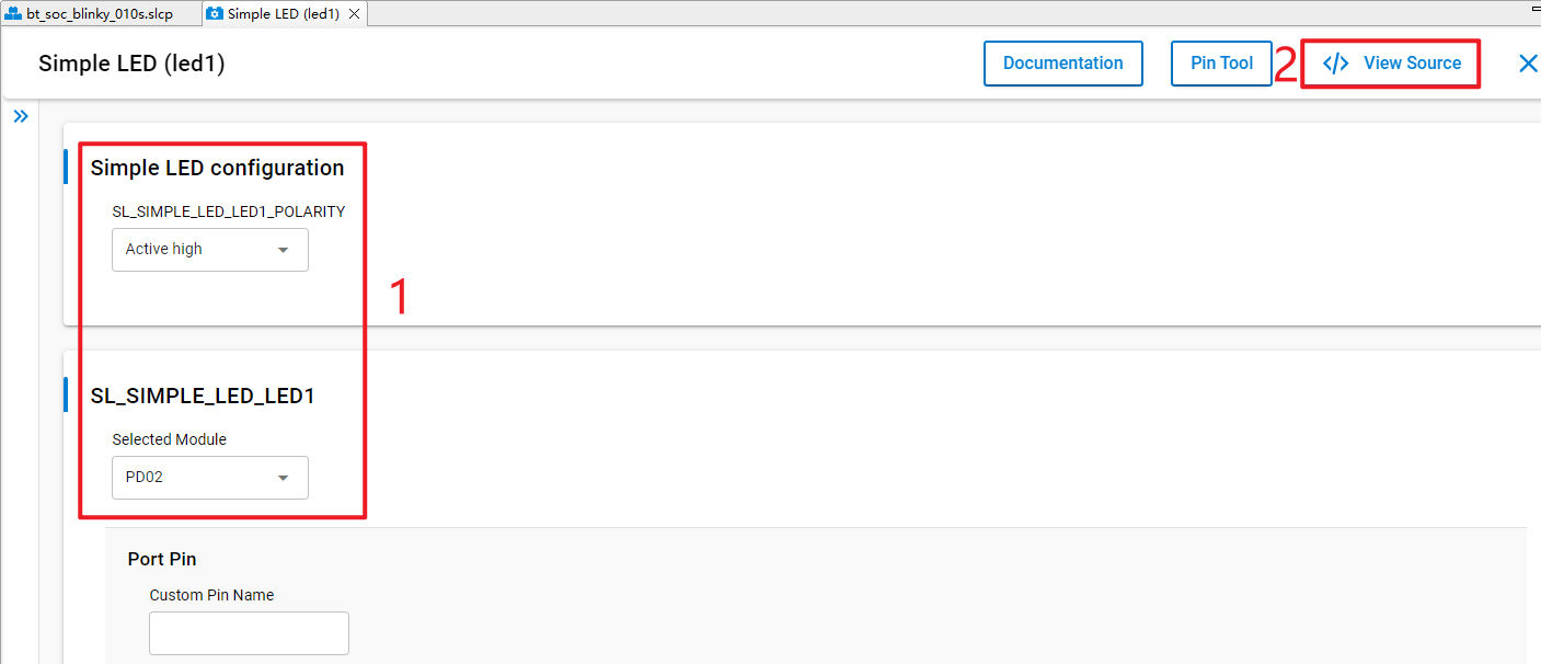
Configure the Simple LED (led1) component and select PD02 as LED1 as outlined in red below, then click "</> View Source".
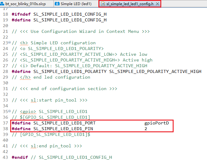
The sl_simple_led_led1_config.h file shown in the following figure will appear, and the code lines outlined in red will be generated after the Simple LED (led1) component is configured.
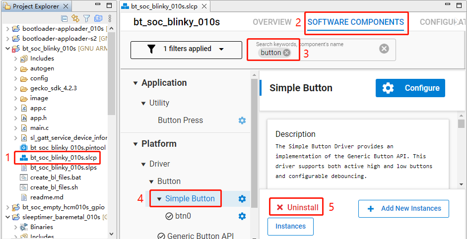
The HCM010S-TE-B has only one reset button and no other button, so btn0 should be removed. Perform the following operations to remove btn0:
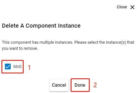
- Double-click bt_soc_blinky_010s.slcp to go to the "bt_soc_blinky_010s" interface. Select the "SOFTWARE COMPONENTS" tab and enter "button" in the search box. Choose "Simple Button" from the search results, and then click "Uninstall".
- The following interface appears after you click "Uninstall". Select "btn0", and then click "Done".
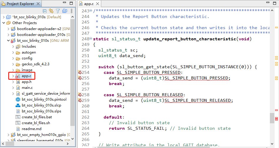
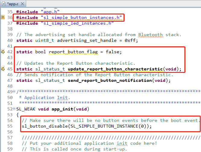
- In bt_soc_blinky_010s project, find app.c and double-click it to open it, and then delete update_report_button_characteristic().
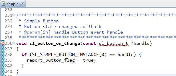
- Delete sl_button_on_change() from app.c.
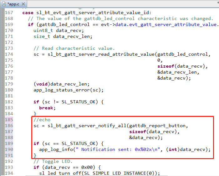
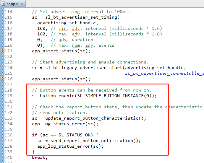
- Add the code lines outlined in red to the proper location (above the "Toggle LED" part) in app.c file.
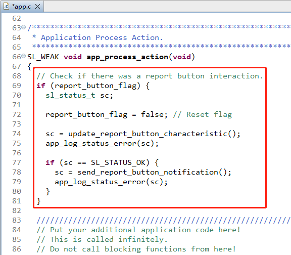
- Delete the code lines outlined in red from app.c.
- Complete additional configurations.
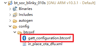
To view or modify the GATT configuration file gatt_configuration.btconf, expand the target project > config > btconf, and then double-click gatt_configuration.btconf to open it.
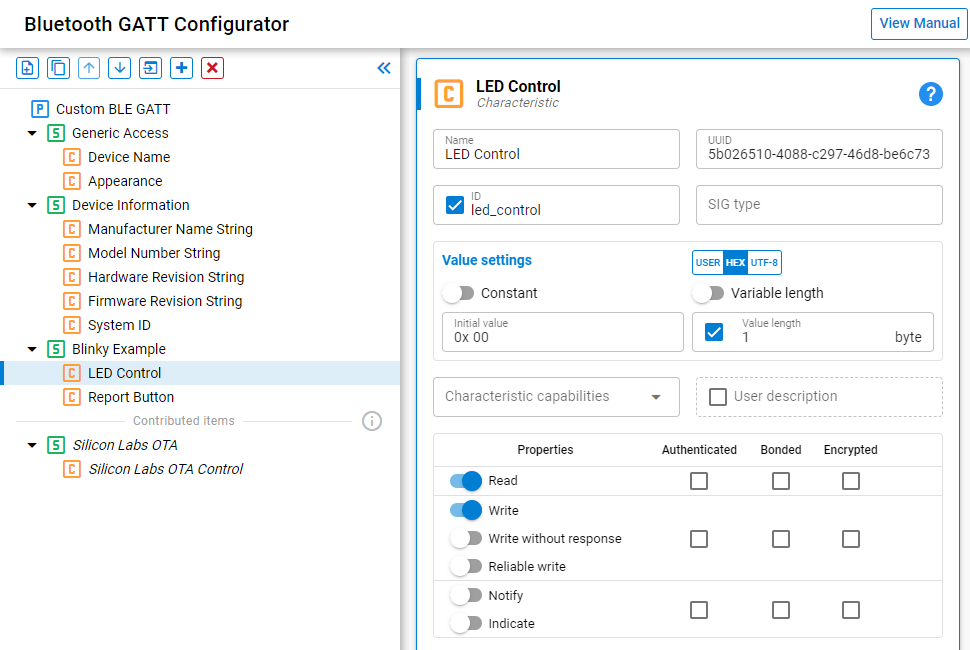
Program Description


Platform - Sleeptimer Bare-metal
This chapter describes the application development process using the development of Sleeptimer Bare-metal application named sleeptimer_baremetal_010s in a bare-metal environment as an example.
The example application creates two periodic timers and one single-shot timer. The single-shot timer and one periodic timer switch the state of the two LED lights (on/off), and the other periodic timer prints the remaining time for the two timers mentioned above. You can view the related logs in the debugging window of a serial port tool.
Create Project
Configure device by following *Steps 1* and *2 in Chapter 3.1.1.1*.
Select the device on the Simplicity Studio tool interface > Select Gecko SDK Suite v4.2.3 (that is, gecko_sdk-gsdk_4.2) > Click "Create New Project" > In the "New Project Wizard" window that pops up, follow the prompts to navigate to the "Example Project Selection" interface, and enter "timer" in the "Filter on keywords" search box on the left > Select "Platform - Sleeptimer Bare-metal" > Click "NEXT" to go to the "Project Configuration" interface.
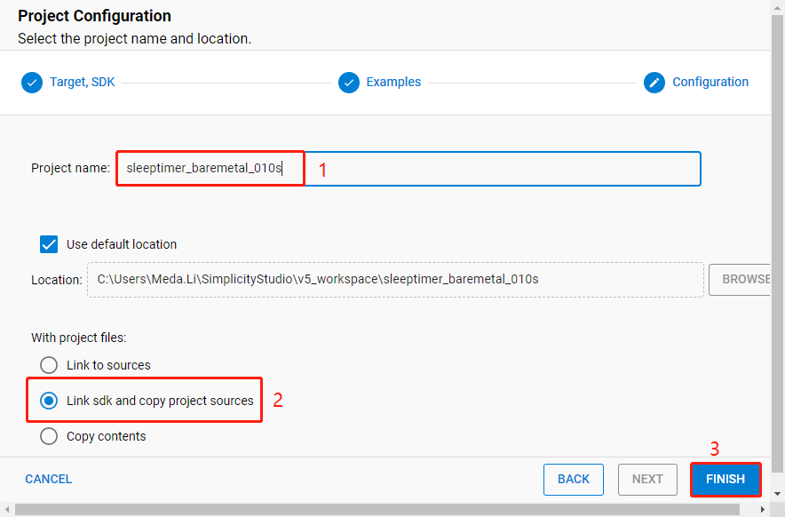
- On the "Project Configuration" interface, set the project name as "sleeptimer_baremetal_010s" (the project path cannot be browsed and it will change based on the project name), select "Link sdk and copy project sources", and click "FINISH".
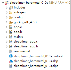
The created sleeptimer_baremetal_010s project is as follows. For details about the project directory structure, see *Table 4*.
Configure Project
Find and install the required components.
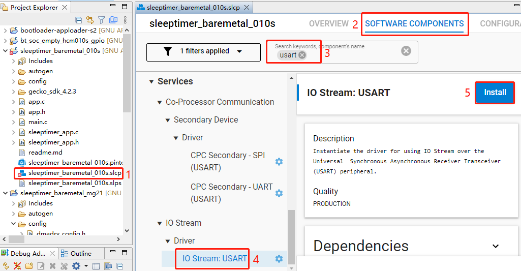
- In sleeptimer_baremetal_010s project, find and double-click sleeptimer_baremetal_010s.slcp to go to "sleeptimer_baremetal_010s" page. Select the "SOFTWARE COMPONENTS" tab and enter "usart" in the search box. Choose "IO Stream: USART" from the search results and then click "Install" to install the IO Stream: USART component.
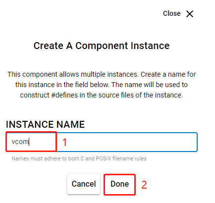
- After clicking "Install", the following interface will appear. Rename the component instance to "vcom" under "INSTANCE NAME" and then click "Done".
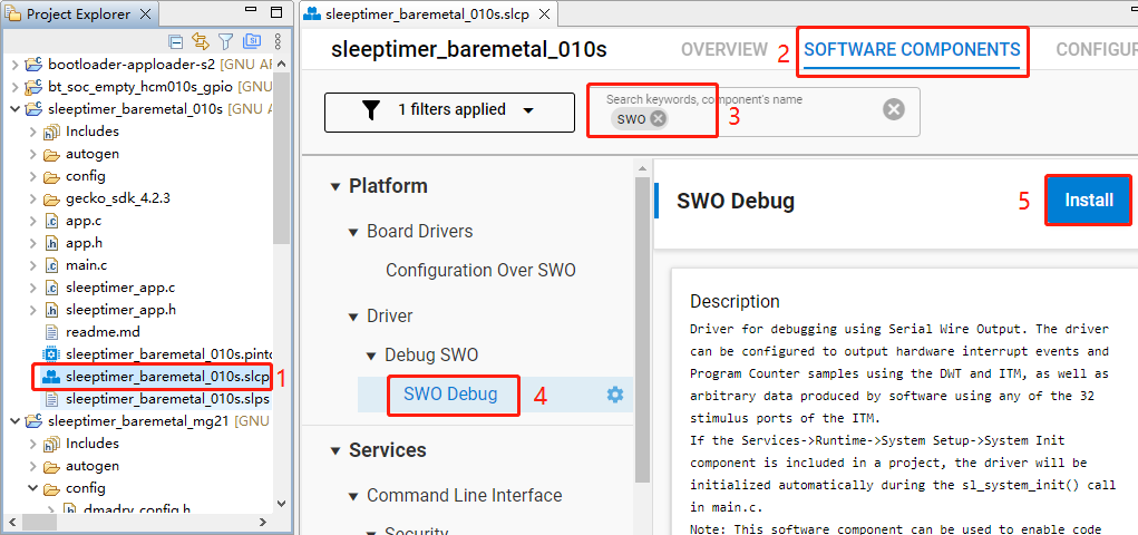
- Double-click sleeptimer_baremetal_010s.slcp to go to "sleeptimer_baremetal_010s" page. Select the "SOFTWARE COMPONENTS" tab and enter "SWO" in the search box. Choose "SWO Debug" from the search results and then click "Install" to install the SWO Debug component.
Configure the components that are not configured.
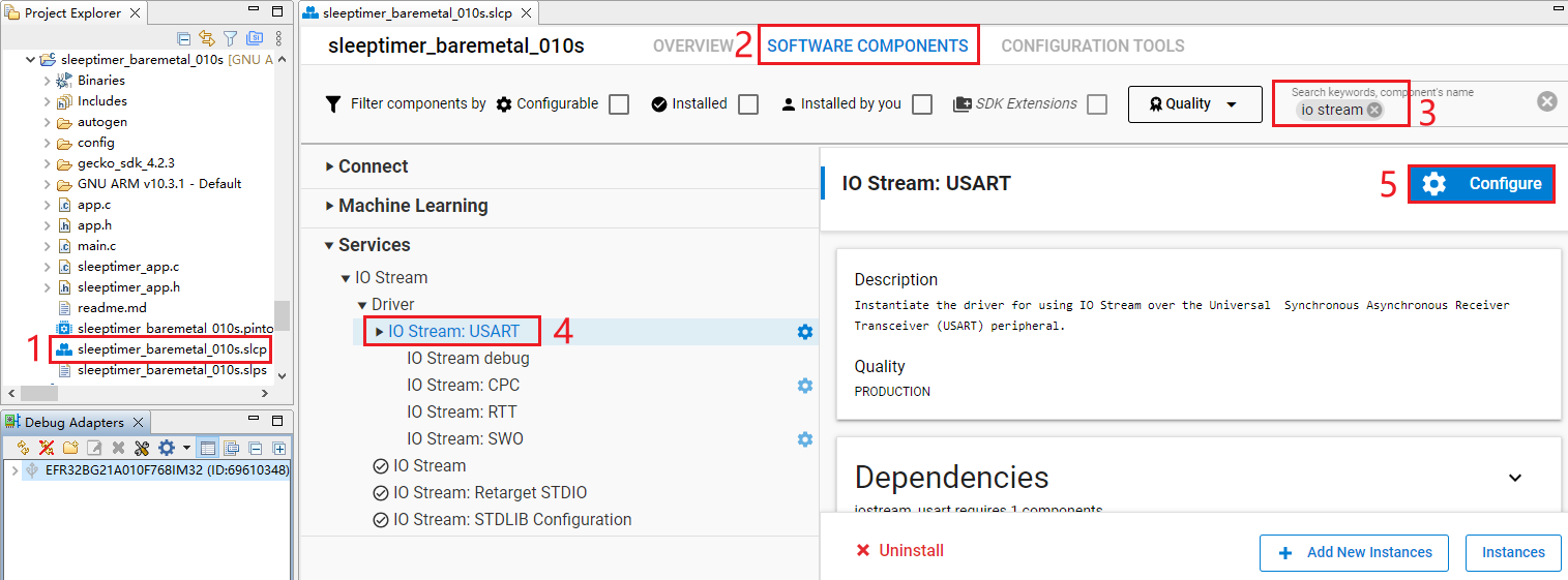
- Double-click sleeptimer_baremetal_010s.slcp to go to "sleeptimer_baremetal_010s" page. Select the "SOFTWARE COMPONENTS" tab and enter "io stream" in the search box. Choose "IO Stream: USART" from the search results and then click "Configure" to open the IO Stream: USART component configuration interface.
Configure the IO Stream: USART component as outlined in red below, then click "</> View Source".
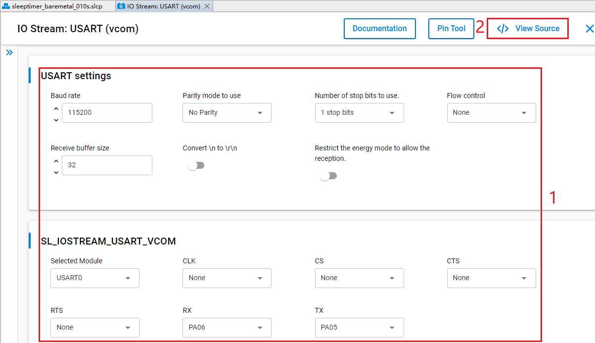
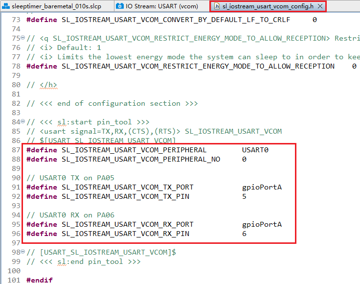
The sl_iostream_usart_vcom_config.h file shown in the following figure will pop up, and the code lines outlined in red will be generated after the IO Stream: USART component is configured.
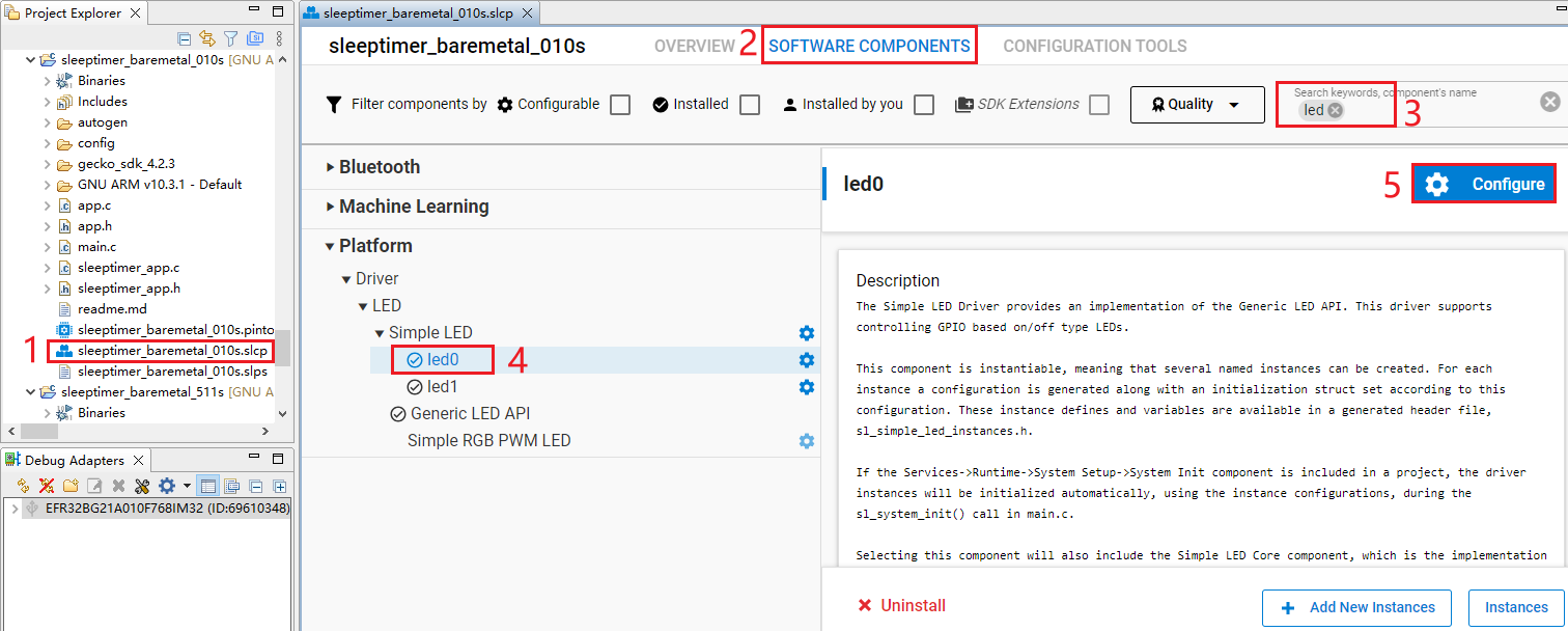
- Double-click sleeptimer_baremetal_010s.slcp to go to "sleeptimer_baremetal_010s" page. Select the "SOFTWARE COMPONENTS" tab and enter "led" in the search box. Choose "led0" from the search results and then click "Configure" to open the Simple LED (led0) component configuration interface.
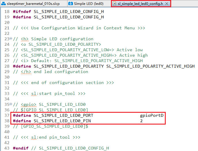
Configure the Simple LED (led0) component as outlined in red below and select PD02 as LED0 in this step. Then click "</> View Source".
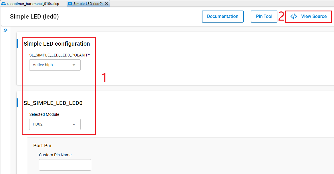
The sl_simple_led_led0_config.h file shown in the following figure will pop up, and the code lines outlined in red will be generated after the Simple LED (led0) component is configured.
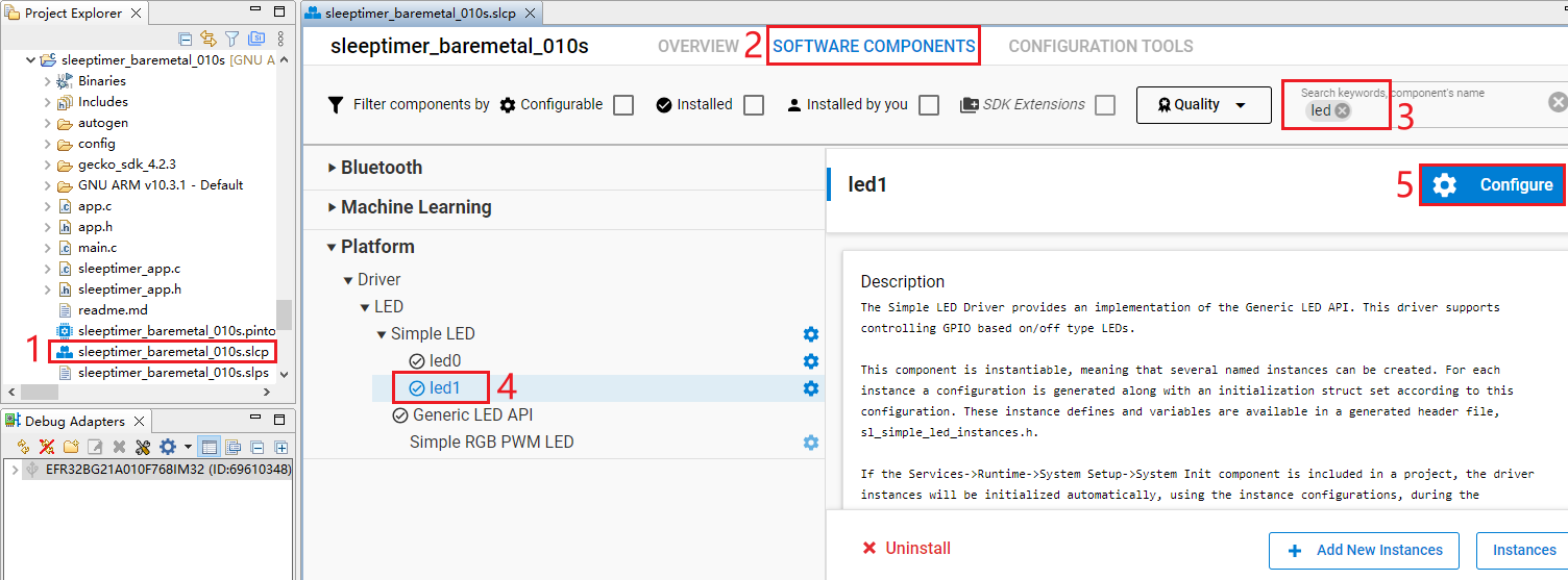
- Double-click sleeptimer_baremetal_010s.slcp to go to "sleeptimer_baremetal_010s" page. Select the "SOFTWARE COMPONENTS" tab and enter "led" in the search box. Choose "led1" from the search results and then click "Configure" to open the Simple LED (led1) component configuration interface.
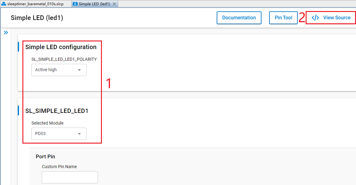
Configure the Simple LED (led1) component and select PD03 as LED1 as outlined in red below. Then click "</> View Source".
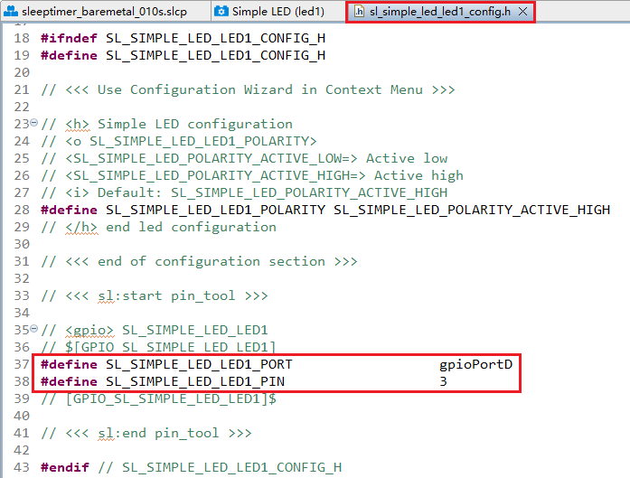
The sl_simple_led_led1_config.h file shown in the following figure will pop up, and the code lines outlined in red will be generated after the Simple LED (led1) component is configured.
The HCM010S-TE-B has only one reset button and no other button, so btn0 and btn1 should be removed. Perform the following operations to remove btn0 and btn1:
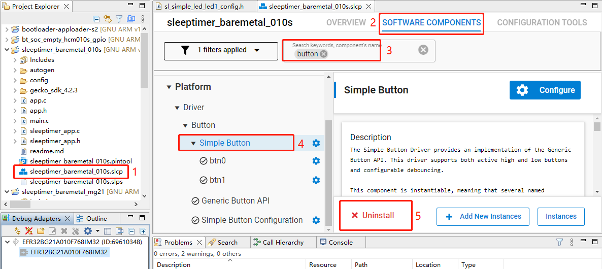
- Double-click sleeptimer_baremetal_010s.slcp to go to the "sleeptimer_baremetal_010s" interface. Select the "SOFTWARE COMPONENTS" tab and enter "button" in the search box. Choose "Simple Button" from the search results and then click "Uninstall".
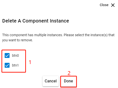
- The following interface appears after you click "Uninstall". Check "btn0" and "btn1" and then click "Done".
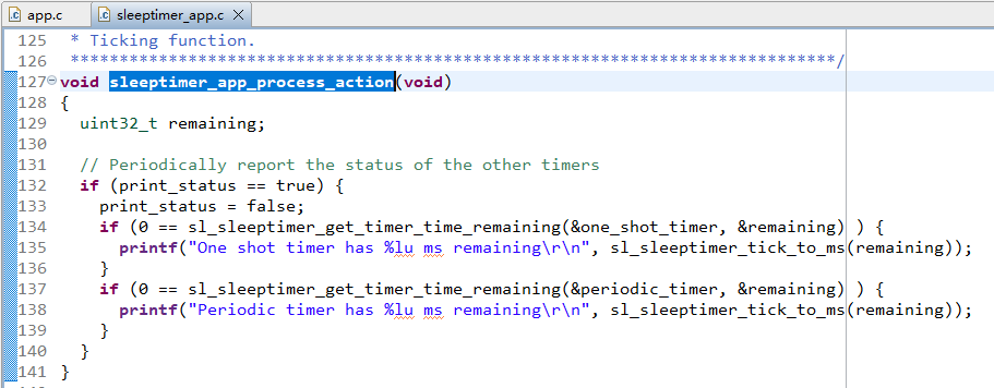
- In sleeptimer_baremetal_010s project, find and double-click sleeptimer_app.c to open it, and then delete sl_button_on_change() from it.
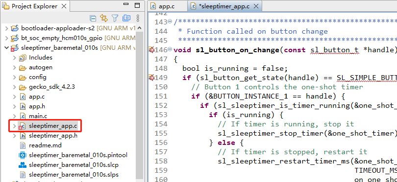
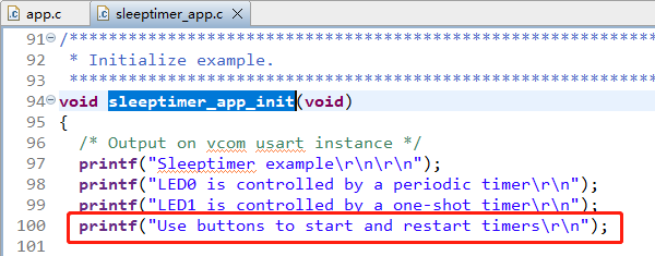
- Delete the code lines outlined in red from sleeptimer_app.c.
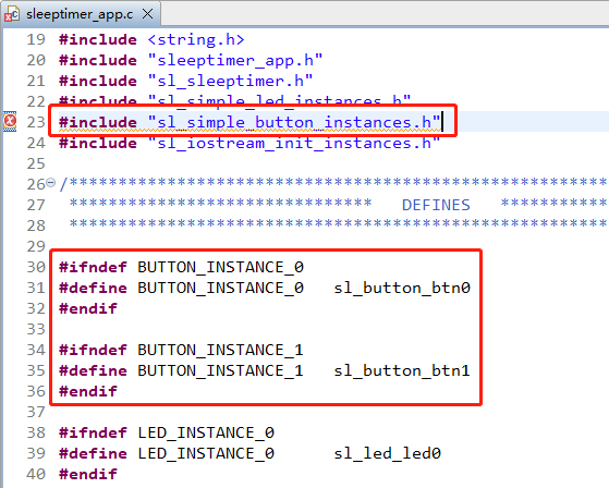
Program Description
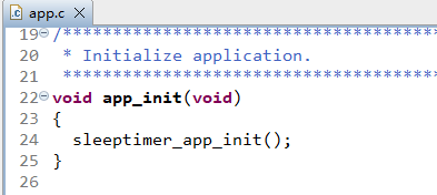
Application starts

Initialize the application through app_init().
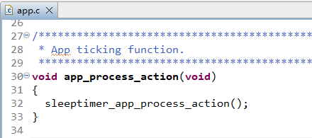
app_process_action() is executed repeatedly in a loop.
When the program starts, sleeptimer_app_init() performs actions such as log printing.
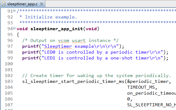
sleepertimer_app_process_action() prints the remaining time of the timer every second.
Bluetooth - Soc Empty
Soc Empty is a minimalistic project framework for Bluetooth application development, offering a standardized starting point for custom Bluetooth apps. The example projects in *Chapter 3.1.1* and *Chapter 3.1.2* can achieve specific functionalities, but the Soc Empty example project is just a basic communication structure. It serves as a template for standalone Bluetooth applications. The device automatically enters broadcast mode upon startup and resumes broadcasting immediately after disconnection. Developers need to add specific feature codes and integrate required components based on this framework.
This chapter uses the development of the bt_soc_empty_hcm010s_led application based on the Soc Empty as an example to demonstrate the application development process for implementing GPIO peripheral functionality.
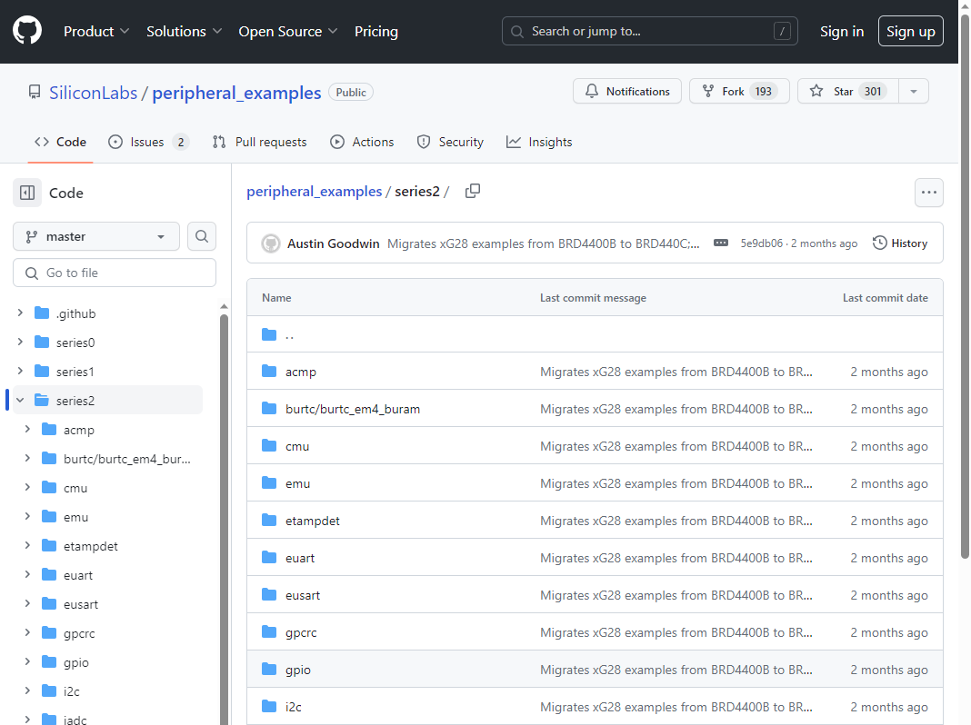
Examples of peripherals can be found in the following GitHub repository: https://github.com/SiliconLabs/peripheral_examples/tree/master/series2.
Import Example
- Copy the above GitHub repository link for the peripheral examples and open it in a web browser. The interface appears as shown below:
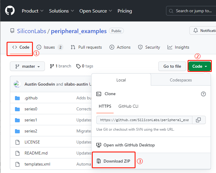
- Click "<> Code" > "Code" > "Download ZIP" to download the code resources.
Extract the downloaded peripheral_examples-master.zip and then import the required peripheral examples from the extracted resource package. For example, to import a GPIO peripheral example, perform the following steps:
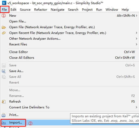
- In the Simplicity Studio tool interface, click "File" > "Import..." to go to the "Import Project" interface.
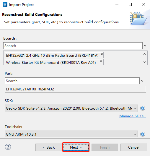
- Click "Browse..." to select the path of the extracted GPIO peripheral example. Choose the project outlined in red, and then click "[N]ext>".

Continue clicking "[N]ext>" until the project settings appear.
- Set the project name as shown in the figure below, and then click "[F]inish " to complete the example import process.
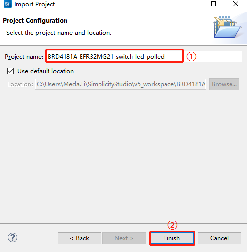
The imported example project is as follows:
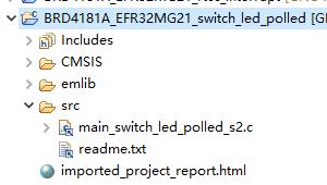
You can configure your own project based on the source files and other components of the imported project.
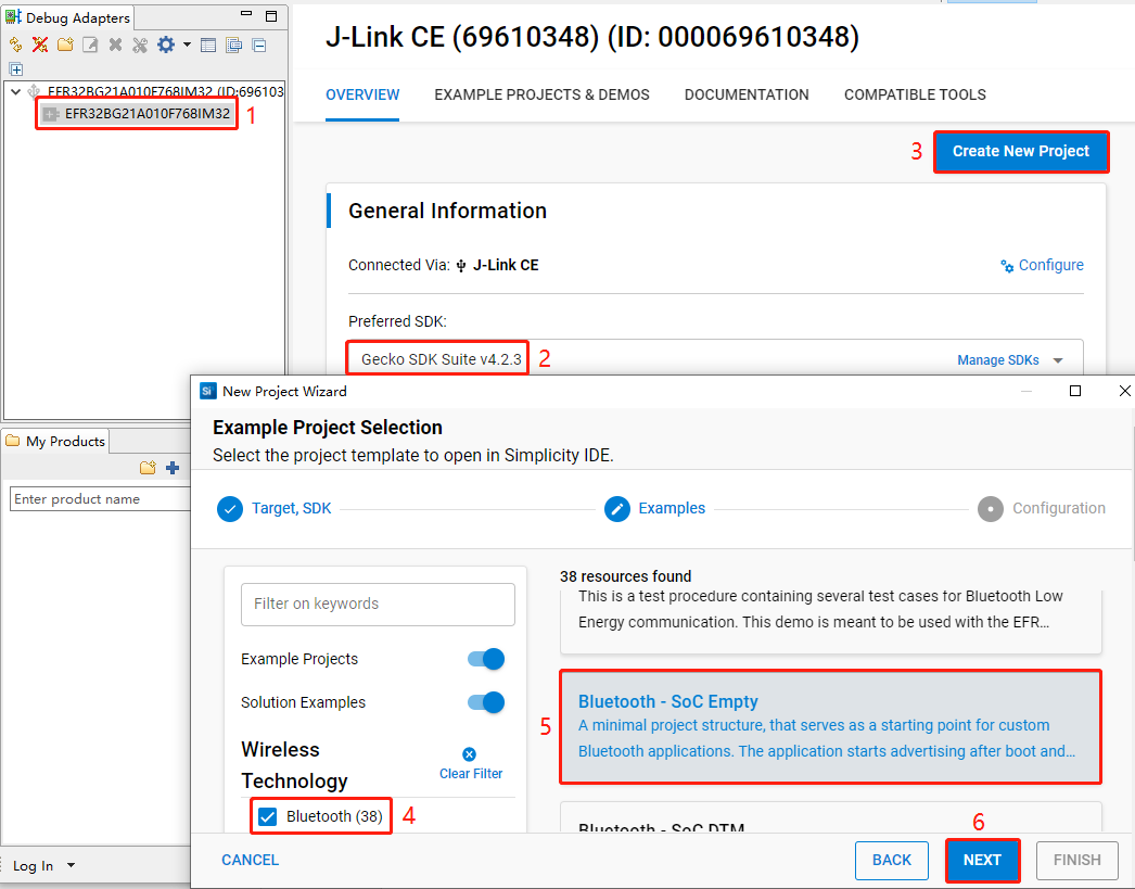
Create Project
Configure device by following *Steps 1* and *2 in Chapter 3.1.1.1*.
Select the device on the Simplicity Studio tool interface > Select Gecko SDK Suite v4.2.3 (that is, gecko_sdk-gsdk_4.2) > Click "Create New Project" > In the "New Project Wizard" window that pops up, follow the prompts to navigate to the "Example Project Selection" interface, and select the "Bluetooth" check box in the lower-left corner > Select "Bluetooth - Soc Empty" > Click "NEXT" to go to the "Project Configuration" interface.
- On the "Project Configuration" interface, set the project name as "bt_soc_empty_hcm010s_led" (the project path cannot be browsed and it will change based on the project name), select "Link sdk and copy project sources", and click "FINISH".
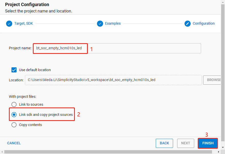
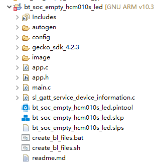
The created bt_soc_empty_hcm010s_led project is as follows. For details about the project directory structure, see *Table 4*.
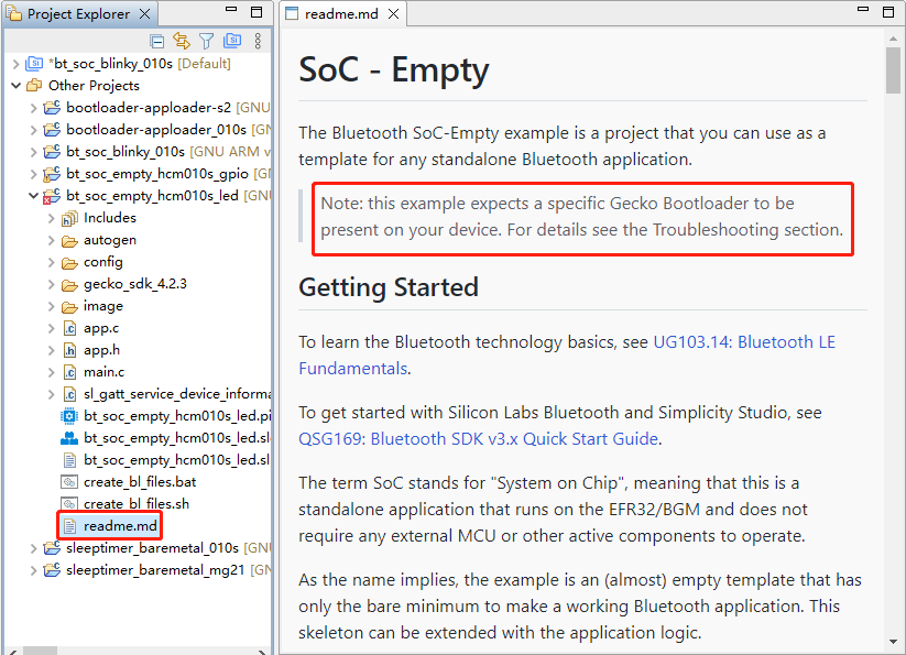
After the project is created, the readme.md file of bt_soc_empty_hcm010s_led is displayed, as shown in the following figure:
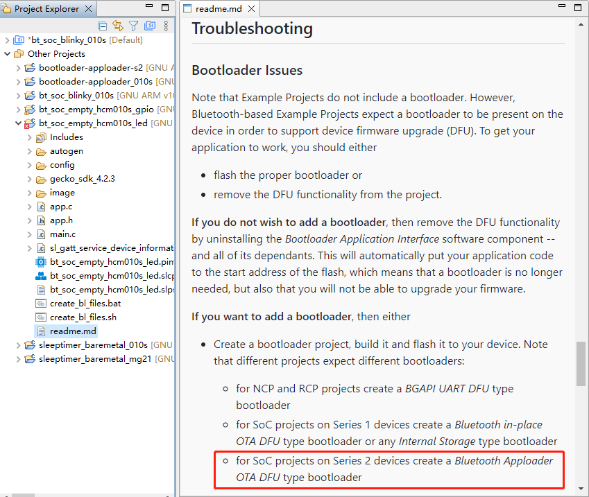
- Create a bootloader project. According to the readme.md file, the bt_soc_empty_hcm010s_led project requires a bootloader. As shown in the Troubleshooting section in the following figure, the required bootloader type is Bluetooth Apploader OTA DFU type bootloader. You can refer to the *Step 5* in *Chapter 3.1.1.1* to create a bootloader project. If you have already created a bootloader project, you do not need to create it again.
Configure Project
Find and install the required components.
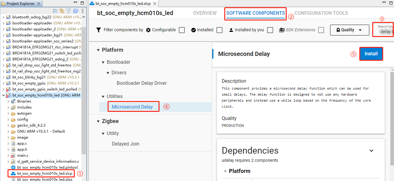
- In bt_soc_empty_hcm010s_led project, find and double-click bt_soc_empty_hcm010s_led.slcp to go to "bt_soc_empty_hcm010s_led" page. Select the "SOFTWARE COMPONENTS" tab and enter "delay" in the search box. Choose "Microsecond Delay" from the search results and then click "Install" to install the Microsecond Delay component.
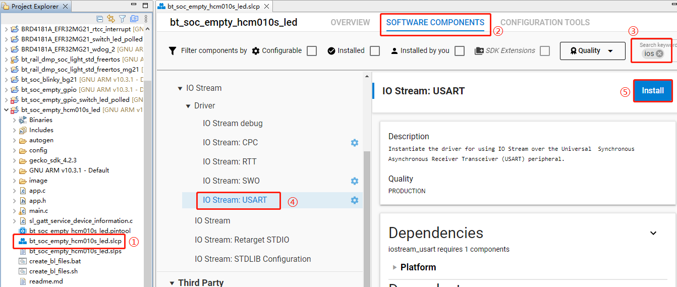
- Double-click bt_soc_empty_hcm010s_led.slcp to go to "bt_soc_empty_hcm010s_led" page. Select the "SOFTWARE COMPONENTS" tab and enter "ios" in the search box. Choose "IO Stream: USART" from the search results and then click "Install" to install the IO Stream: USART component.
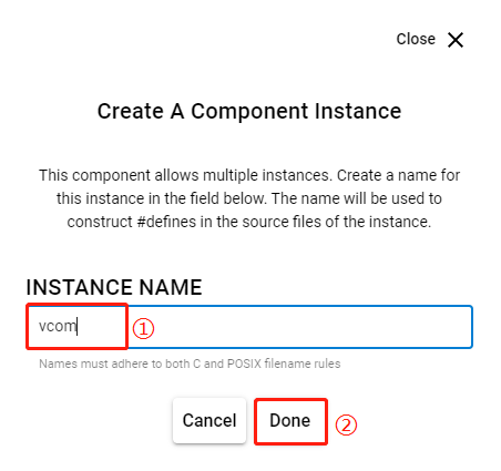
- After clicking "Install", the following interface will appear. Rename the component instance to "vcom" under "INSTANCE NAME" and then click "Done".
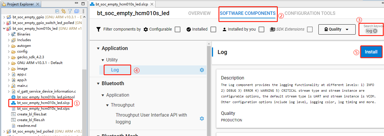
- Double-click bt_soc_empty_hcm010s_led.slcp to go to "bt_soc_empty_hcm010s_led" page. Select the "SOFTWARE COMPONENTS" tab and enter "log" in the search box. Choose "Log" from the search results and then click "Install" to install the Log component.
- Configure the components that are not configured.
Double-click bt_soc_empty_hcm010s_led.slcp to go to "bt_soc_empty_hcm010s_led" page. Select the "SOFTWARE COMPONENTS" tab and enter "io stream" in the search box. Choose "IO Stream: USART" from the search results and then click "Configure" to open the IO Stream: USART component configuration interface.
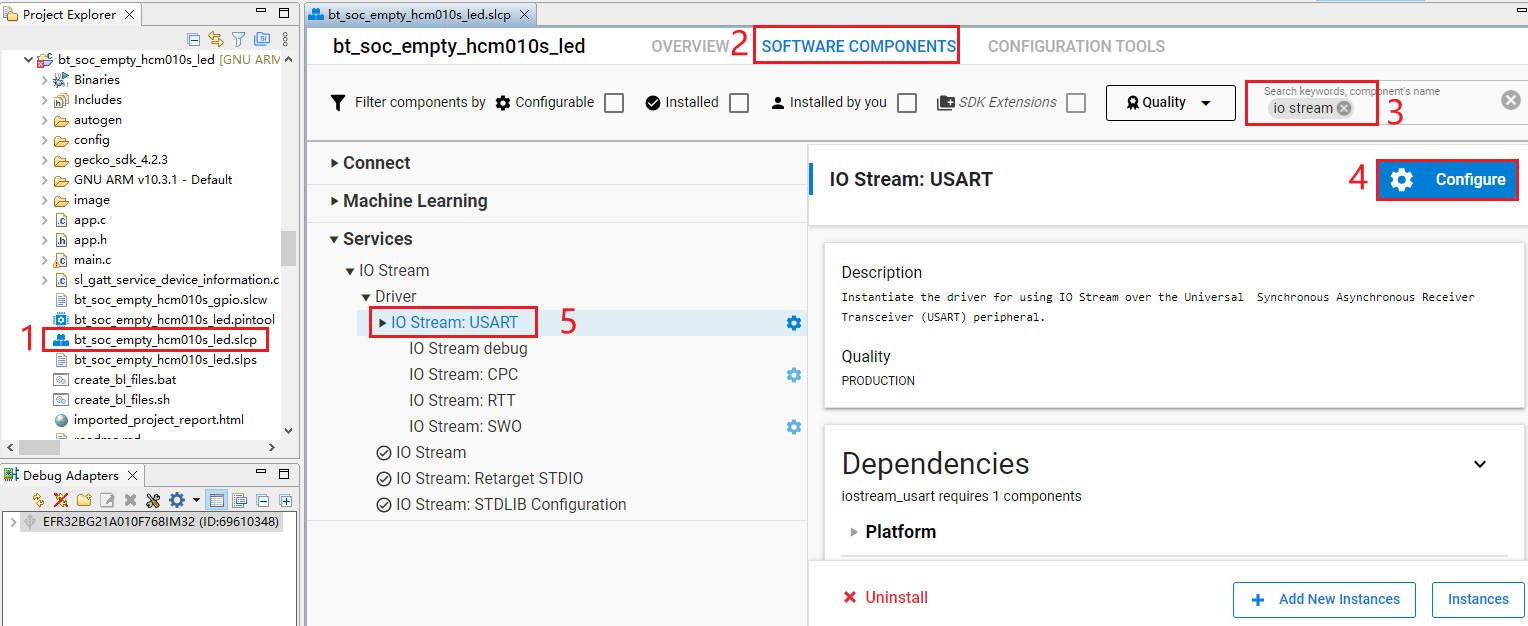
Configure the IO Stream: USART component as outlined in red below, then click "</> View Source".
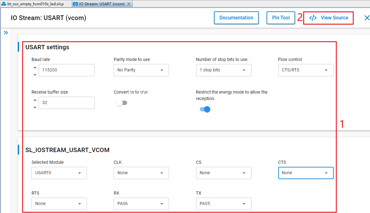
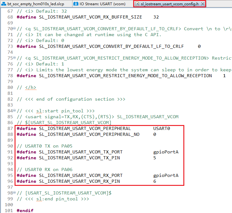
The sl_iostream_usart_vcom_config.h file shown in the following figure will pop up, and the code lines outlined in red will be generated after the IO Stream: USART component is configured.
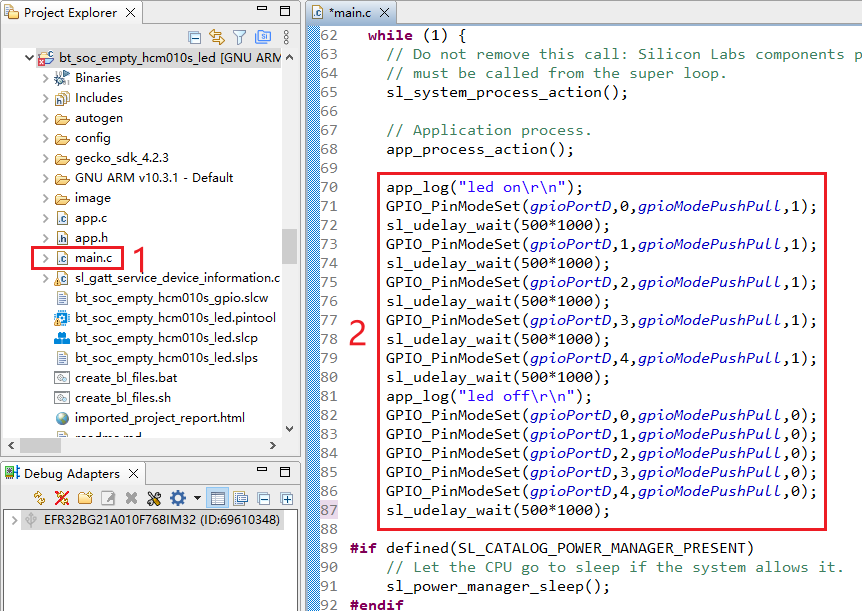
- Find the main.c file in the project and double-click main.c to open it. And then add the code lines outlined in red to the file.
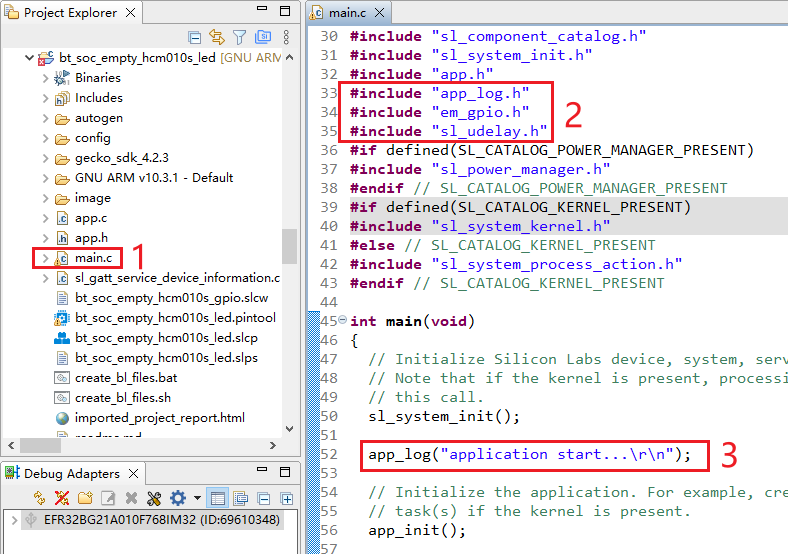
Add the code lines outlined in red to the while(1) part in main.c:
Program Description
LED on/off
Application starts
Reset Log
Application Development Example for HCM511S/HCM511S-E
This chapter outlines how to develop SoC Blinky, Sleeptimer Bare-metal and Soc Empty applications based on HCM511S-TE-B.
Table 5: Pin Mapping Relationship for HCM511S and HCM511S-E Modules
| HCM511S Pin No. | HCM511S-E Pin No. | Pin Name | Chip Pin Name |
|---|---|---|---|
| - | 1 | GND | GND |
| - | 2 | ANT_BT | RF2G4 |
| 1 | 3 | GND | GND |
| 2 | 4 | VBAT | VBAT |
| 3 | 5 | SWCLK | PA01 |
| 4 | 6 | SWDIO | PA02 |
| 5 | 7 | RESET_N | RESET_N |
| 6 | 8 | GPIO2 | PA03 |
| 7 | 9 | GPIO3 | PA04 |
| 8 | 10 | GND | GND |
| 9 | 11 | GND | GND |
| 10 | 12 | GPIO1 | PA00 |
| 11 | 13 | GPIO6 | PB00 |
| 12 | 14 | GPIO7 | PB01 |
| 13 | 15 | GPIO8 | PB02 |
| 14 | 16 | GPIO14 | PD01 |
| 15 | 17 | GPIO13 | PD00 |
| 16 | 18 | GPIO9 | PC02 |
| 17 | 19 | GPIO10 | PC03 |
| 18 | 20 | GPIO11 | PC04 |
| 19 | 21 | GPIO12 | PC05 |
| 20 | 22 | GPIO4 | PA05 |
| 21 | 23 | GPIO5 | PA06 |
| 22 | 24 | USART_TXD | PC00 |
| 23 | 25 | USART_RXD | PC01 |
| 24 | 26 | RESERVED | RESERVED |
NOTE
See *documents [7]* and *[8]* for detailed pin information.
Bluetooth - SoC Blinky
This chapter details the development workflow of the "bt_soc_blinky_511s" SoC Blinky application, which enables Bluetooth-based control of the LED on/off states for the HCM511S-TE-B. The LED states are not directly indicated by physical lights on the HCM511S-TE-B but are instead reflected through the voltage levels of their corresponding GPIO pins: a low voltage level indicates the LED is off, while a high voltage level confirms the LED is illuminated.
Create Project
- In the "Debug Adapters" section of the Simplicity Studio main interface, locate the J-Link debugger (such as J-Link CE (69610348) in the figure below). Right-click the J-Link debugger and select "Device configuration...".
- In the pop-up J-Link CE (69610348) configuration interface, enter and select the corresponding chip model in the "Target part" text box, and then click "OK". (The chip model varies depending on the used module model. For details, contact Quectel Technical Support.)
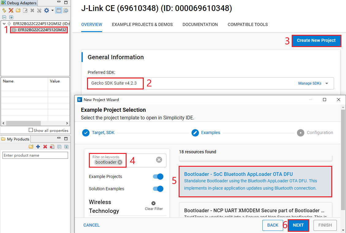
- Select the device on the Simplicity Studio tool interface > Select Gecko SDK Suite v4.2.3 (that is, gecko_sdk-gsdk_4.2) > Click "Create New Project" > In the "New Project Wizard" window that pops up, follow the prompts to navigate to the "Example Project Selection" interface, and select the "Bluetooth" check box in the lower-left corner > Select "Bluetooth - SoC Blinky" > Click "NEXT" to go to the "Project Configuration" interface.
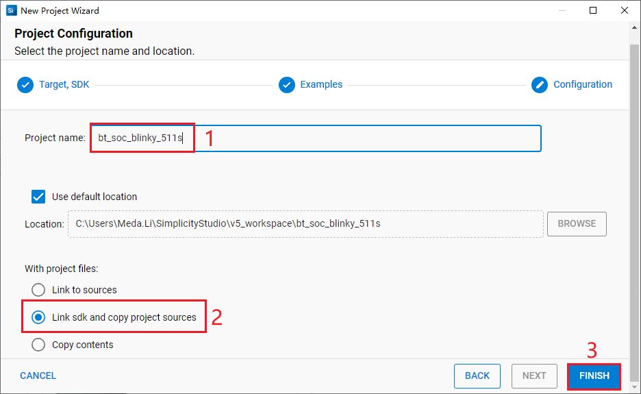
- On the "Project Configuration" interface, set the project name as "bt_soc_blinky_511s", select "Link sdk and copy project sources" (the project path cannot be browsed and it will change based on the project name), and click "FINISH".
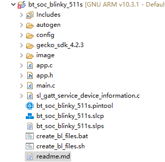
The created bt_soc_blinky_511s project is as follows. For details about the project directory structure, see *Table 4*.
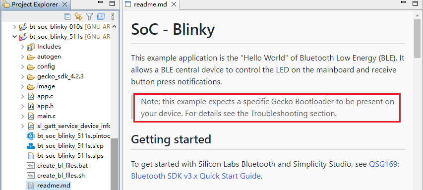
After the project is created, the readme.md file of bt_soc_blinky_511s is displayed as shown in the following figure.
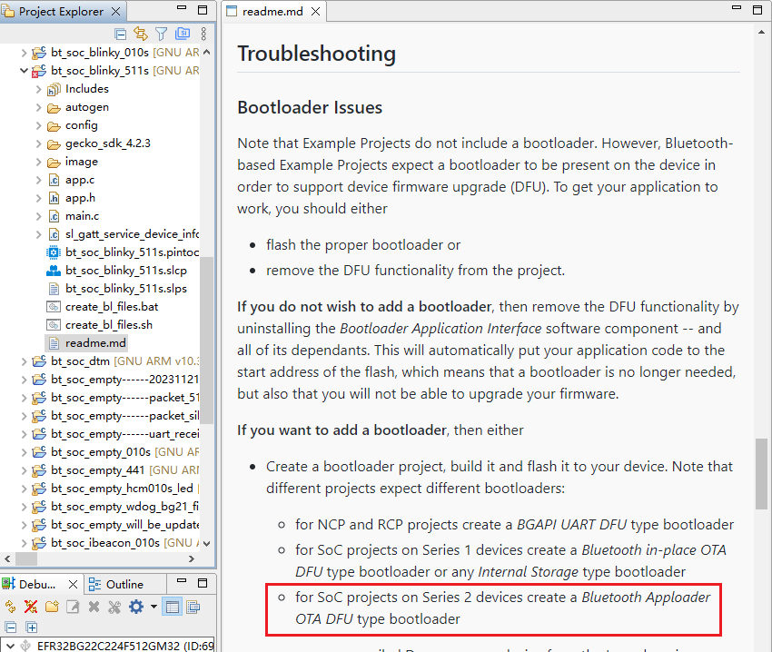
- Create a bootloader project. According to the readme.md file, the bt_soc_blinky_010s project requires a bootloader. As shown in the Troubleshooting section in the following figure, the required bootloader type is Bluetooth Apploader OTA DFU type bootloader.
- Click "Launcher" in the upper-right corner of the tool interface to return to the initial interface (to switch back to the development environment click "Simplicity IDE").
- Perform the following steps to choose the bootloader: Select the device > Choose Gecko SDK Suite v4.2.3 > Click "Create New Project" > Enter "Bootloader" in the "Filter on keywords" search box on the left-side of "Example Project Selection" interface > Select "Bootloader - Soc Bluetooth AppLoader OTA DFU" from the search result > Click "Next".
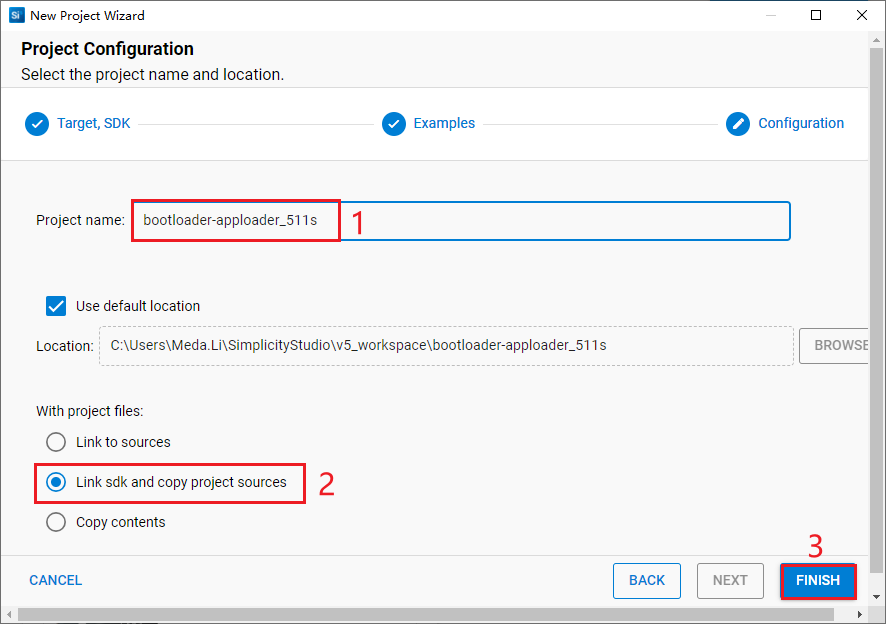
- On the "Project Configuration" interface, set the project name as "bootloader-apploader_511s", select "Link sdk and copy project sources" (the project path cannot be browsed and it will change based on the project name), and click "FINISH".
The created bootloader-apploader_511s project is as follows:
Configure Project
- Find and install the required component.
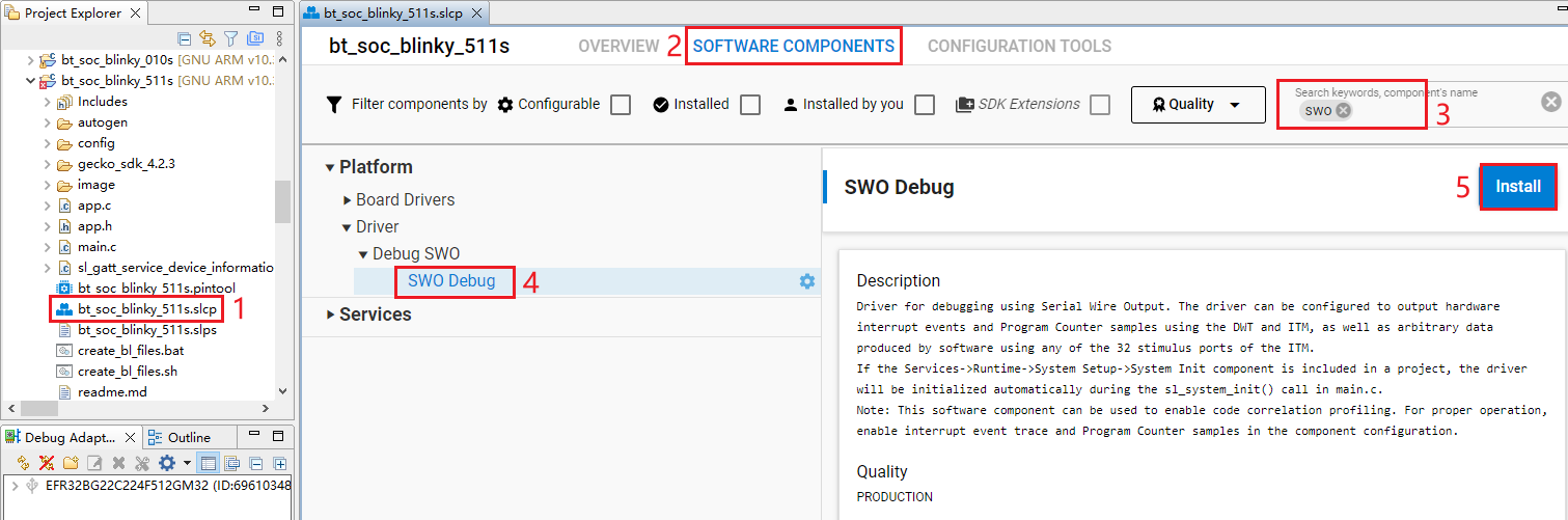
In bt_soc_blinky_511s project, find and double-click bt_soc_blinky_511s.slcp to go to "bt_soc_blinky_511s" page. Select the "SOFTWARE COMPONENTS" tab and enter "SWO" in the search box. Choose "SWO Debug" from the search results and then click "Install" to install the SWO Debug component.
Configure the components that are not configured.
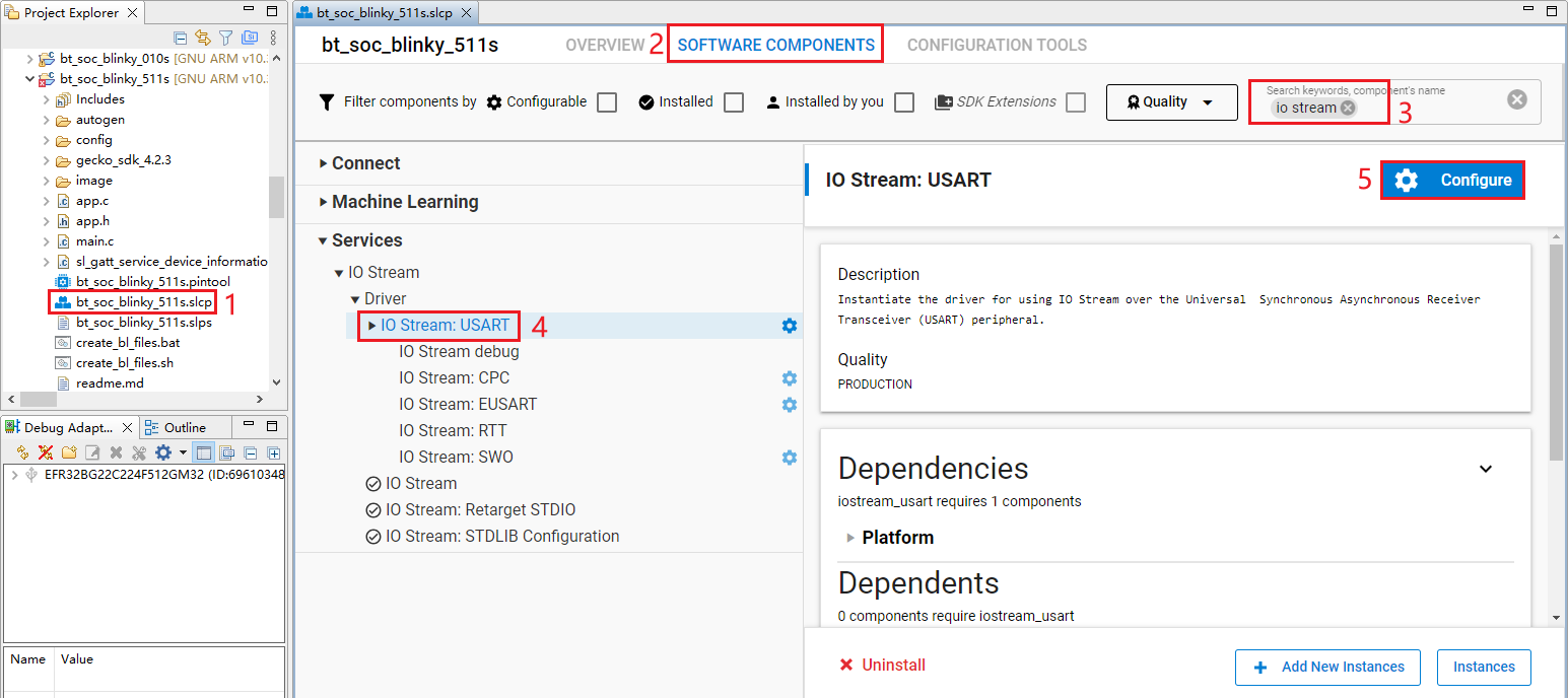
- Double-click bt_soc_blinky_511s.slcp to go to "bt_soc_blinky_511s" page. Select the "SOFTWARE COMPONENTS" tab and enter "io stream" in the search box. Choose "IO Stream: USART" from the search results and then click "Configure" to open the IO Stream: USART component configuration interface.
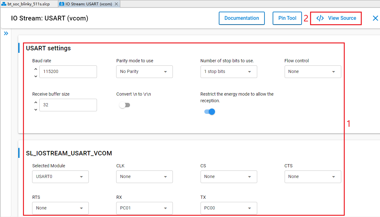
Configure the IO Stream: USART component as outlined in red below, then click "</> View Source".
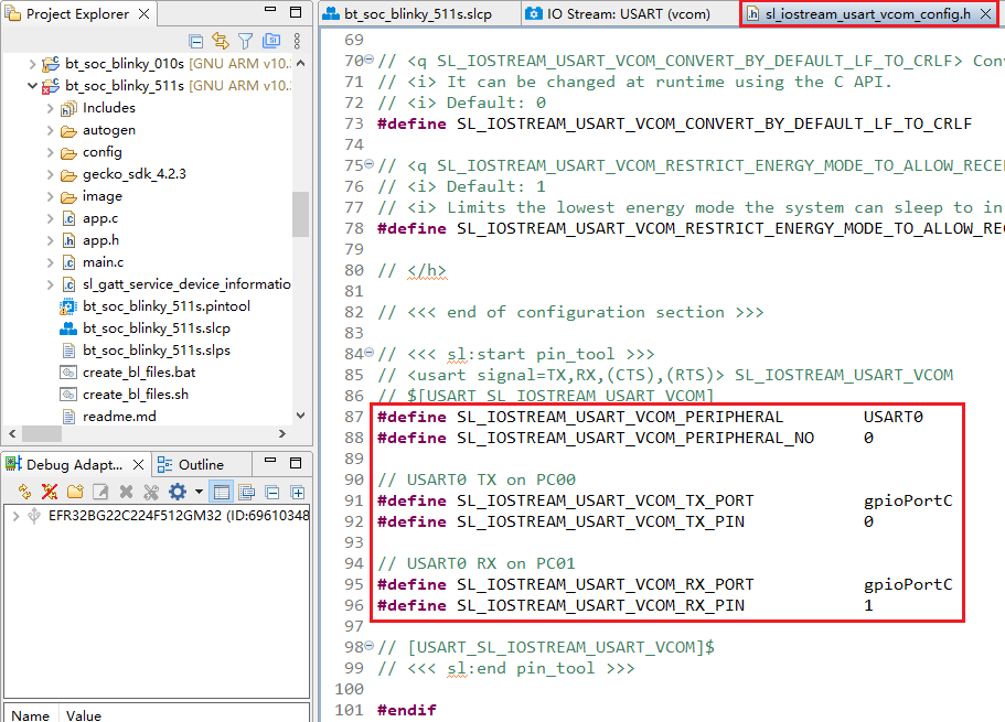
The sl_iostream_usart_vcom_config.h file shown in the following figure will pop up, and the code lines outlined in red will be generated after the IO Stream: USART component is configured.
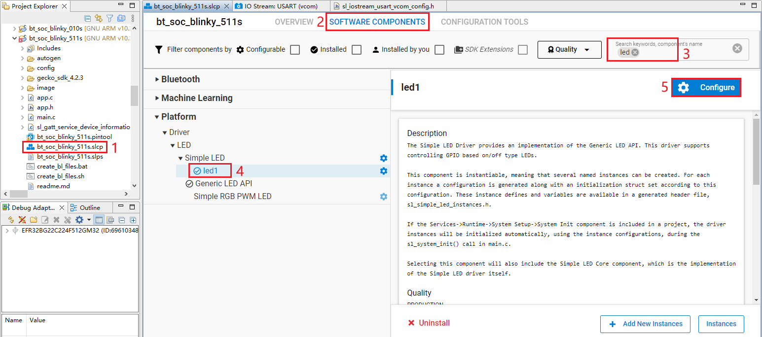
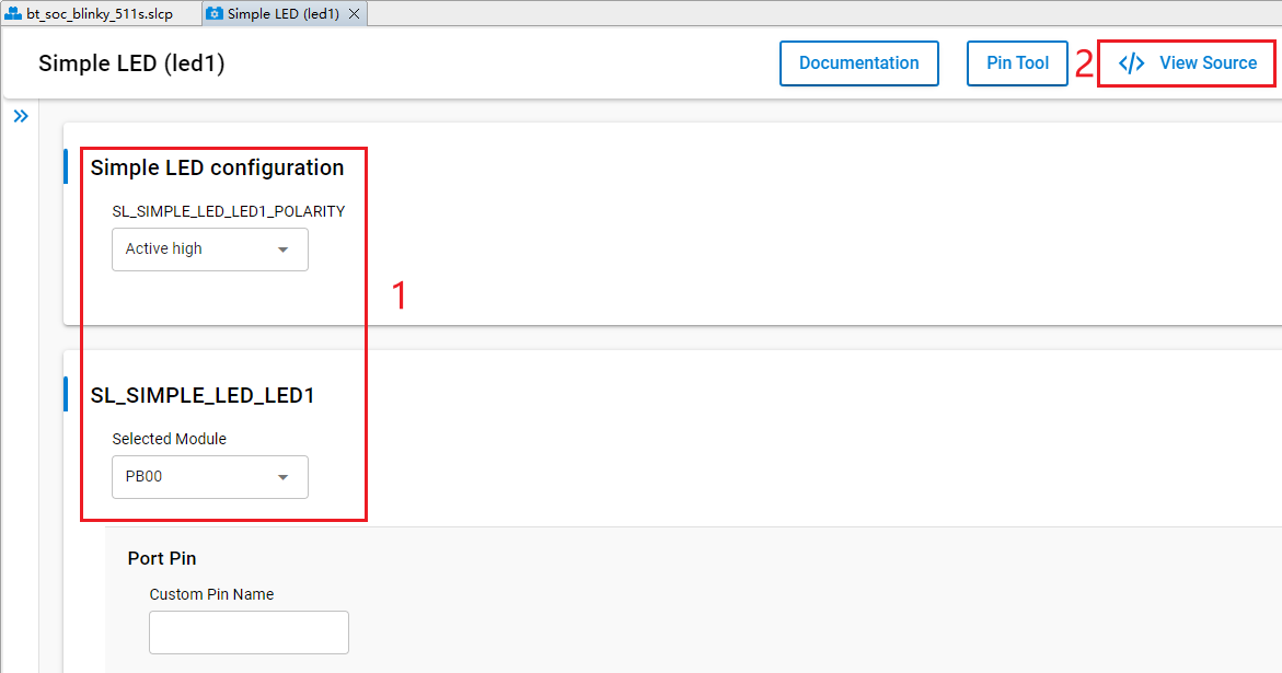
- Double-click bt_soc_blinky_511s.slcp to go to "bt_soc_blinky_511s" page. Select the "SOFTWARE COMPONENTS" tab and enter "led" in the search box. Choose "led1" from the search results and then click "Configure" to open the Simple LED (led1) component configuration interface.
Configure the Simple LED (led1) component as outlined in red below. The LED1 pin can be configured to any unused GPIO pin, taking PB00 as an example. Then click "</> View Source".
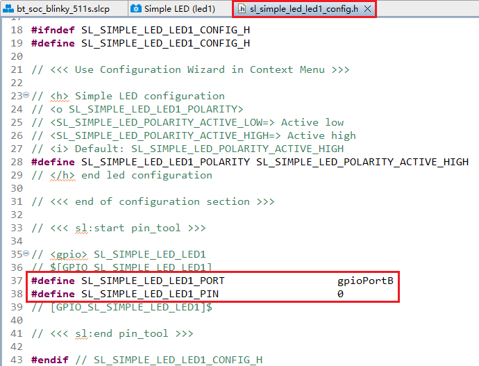
The sl_simple_led_led1_config.h file shown in the following figure will appear, and the code lines outlined in red will be generated after the Simple LED (led1) component is configured.
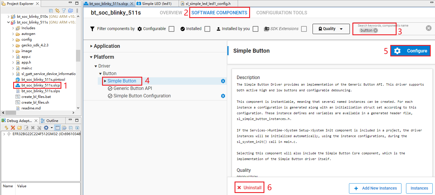
The HCM511S-TE-B has only one reset button and no other button, so btn0 should be removed. Perform the following operations to remove btn0:
- Double-click bt_soc_blinky_511s.slcp to go to the "bt_soc_blinky_511s" interface. Select the "SOFTWARE COMPONENTS" tab and enter "button" in the search box. Choose "Simple Button" from the search results, and then click "Uninstall".
- The following interface appears after you click "Uninstall". Select "btn0", and then click "Done".
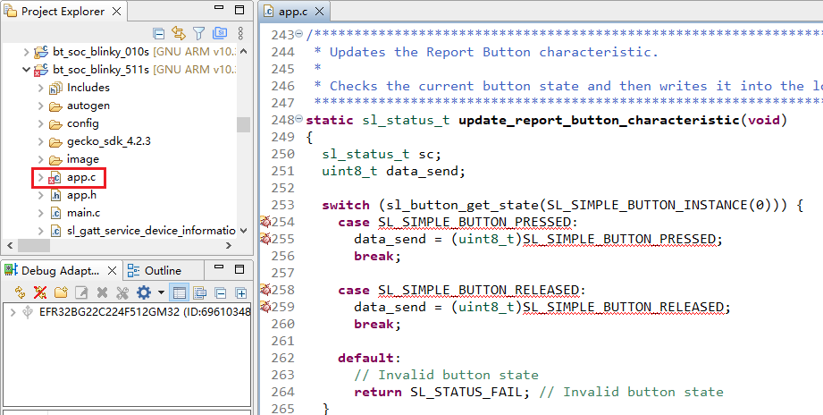
- In bt_soc_blinky_511s project, find and double-click app.c to open it, and then delete update_report_button_characteristic().
- Delete sl_button_on_change() from app.c.
- Add the code lines outlined in red to the proper location (above the "Toggle LED" part) in app.c file.
- Delete the code lines outlined in red from app.c.
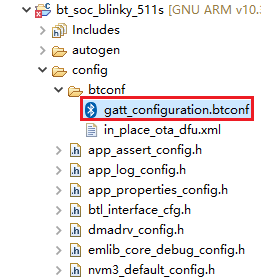
- Complete additional configurations.
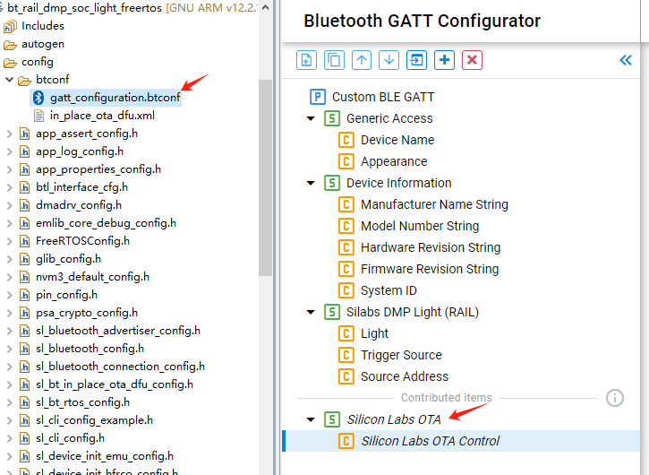
To view or modify the GATT configuration file gatt_configuration.btconf, expand the target project > config > btconf, and then double-click gatt_configuration.btconf to open it.
Program Description


Platform - Sleeptimer Bare-metal
This chapter describes the application development process using the development of Sleeptimer Bare-metal application named sleeptimer_baremetal_511s in a bare-metal environment as an example.
The example application creates two periodic timers and one single-shot timer. The single-shot timer and one periodic timer switch the state of the two LED lights (on/off), and the other periodic timer prints the remaining time for the two timers mentioned above. You can view the related logs in the debugging window of a serial port tool.
The LED states are not directly indicated by physical lights on the HCM511S-TE-B but are instead reflected through the voltage levels of their corresponding GPIO pins: a low voltage level indicates the LED is off, while a high voltage level confirms the LED is illuminated.
Create Project
Configure device by following *Steps 1* and *2 in Chapter 3.2.1.1*.
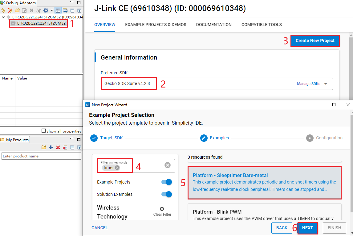
Select the device on the Simplicity Studio tool interface > Select Gecko SDK Suite v4.2.3 (that is, gecko_sdk-gsdk_4.2) > Click "Create New Project" > In the "New Project Wizard" window that pops up, follow the prompts to navigate to the "Example Project Selection" interface, and enter "timer" in the "Filter on keywords" search box on the left > Select "Platform - Sleeptimer Bare-metal" > Click "NEXT" to go to the "Project Configuration" interface.
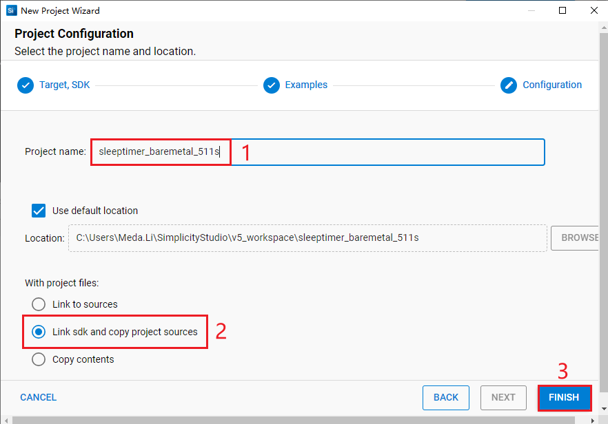
- On the "Project Configuration" interface, set the project name as "sleeptimer_baremetal_511s" (the project path cannot be browsed and it will change based on the project name), select "Link sdk and copy project sources", and click "FINISH".
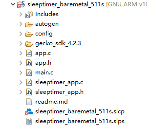
The created sleeptimer_baremetal_511s project is as follows. For details about the project directory structure, see *Table 4*.
Configure Project
Find and install the required components.
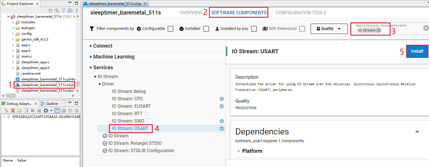
- In sleeptimer_baremetal_511 project, find and double-click sleeptimer_baremetal_511s.slcp to go to "sleeptimer_baremetal_511s" page. Select the "SOFTWARE COMPONENTS" tab and enter "io stream" in the search box. Choose "IO Stream: USART" from the search results and then click "Install" to install the IO Stream: USART component.
- After clicking "Install" as shown in the figure above, the following interface will appear. Rename the component instance to "vcom" under "INSTANCE NAME" and then click "Done".
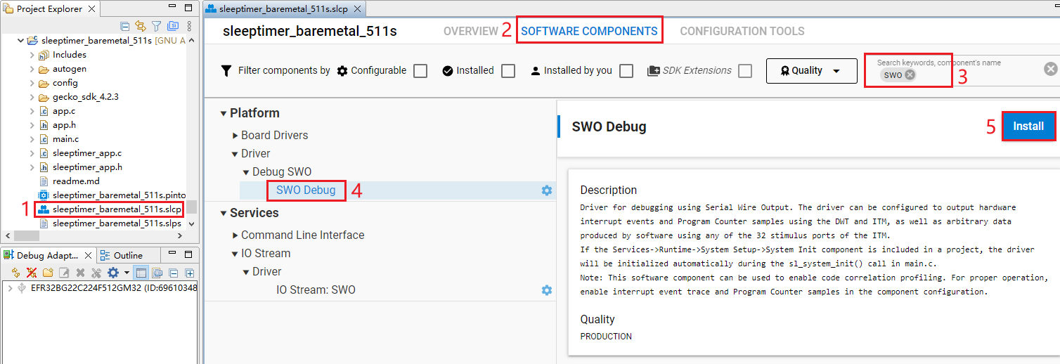
- Double-click sleeptimer_baremetal_511s.slcp to go to "sleeptimer_baremetal_511s" page. Select the "SOFTWARE COMPONENTS" tab and enter "SWO" in the search box. Choose "SWO Debug" from the search results and then click "Install" to install the SWO Debug component.
Configure the components that are not configured.
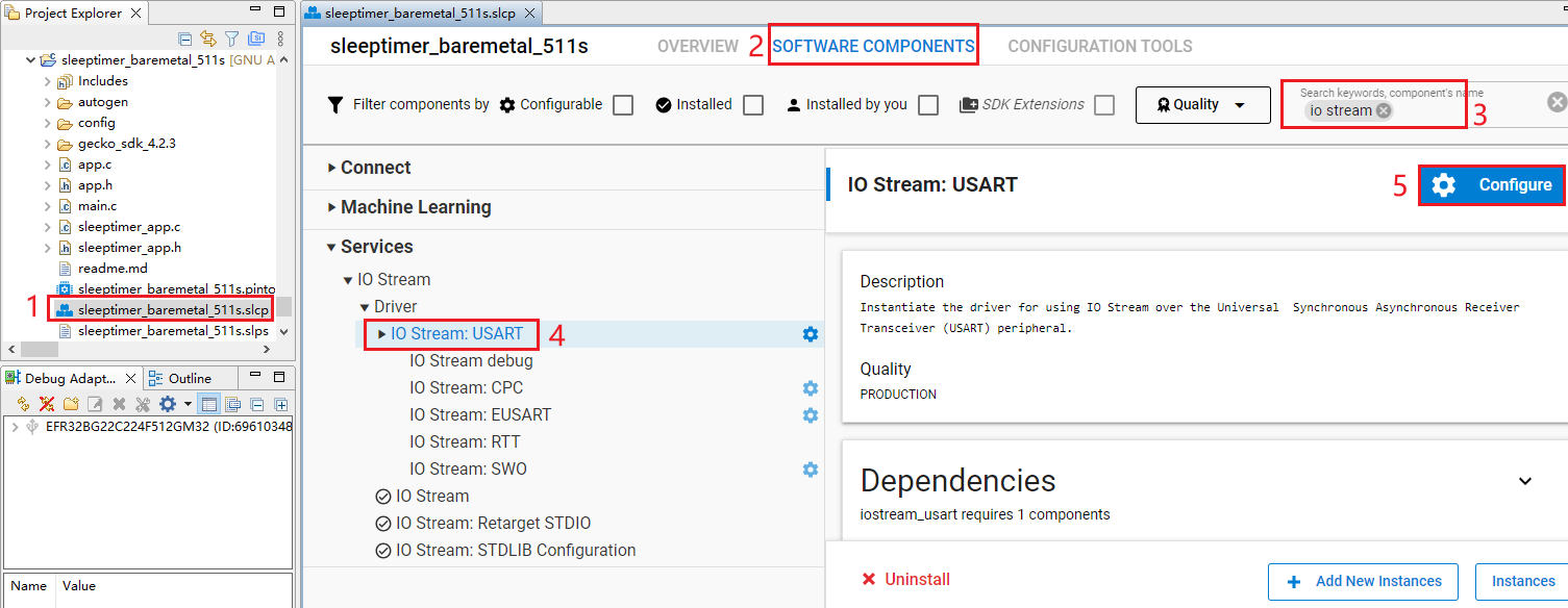
- Double-click sleeptimer_baremetal_511s.slc to go to "sleeptimer_baremetal_511s" page. Select the "SOFTWARE COMPONENTS" tab and enter "io stream" in the search box. Choose "IO Stream: USART" from the search results and then click "Configure" to open the IO Stream: USART component configuration interface.
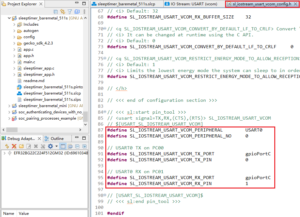
Configure the IO Stream: USART component as outlined in red below, then click "</> View Source".
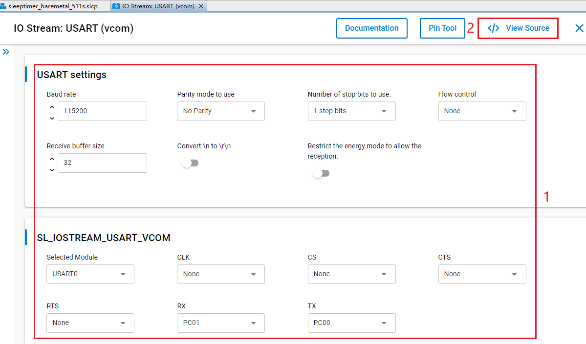
The sl_iostream_usart_vcom_config.h file shown in the following figure will pop up, and the code lines outlined in red will be generated after the IO Stream: USART component is configured.
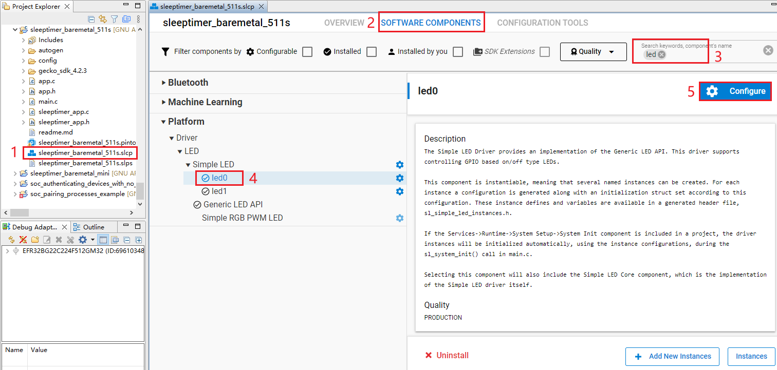
- Double-click sleeptimer_baremetal_511s.slcp to go to "sleeptimer_baremetal_511s" page. Select the "SOFTWARE COMPONENTS" tab and enter "led" in the search box. Choose "led0" from the search results and then click "Configure" to open the Simple LED (led0) component configuration interface.
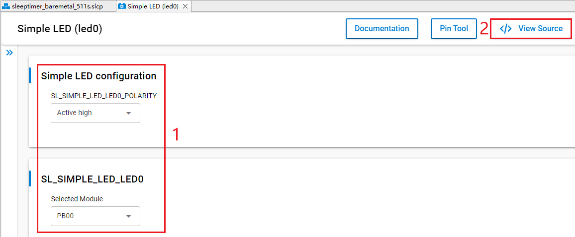
Configure the Simple LED (led0) component as outlined in red below. The LED0 pin can be configured to any unused GPIO pin, taking PB00 as an example. Then click "</> View Source".
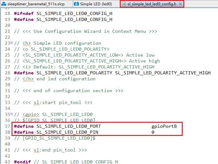
The sl_simple_led_led0_config.h file shown in the following figure will pop up, and the code lines outlined in red will be generated after the Simple LED (led0) component is configured.
- Double-click sleeptimer_baremetal_511s.slcp to go to "sleeptimer_baremetal_511s" page. Select the "SOFTWARE COMPONENTS" tab and enter "led" in the search box. Choose "led1" from the search results and then click "Configure" to open the Simple LED (led1) component configuration interface.
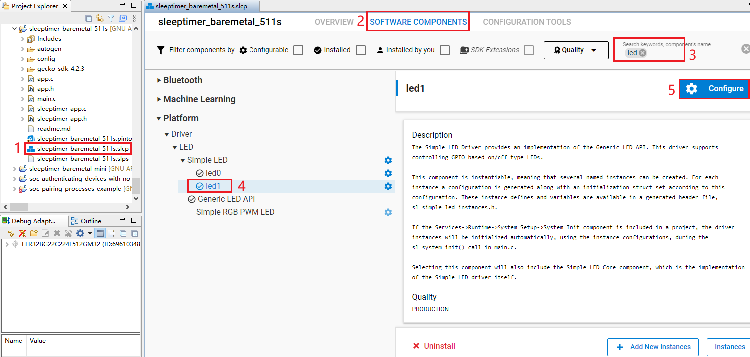
Configure the Simple LED (led1) component as outlined in red below. The LED1 pin can be configured to any unused GPIO pin, taking PB01 as an example. Then click "</> View Source".
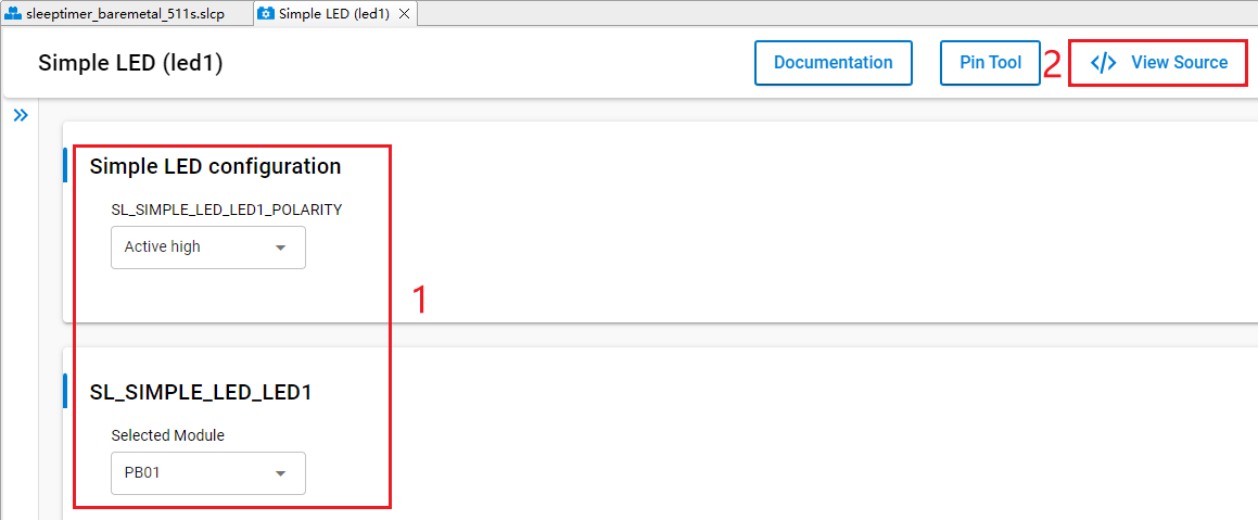
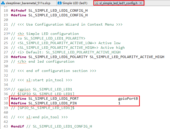
The sl_simple_led_led1_config.h file shown in the following figure will pop up, and the code lines outlined in red will be generated after the Simple LED (led1) component is configured.
The HCM511S-TE-B has only one reset button and no other button, so btn0 and btn1 should be removed. Perform the following operations to remove btn0:
- Double-click sleeptimer_baremetal_511s.slcp to go to the "sleeptimer_baremetal_511s" interface. Select the "SOFTWARE COMPONENTS" tab and enter "button" in the search box. Choose "Simple Button" from the search results and then click "Uninstall".
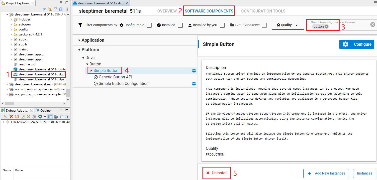
- The following interface appears after you click "Uninstall". Check "btn0" and "btn1" and then click "Done".
- Find the sleeptimer_app.c in sleeptimer_baremetal_511s project. Double-click sleeptimer_app.c to open it, and then delete sl_button_on_change().
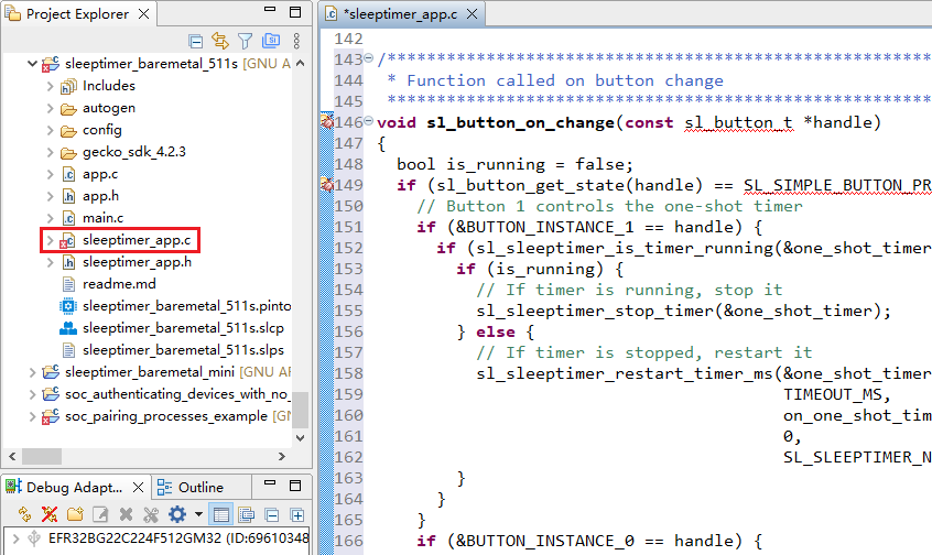
- Delete the code line outlined in red from sleeptimer_app.c.
Program Description
Application starts
Initialize the application through app_init().
app_process_action() is executed repeatedly in a loop.
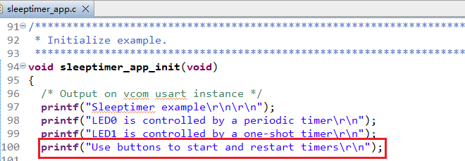
When the program starts, sleeptimer_app_init() performs actions such as log printing.
sleepertimer_app_process_action() prints the remaining time of the timer every second.
Bluetooth - Soc Empty
Soc Empty is a minimalistic project framework for Bluetooth application development, offering a standardized starting point for custom Bluetooth apps. The example projects in *Chapter 3.2.1* and *Chapter 3.2.2* can achieve specific functionalities, but the Soc Empty example project is just a basic communication structure. It serves as a template for standalone Bluetooth applications. The device automatically enters broadcast mode upon startup and resumes broadcasting immediately after disconnection. Developers need to add specific feature codes and integrate required components based on this framework.
This chapter uses the development of the bt_soc_empty_hcm511s_led application based on the Soc Empty as an example to demonstrate the application development process for implementing GPIO peripheral functionality.
Examples of peripherals can be found in the following GitHub repository: https://github.com/SiliconLabs/peripheral_examples/tree/master/series2.
Import Example
Follow the steps in *Chapter 3.1.3.1* to import the examples. You can configure your own project based on the source files and other contents of the imported project.
Create Project
Configure device by following *Steps 1* and *2 in Chapter 3.2.1.1*.
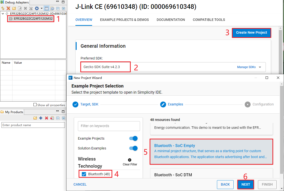
Select the device on the Simplicity Studio tool interface > Select Gecko SDK Suite v4.2.3 (that is, gecko_sdk-gsdk_4.2) > Click "Create New Project" > In the "New Project Wizard" window that pops up, follow the prompts to navigate to the "Example Project Selection" interface, and select the "Bluetooth" check box in the lower-left corner > Select "Bluetooth - Soc Empty" > Click "NEXT" to go to the "Project Configuration" interface.
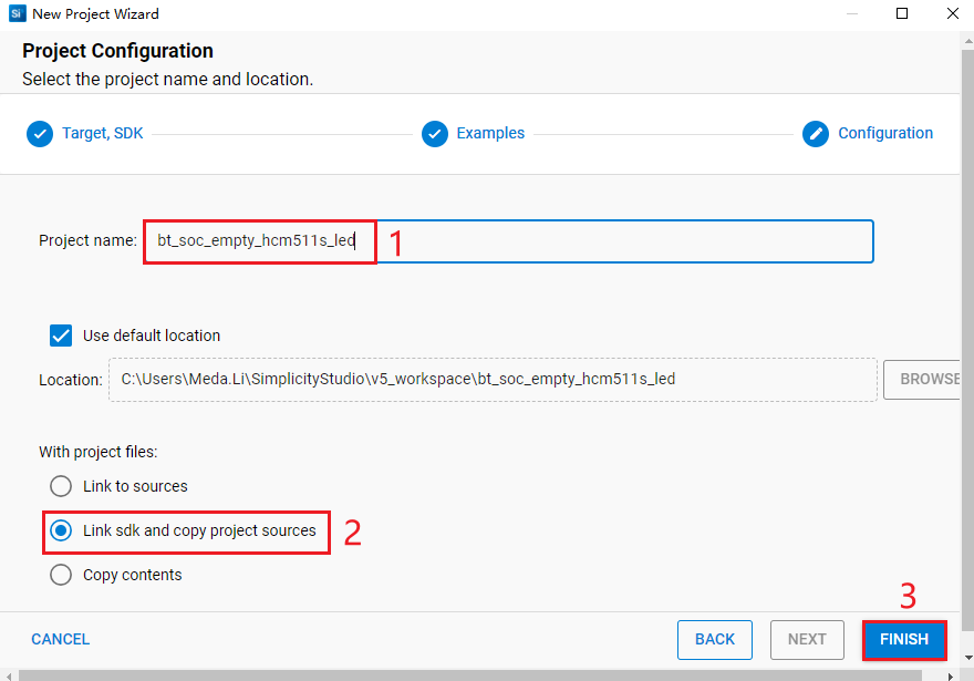
- On the "Project Configuration" interface, set the project name as "bt_soc_empty_hcm511s_led" (the project path cannot be browsed and it will change based on the project name), select "Link sdk and copy project sources", and click "FINISH".
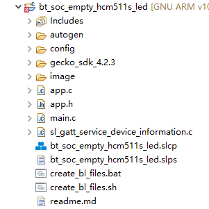
The created bt_soc_empty_hcm511s_led project is as follows. For details about the project directory structure, see *Table 4*.
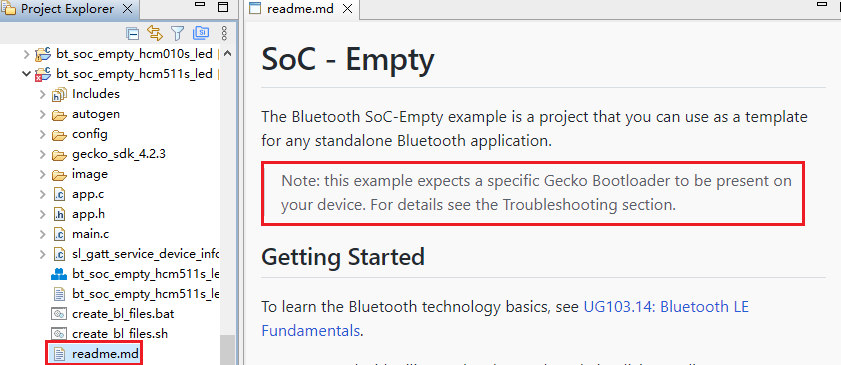
After the project is created, the readme.md file of bt_soc_empty_hcm511s_led is displayed, as shown in the following figure:
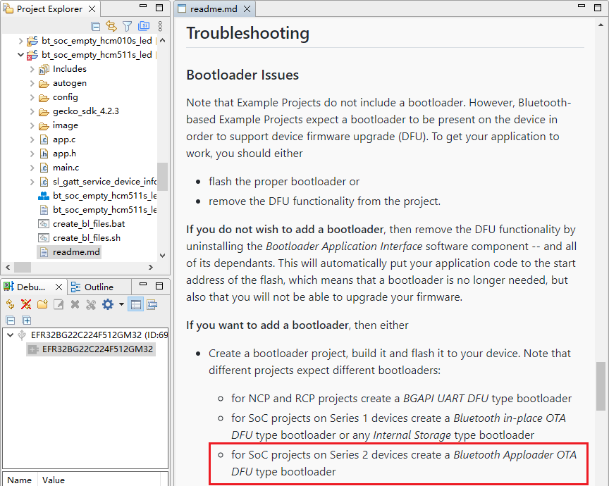
- Create a bootloader project. According to the readme.md file, the bt_soc_empty_hcm511s_led project requires a bootloader. As shown in the Troubleshooting section in the following figure, the required bootloader type is Bluetooth Apploader OTA DFU type bootloader. You can refer to the *Step 5* in *Chapter 3.2.1.1* to create a bootloader project. If you have already created a bootloader project, you do not need to create it again.
Configure Project
Find and install the required components.
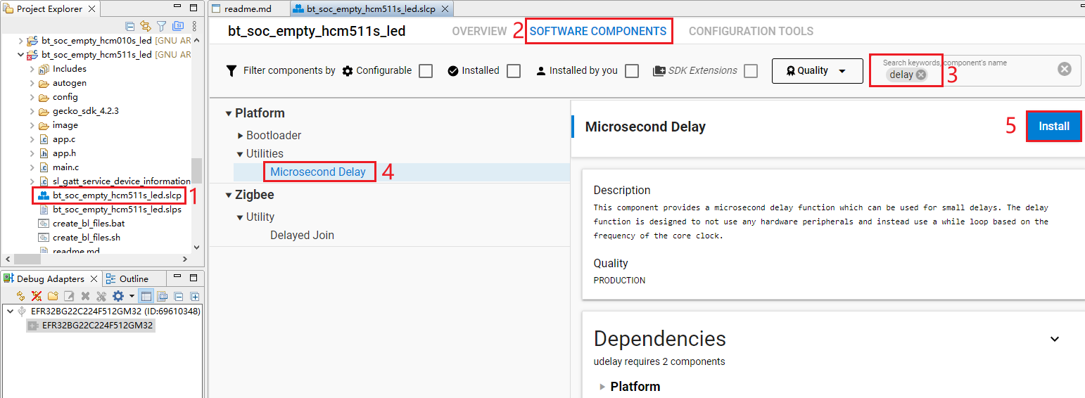
- In bt_soc_empty_hcm511s_led project, find and double-click bt_soc_empty_hcm511s_led.slcp to go to "bt_soc_empty_hcm511s_led" page. Select the "SOFTWARE COMPONENTS" tab and enter "delay" in the search box. Choose "Microsecond Delay" from the search results and then click "Install" to install the Microsecond Delay component.
- Double-click bt_soc_empty_hcm511s_led.slcp to go to "bt_soc_empty_hcm511s_led" page. Select the "SOFTWARE COMPONENTS" tab and enter "io stream" in the search box. Choose "IO Stream: USART" from the search results and then click "Install" to install the IO Stream: USART component.
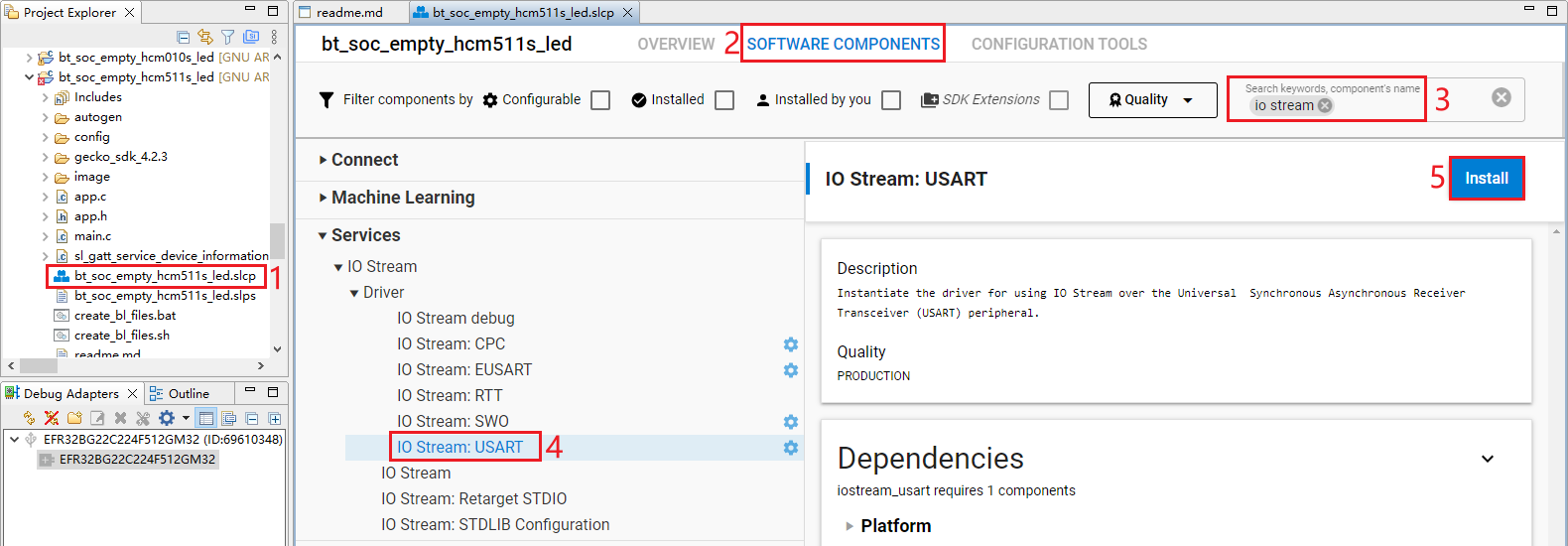
- After clicking "Install" as shown in the figure above, the following interface will appear. Rename the component instance to "vcom" under "INSTANCE NAME" and then click "Done".

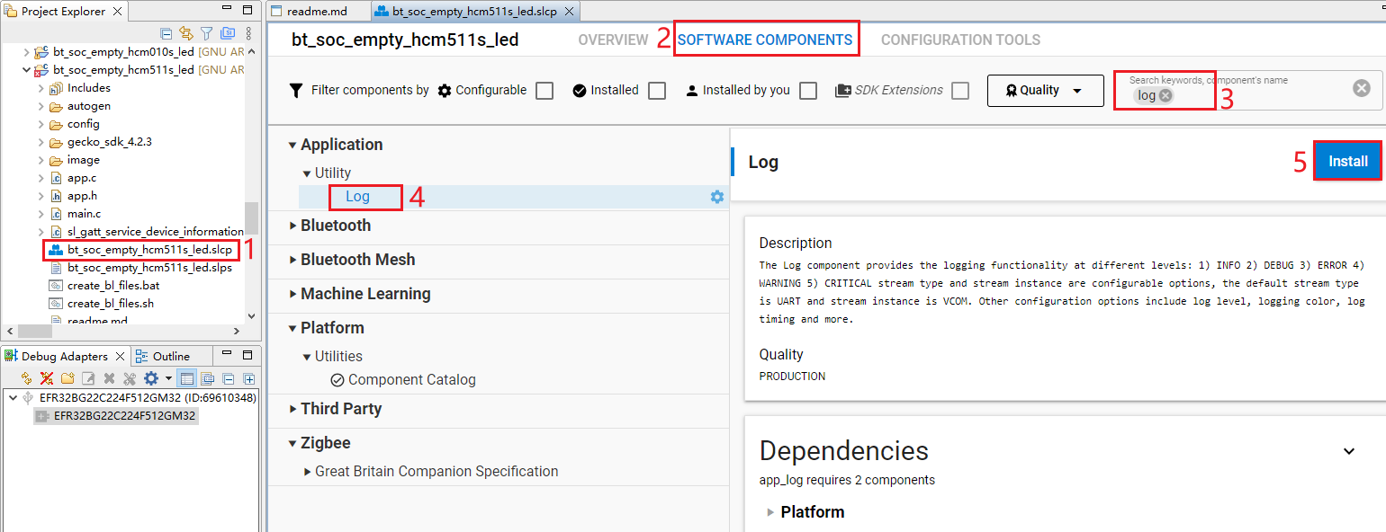
- Double-click bt_soc_empty_hcm511s_led.slcp to go to "bt_soc_empty_hcm511s_led" page. Select the "SOFTWARE COMPONENTS" tab and enter "log" in the search box. Choose "Log" from the search results and then click "Install" to install the Log component.
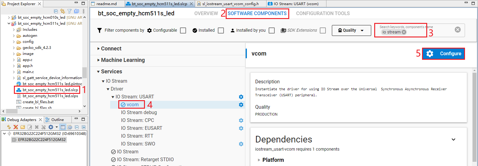
- Configure the components that are not configured.
Double-click bt_soc_empty_hcm511s_led.slcp to go to "bt_soc_empty_hcm511s_led" page. Select the "SOFTWARE COMPONENTS" tab and enter "io stream" in the search box. Choose "IO Stream: USART" from the search results and then click "Configure" to open the IO Stream: USART component configuration interface.
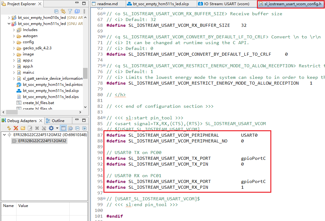
Configure the IO Stream: USART component as outlined in red below, then click "</> View Source".
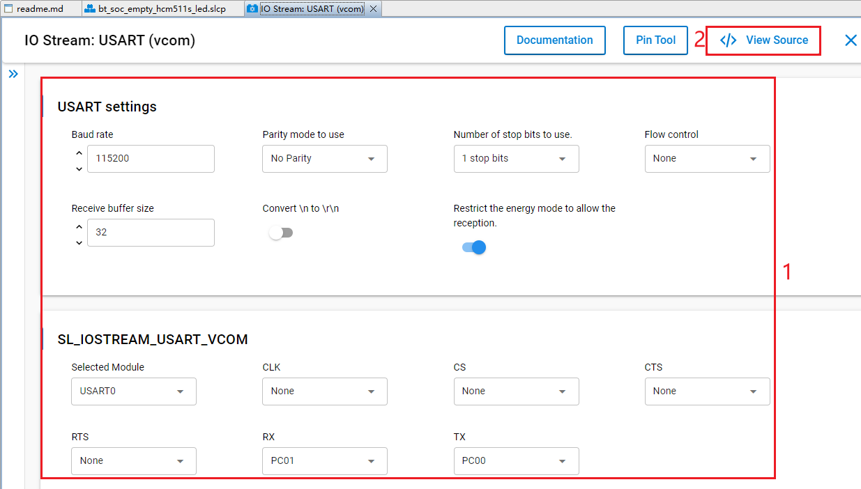
The sl_iostream_usart_vcom_config.h file shown in the following figure will pop up, and the code lines outlined in red will be generated after the IO Stream: USART component is configured.
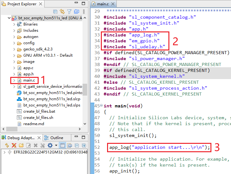
- Find the main.c in the project and double-click main.c to open it. And then add the code lines outlined in red to the file.
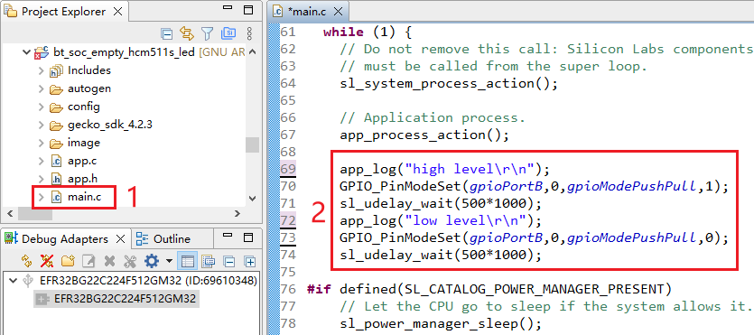
Add the code lines outlined in red to the while(1) part in main.c:
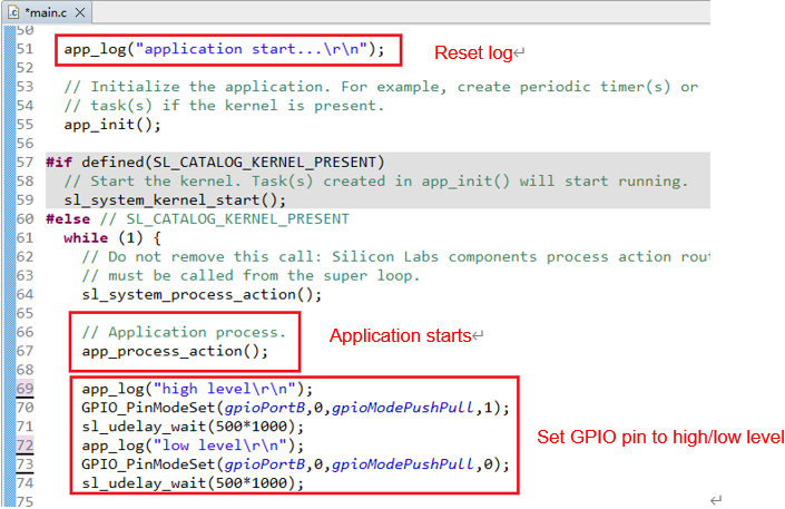
Program Description
Compile Application
The compilation steps for application examples of the HCM010S, HCM010S-E, HCM511S, and HCM511S-E modules are identical. This chapter uses the bt_soc_blinky_010s project as an example to demonstrate the compilation steps and compilation results.
Compilation Description
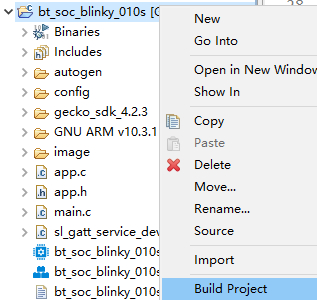
Select the target project on Simplicity Studio tool interface and then right-click the project. Click "Build Project" to compile the application.
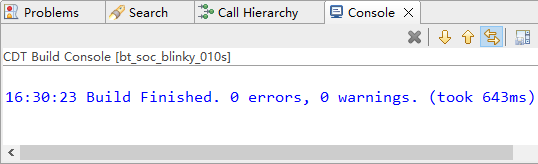
The interface of a successful compilation is as follows:
Compilation Result
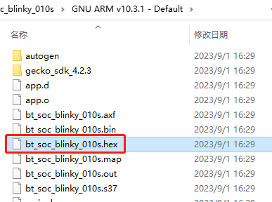
During compilation, the .hex file of the project is generated in the SimplicityStudio/v5_workspace/<project_name>/GNU ARM v10.3.1 -- Default directory (the project path set when the project is created).
Flash Firmware
This chapter explains how to download the firmware. Before firmware flashing, check whether the J-Link debugger is properly connected. If the J-Link debugger is properly connected, press the "Reset" button on the development board, and then start flashing the firmware.
When using HCM010S or HCM010S-E modules, before firmware flashing, configure the J-Link debugger as explained in *Steps 1* and *2* in *Chapter 3.1.1.1. When using HCM511S or HCM511S-E modules, before firmware flashing, configure the J-Link debugger as explained in Steps 1* and *2* in *Chapter 3.2.1.1*.
HCM010S/HCM010S-E Firmware Flashing
bt_soc_blinky_010s
According to the readme.md file of bt_soc_blinky_010s, before flashing the firmware (.hex file) of bt_soc_blinky_010s, you need a bootloader. Therefore, you should first flash the firmware generated after the compilation of bootloader project (bootloader-apploader_010s), and then flash the firmware of bt_soc_blinky_010s.
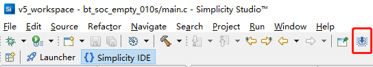
- Click the "Flash Programmer" icon on the Simplicity Studio tool interface to open the Flash Programmer tool.
Perform an erase operation before flashing the firmware (.hex file).
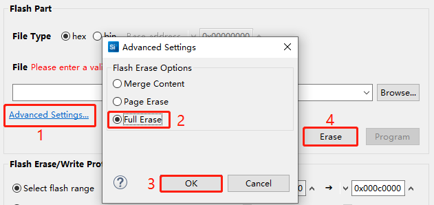
- Open the Flash Programmer tool and click "Advanced Settings..." on the tool interface. In the "Advanced Settings" window that pops up, select "Full Erase", click "OK", and then click "Erase" on the tool interface.
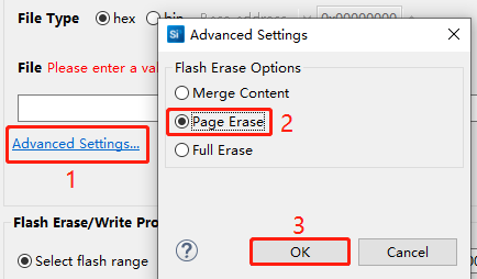
- Set the "Flash Erase Options" to "Page Erase" in the "Advanced Settings" interface, then click "OK".
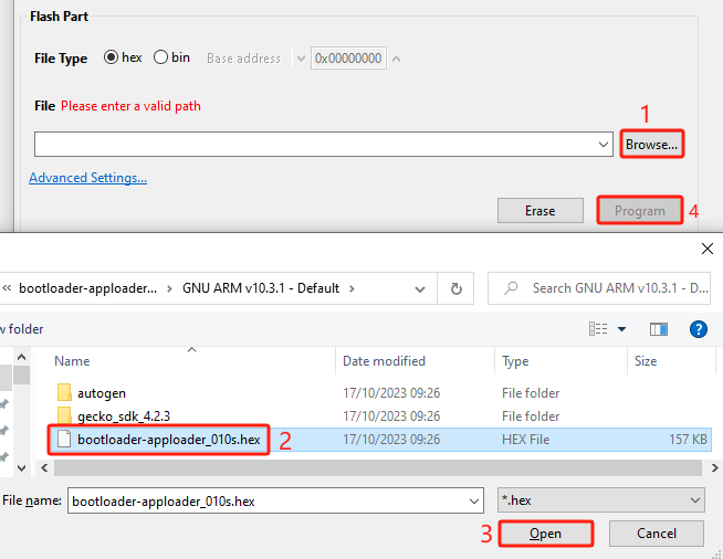
Click "Browse...", select the firmware (.hex file) of the bootloader project (bootloader- apploader_010s) on the "Select File" dialog that appears, and then click "[O]pen". Click "Program" to download the firmware of the bootloader project.
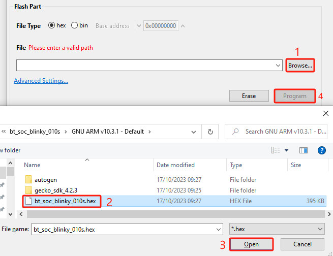
- Click "Browse..." and select the firmware (.hex file) of the bt_soc_blinky_010s project. Click "Program" to download the firmware of the bt_soc_blinky_010s project.
sleeptimer_baremetal_010s
- Open the Flash Programmer tool. See *Step 1* in *Chapter 5.1.1*.
- Perform an erase operation. See *Step 2* in *Chapter 5.1.1*.
- Flash the firmware of sleeptimer_baremetal_010s. See *Step 4* in *Chapter 5.1.1*.
bt_soc_empty_hcm010s_led
- Open the Flash Programmer tool. See *Step 1* in *Chapter 5.1.1*.
- Perform an erase operation. See *Step 2* in *Chapter 5.1.1*.
- Flash the firmware of bootloader-apploader_010s. See *Step 3* in *Chapter 5.1.1*.
- Flash the firmware of bt_soc_empty_hcm010s_led. See *Step 4* in *Chapter 5.1.1*.
HCM511S/HCM511S-E Firmware Flashing
bt_soc_blinky_511s
- Open Flash Programmer tool. See *Step 1* in *Chapter 5.1.1*.
- Perform an erase operation. See *Step 2* in *Chapter 5.1.1*.
- Flash the firmware of bootloader-apploader_511s. See *Step 3* in *Chapter 5.1.1*.
- Flash the firmware of bt_soc_blinky_511s. See *Step 4* in *Chapter 5.1.1*.
sleeptimer_baremetal_511s
- Open the Flash Programmer tool. See *Step 1* in *Chapter 5.1.1*.
- Perform an erase operation. See *Step 2* in *Chapter 5.1.1*.
- Flash the firmware of sleeptimer_baremetal_511s. See *Step 4* in *Chapter 5.1.1*.
bt_soc_empty_hcm511s_led
- Open the Flash Programmer tool. See *Step 1* in *Chapter 5.1.1*.
- Perform an erase operation. See *Step 2* in *Chapter 5.1.1*.
- Flash the firmware of bootloader-apploader_511s. See *Step 3* in *Chapter 5.1.1*.
- Flash the firmware of bt_soc_empty_hcm511s_led. See *Step 4* in *Chapter 5.1.1*.
Debug Program
This chapter describes the program debugging process.
Program Debugging for HCM010S/HCM010S-E
SoC Blinky
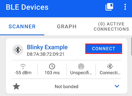
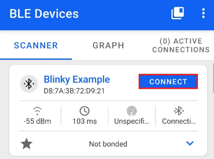
- Open the EFR Connect APP on your mobile phone and start scanning. Once the Blinky Example is scanned as shown in the figure below, click "CONNECT" to establish a connection.
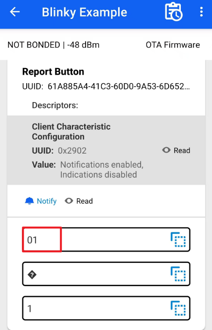
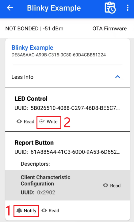
- After the connection is established, the following interface appears. Click "Notify" to enable notification functionality, then click "Write" to send data.

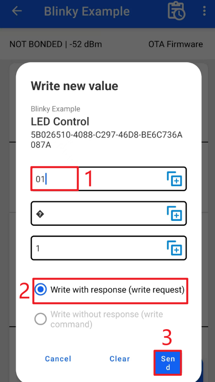
- Enter hex data 0x01 as shown in the following figure, select "Write with response (write request)", and then click "SEND" to send the data. The LED1 (PD02) on the development board is on.
The App receives notification data as shown in the figure below:
If 0x00 is sent, LED1 (PD02) is off.
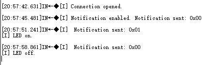
The following log is displayed in the debugging window of the serial port tool:
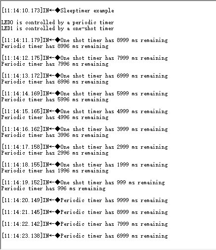
Sleeptimer Bare-metal
A total of three timers (one single-shot timer and two periodic timers) are set. After the development board is reset, the single-shot timer switches the state of LED1 (PD03) after 10 seconds. One periodic timer switches the LED0 (PD02) state (on/off) every 10 seconds, and the other periodic timer prints the remaining time of the above two timers every second. You can view the logs in the debugging window of the serial port tool. An example of the log is as follows:
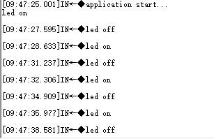
Soc Empty
After the development board is reset, the following log is displayed in the debugging window of the serial port tool. The 3 LED lights (PD02, PD03 and PD04) on the development board light up one by one and then turn off simultaneously. This process is repeated in a loop.
Program Debugging for HCM511S/HCM511S-E
SoC Blinky
- Open the EFR Connect APP on your mobile phone and start scanning. Once the Blinky Example is scanned as shown in the figure below, click "CONNECT" to establish a connection.
- After the connection is established, the following interface appears. Click "Notify" to enable notification functionality, then click "Write" to send data.
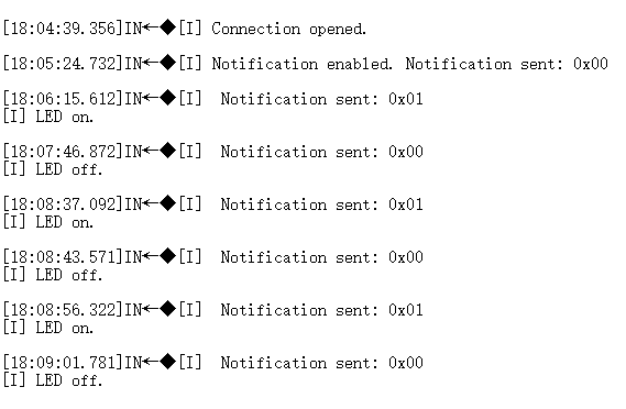
- Enter hex data 0x01 as shown in the following figure, select "Write with response (write request)", and then click "SEND" to send the data. The LED0 is on, that is, the PB00 on the development board is at a high level.

The App receives notification data as shown in the figure below:
If 0x00 is sent, LED0 is off, that is, the PB00 on the development board is at a low level.
The following log is displayed in the debugging window of the serial port tool:
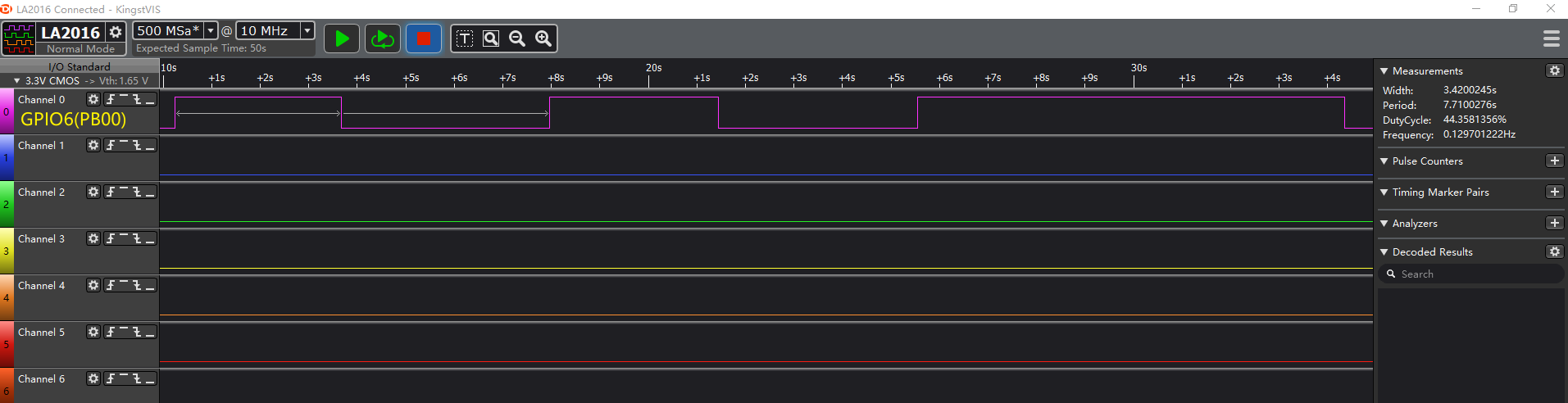
The voltage level changes corresponding to LED0 measured with a logic analyzer are as follows:
Sleeptimer Bare-metal
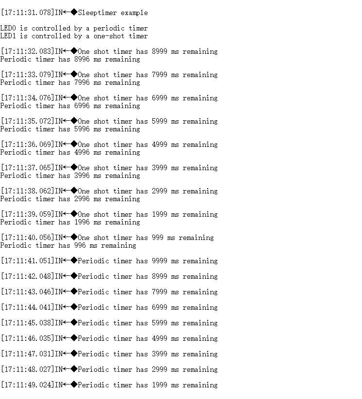
A total of three timers (one single-shot timer and two periodic timers) are set. After the development board is reset, the single-shot timer switches the state of LED1 after 10 seconds, that is, the voltage level of PB01 switches after 10 seconds. One periodic timer switches the LED0 state (on/off) every 10 seconds, that is, the voltage level of PB00 switches every 10 seconds. The other periodic timer prints the remaining time of the above two timers every second. You can view the logs in the debugging window of the serial port tool. An example of the log is as follows:
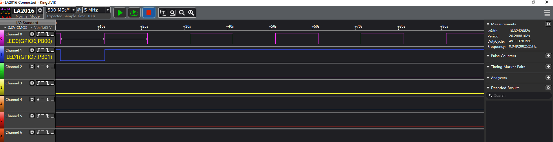
The voltage level changes corresponding to LED0 and LED1 measured with a logic analyzer are as follows:
Soc Empty
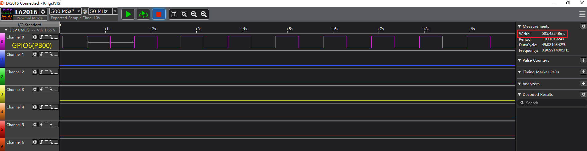
After the development board is reset, the following log is displayed in the debugging window of the serial port tool. LED0 is on for 0.5 seconds and then off for 0.5 seconds, that is, the PB00 on the development board is at a high level for 0.5 seconds, followed by a low level for 0.5 seconds. This process is repeated in a loop.
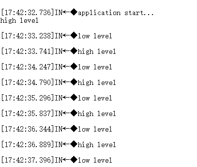
The voltage level changes corresponding to LED0 measured with a logic analyzer are as follows:
OTA and Quectel MAC Address
OTA
OTA Service
OTA service is added automatically when you create a Bluetooth project with Simplicity Studio. You can view the related OTA services in the config\btconf\gatt_configuration.btconf file.
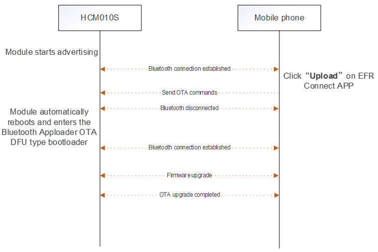
Enter Bluetooth Apploader OTA DFU type bootloader through OTA service to perform the OTA upgrade. For example, the upgrade progress for HCM010S module is as follows.
OTA Upgrade
This chapter uses the SoC Blinky project as an example to explain how to perform the OTA upgrade.
Download the firmware of the SoC Blinky project and the bootloader project (see *Chapter 5.1.1*).
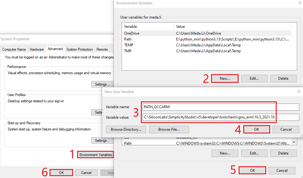
Right-click "This PC", click "Properties" > "Advanced system settings" > "Environment Variables" > "New", and then add the environment variables as shown in the figure below.
- Create a user variable PATH_GCCARM and set its value to the local path C:\SiliconLabs\SimplicityStudio\v5\developer\toolchains\gnu_arm\10.3_2021.10.
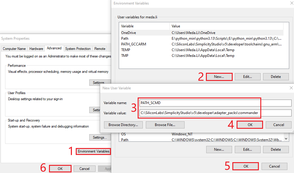
- Create a user variable PATH_SCMD and set its value to the local path C:\SiliconLabs\SimplicityStudio\v5\developer\adapter_packs\commander.
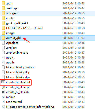
- Double-click the create_bl_files.bat file in the SoC Blinky project, and then the output_gbl folder is generated automatically.
- Copy the application.gbl file from the output_gbl folder to the target folder of your mobile phone (the storage location is user-defined).
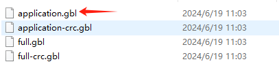
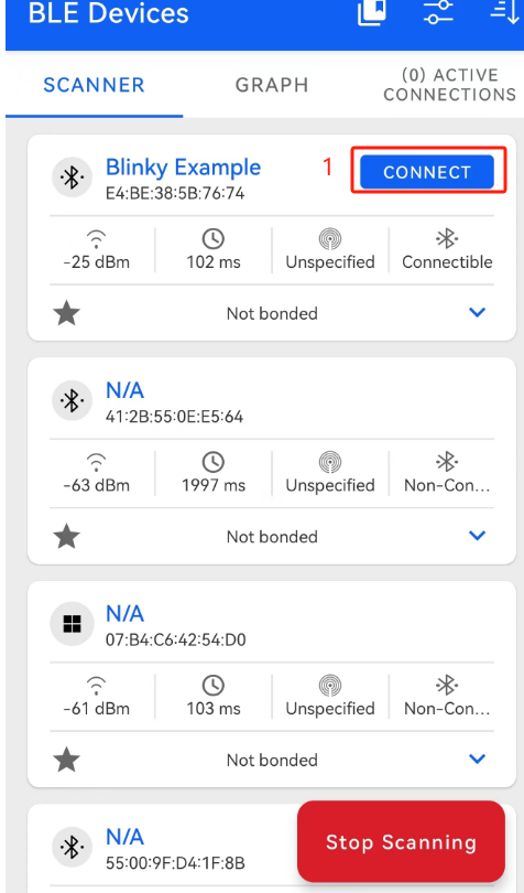
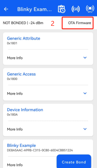
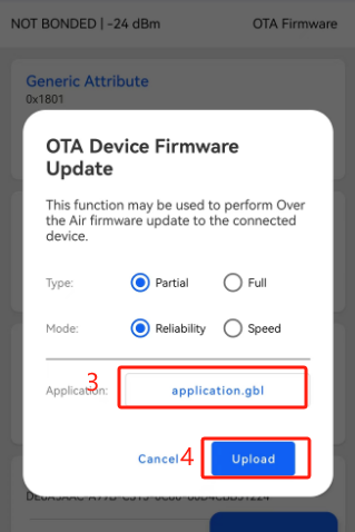
- Open the EFR Connect APP on your mobile phone and start scanning. Once the Blinky Example appears, click "CONNECT" to establish a connection. Then click "OTA Firmware" to perform the OTA upgrade. When the "OTA Device Firmware Update" interface is displayed, select "application.gbl" in "Application" text box and click "Upload".

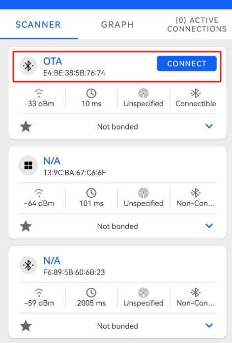
- If the upgrade fails, you can select the "OTA" device in the scan interface, and then click "CONNECT" to retry the upgrade.
Quectel MAC Address
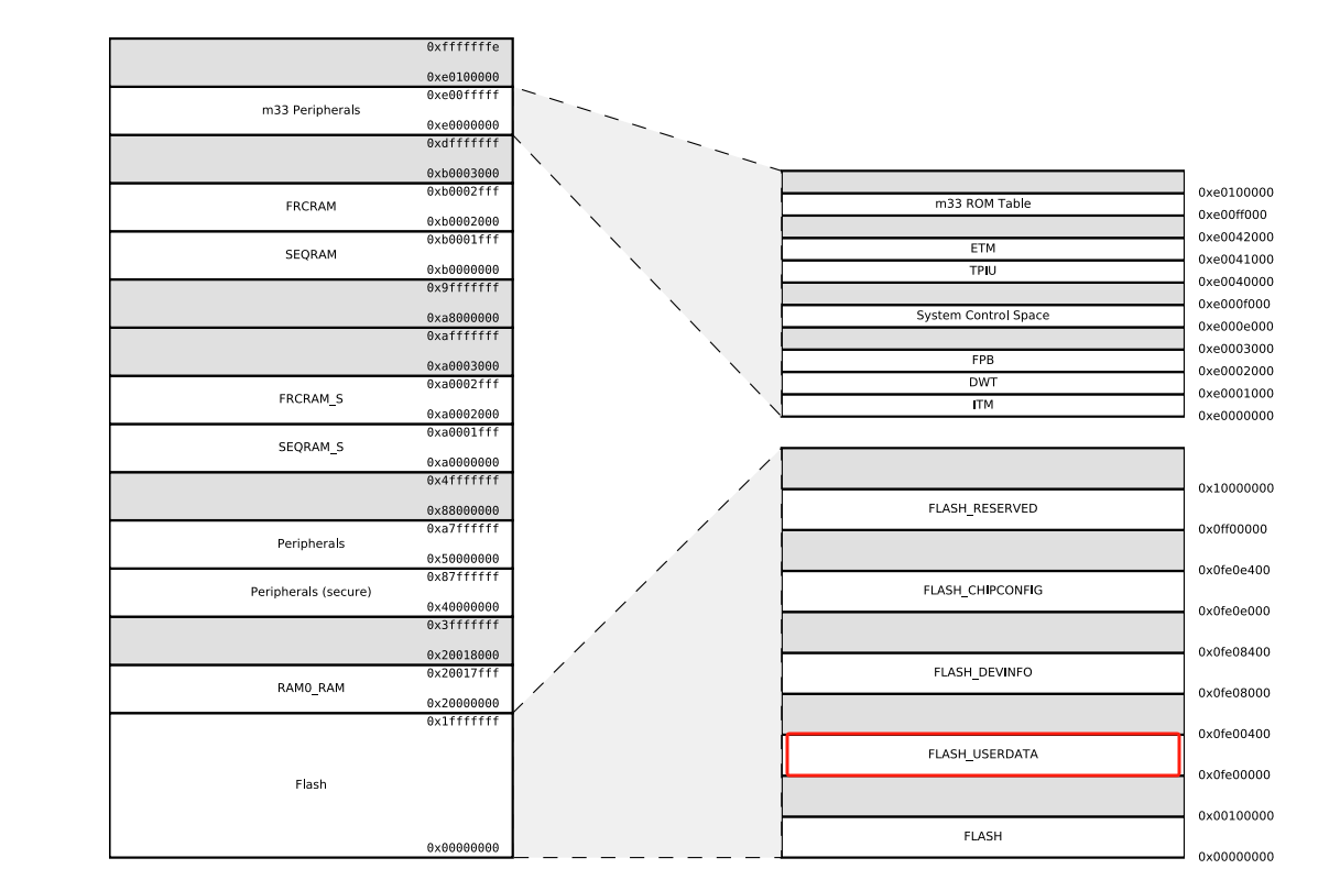
MAC address of the chip manufacturer is used by default. Alternatively, you can use the MAC address assigned by Quectel. The Quectel MAC address information is stored in the FLASH_USERDATA area of the built-in flash memory of the chip.
Execute the following steps to use the Quectel MAC address.
- Add the following code to the app.c file of the project you have created.
typedef struct tag_quec_mac_info{
  uint8_t mac_flag[2];
  bd_addr mac;
}QUEC_MAC_INFO_T;

void flash_param_read(uint8_t *buffer , uint32_t len)
{
  memcpy(buffer,(void *)(USERDATA_BASE) , len);
}

int quec_get_mac(bd_addr *addr)
{
    QUEC_MAC_INFO_T _mac_info;
    flash_param_read((uint8_t *)&_mac_info,sizeof(QUEC_MAC_INFO_T));

    if(_mac_info.mac_flag[0] != 0xAA || _mac_info.mac_flag[1] != 0xAA)
      return -1;

    addr->addr[0] = _mac_info.mac.addr[5];
    addr->addr[1] = _mac_info.mac.addr[4];
    addr->addr[2] = _mac_info.mac.addr[3];
    addr->addr[3] = _mac_info.mac.addr[2];
    addr->addr[4] = _mac_info.mac.addr[1];
    addr->addr[5] = _mac_info.mac.addr[0];

    return 0;
}
- Add the following code to the sl_bt_evt_system_boot_id event in sl_bt_on_event() in the app.c file.
case sl_bt_evt_system_boot_id:
{
      ......
      uint8_t type = 0;
      bd_addr get_addr;
      if(!quec_get_mac(&get_addr))
      {
          // Using Quectel MAC address
          sl_bt_system_set_identity_address(get_addr,0);//0 mean public address
      }
      else
      {
          // Using Default Silicon labs Mac address
          sl_bt_system_get_identity_address(&get_addr,&type);
      }
      sl_bt_system_get_identity_address(&get_addr,&type);
      ......
}break;
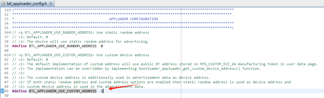
Change the value of the BTL_APPLOADER_USE_CUSTOM_ADDRESS macro from 0 to 1 in the ./config/btl_apploader_config.h file of the bootloader project.
Make sure that the
bootloader_apploader_get_custom_device_address()in the ./gecko_sdk_4.2.3/platform/bootloader/communication/apploader/btl_apploader_common.c file of the bootloader project is as follows:
#define MFG_CUSTOM_EUI_64_OFFSET 0x0000
SL_WEAK void bootloader_apploader_get_custom_device_address(sl_apploader_address_t *btAddress)
{
  uint8_t *mfgToken = (uint8_t*)USERDATA_BASE + MFG_CUSTOM_EUI_64_OFFSET;
  uint8_t mfgAddressType = 0;
  uint8_t *mac_flag = &mfgToken[0];
  uint8_t *mfgAddress = &mfgToken[2];
  uint8_t mfgAddressLen = sizeof(btAddress->address);

  if(mac_flag[0] == 0xAA && mac_flag[1] == 0xAA)
  {
      //Adjust token byte Endianness
      for (uint8_t i = 0; i < mfgAddressLen; i++) {
        btAddress->address[i] = mfgAddress[(mfgAddressLen - 1) - i];
      }
  }

  if (mfgAddressType == 0) {
    btAddress->type = sl_apploader_address_type_public;
  } else if (mfgAddressType == 1) {
    btAddress->type = sl_apploader_address_type_random;
  } else {
    // if invalid address type assume public
    btAddress->type = sl_apploader_address_type_public;
  }
}
Appendix References
Related Documents
| Document Names |
|---|
| 1. Quectel_HCM010S-TE-B_User_Guide |
| 2. Quectel_HCM511S-TE-B_User_Guide |
| 3. Quectel_HCM010S-E-TE-B_User_Guide |
| 4. Quectel_HCM511S-E-TE-B_User_Guide |
| 5. Quectel_HCM010S_Hardware_Design |
| 6. Quectel_HCM010S-E_Hardware_Design |
| 7. Quectel_HCM511S_Hardware_Design |
| 8. Quectel_HCM511S-E_Hardware_Design |
Terms and Abbreviations
| Abbreviation | Description |
|---|---|
| APP | Application |
| DFU | Device Firmware Update |
| GATT | Generic Attribute Profile |
| GND | Ground |
| GPIO | General-Purpose Input/Output |
| IO | Input/Output |
| IDE | Integrated Development Environment |
| LED | Light Emitting Diode |
| MAC | Medium Access Control |
| OTA | Over-the-air programming |
| PC | Personal Computer |
| SDK | Software Development Kit |
| USART | Universal Synchronous/Asynchronous Receiver/Transmitter |
| USB | Universal Serial Bus |